3D Printed Rotary Clock
by MatiasMamo in Workshop > 3D Printing
7034 Views, 196 Favorites, 0 Comments
3D Printed Rotary Clock

Hi, everybody!
I decided to make this clock as a challenge to myself. I am not either a designer or an engineer, so it was really challenging for me! All the pieces were designed with 123D Design, very simple yet powerful tool.
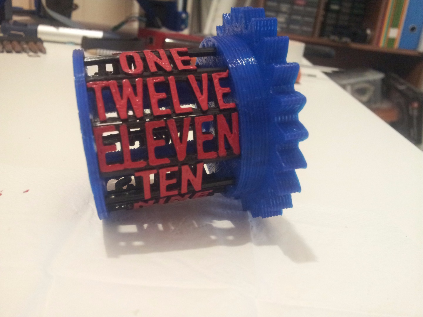
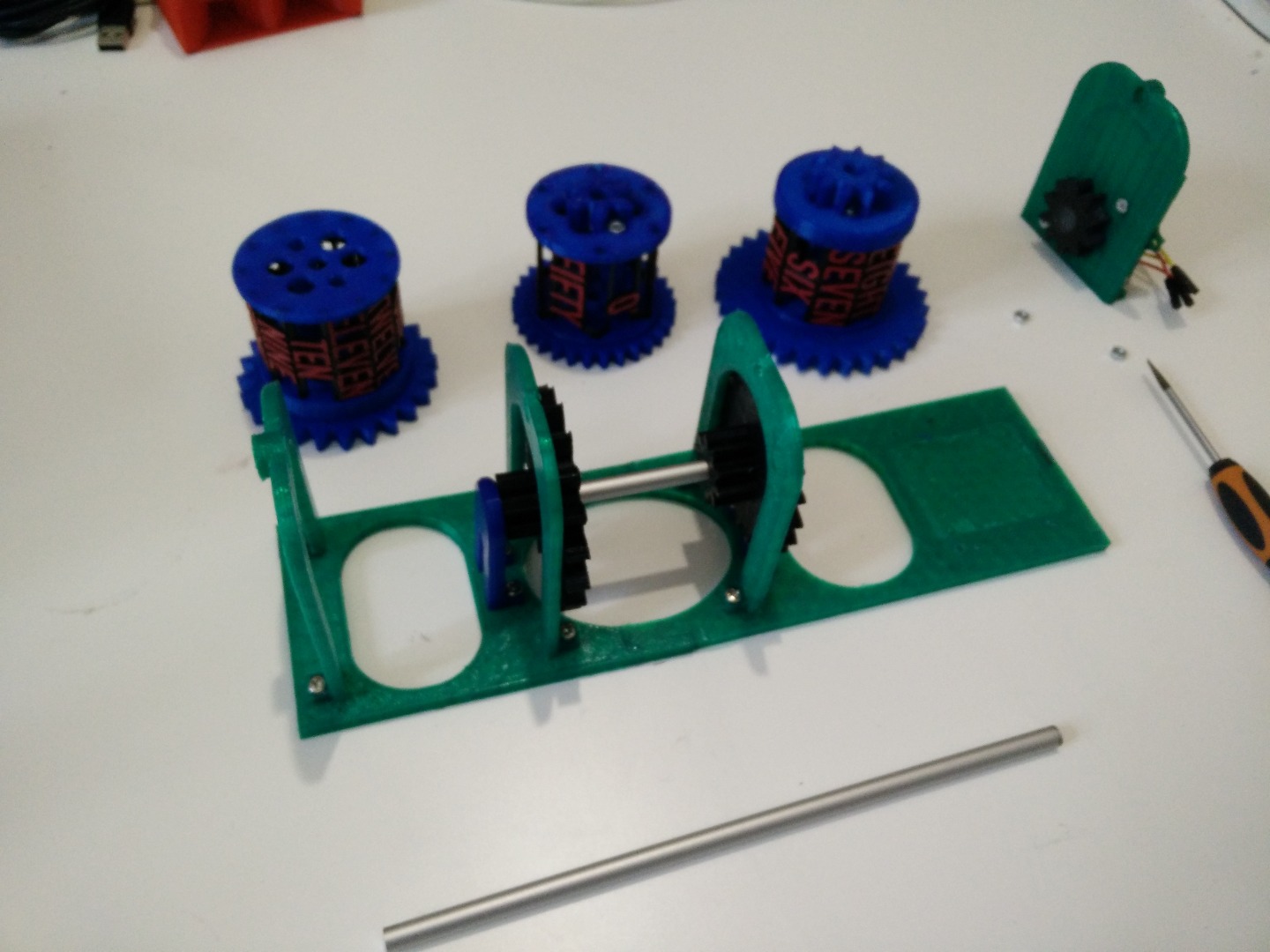
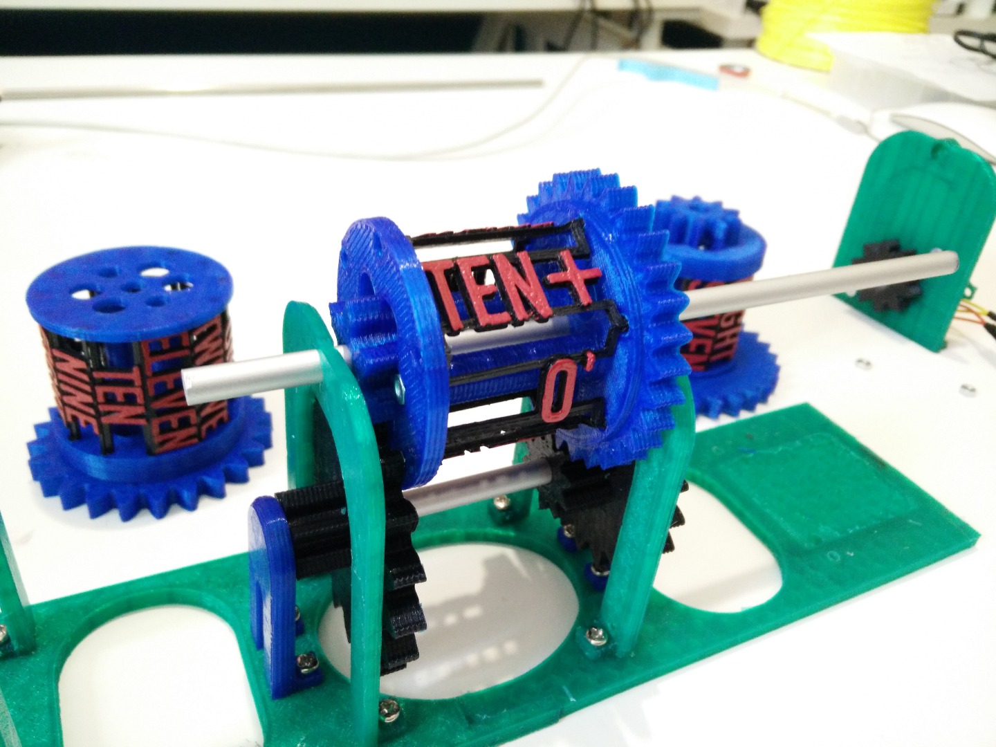
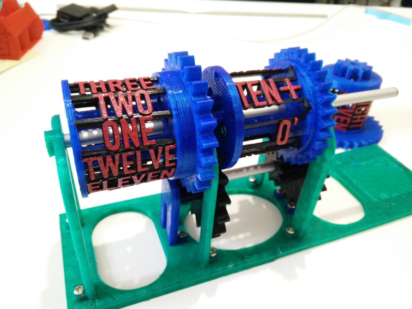
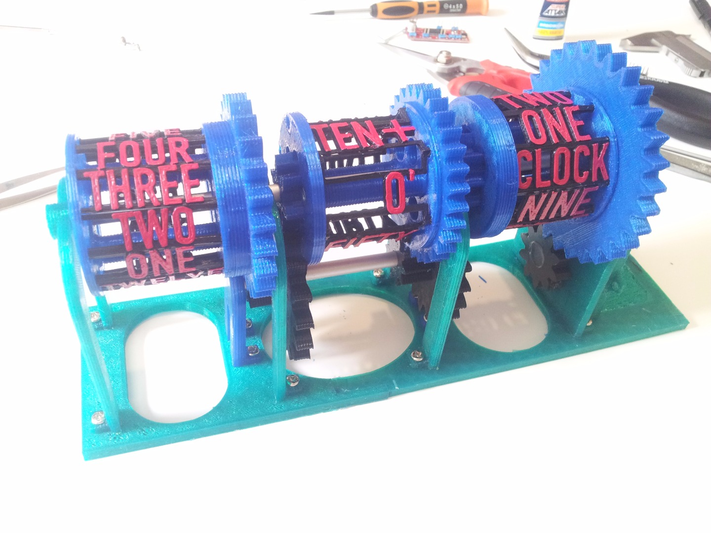
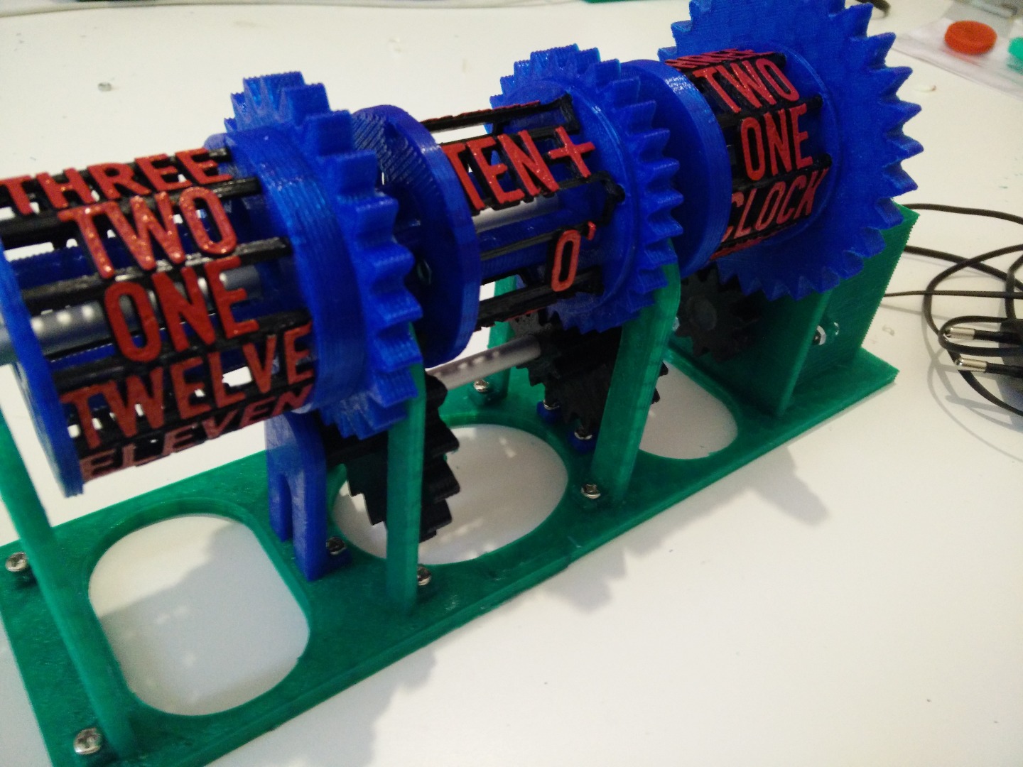
As you can see, the clock has three rotors: the left one shows the hour, the middle and the right one show the minutes. The entire mechanism is powered by one single stepper motor, hidden inside the little box on the left.
Let's start!
Tools and Materials
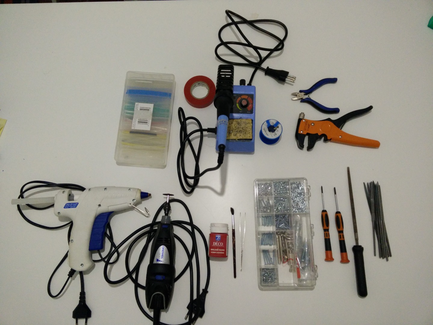
The tools you will need to make this instructable are:
- 3D printer (very important)
- something to cut metal, like a rotary tool (you only use this a couple of times)
- screwdrivers
- a computer
- soldering iron
Plus this parts:
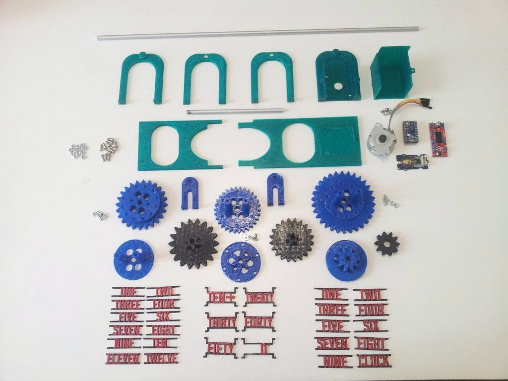
- all the 3D printed parts
- a not-so-big stepper motor
- Arduino mini (or nano, or similar)
- one EasyDriver (or some stepper motor driver)
- an RTC (like the DS1307) if you want precision over long periods of time
- (at least) 280x6mm aluminum tube (7 inches, 6mm diameter)
- 14 M3x8mm screws
- 8 M3x10mm screws
- 22 bolts (this should be obvious, anyway...)
- TONS of patience
Optional
- some acrylic paint (+ brush, ecc...)
Printing
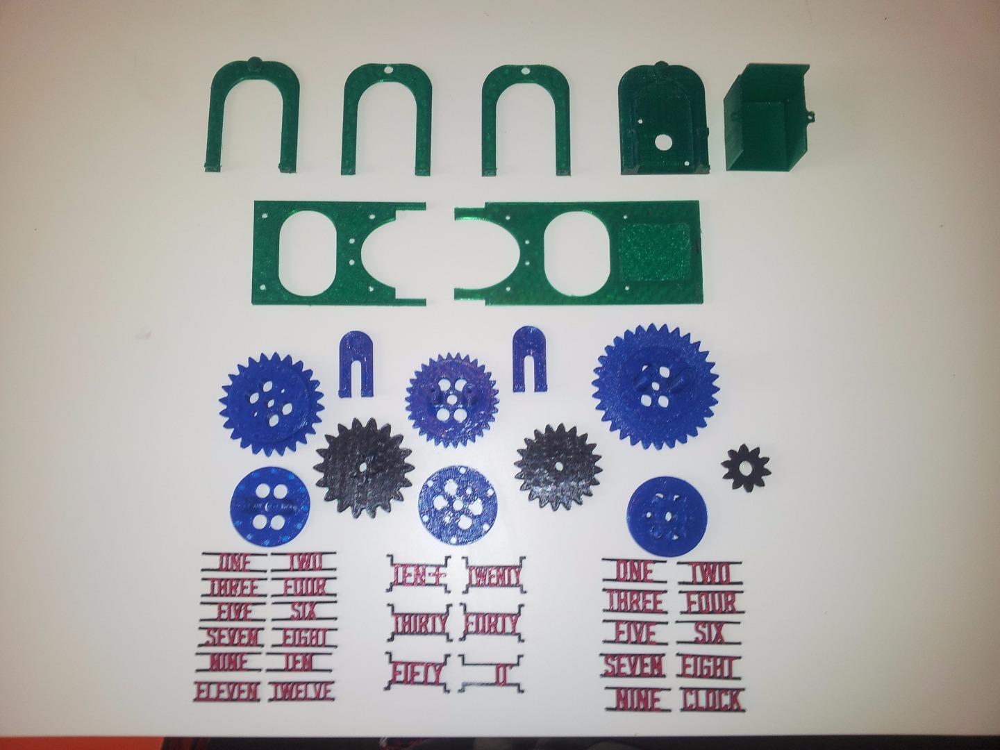
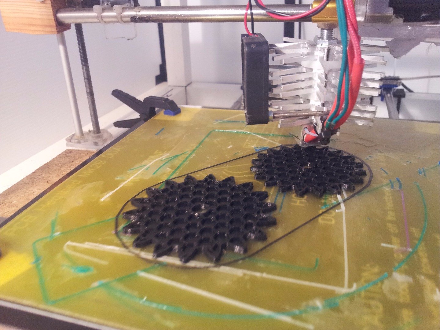
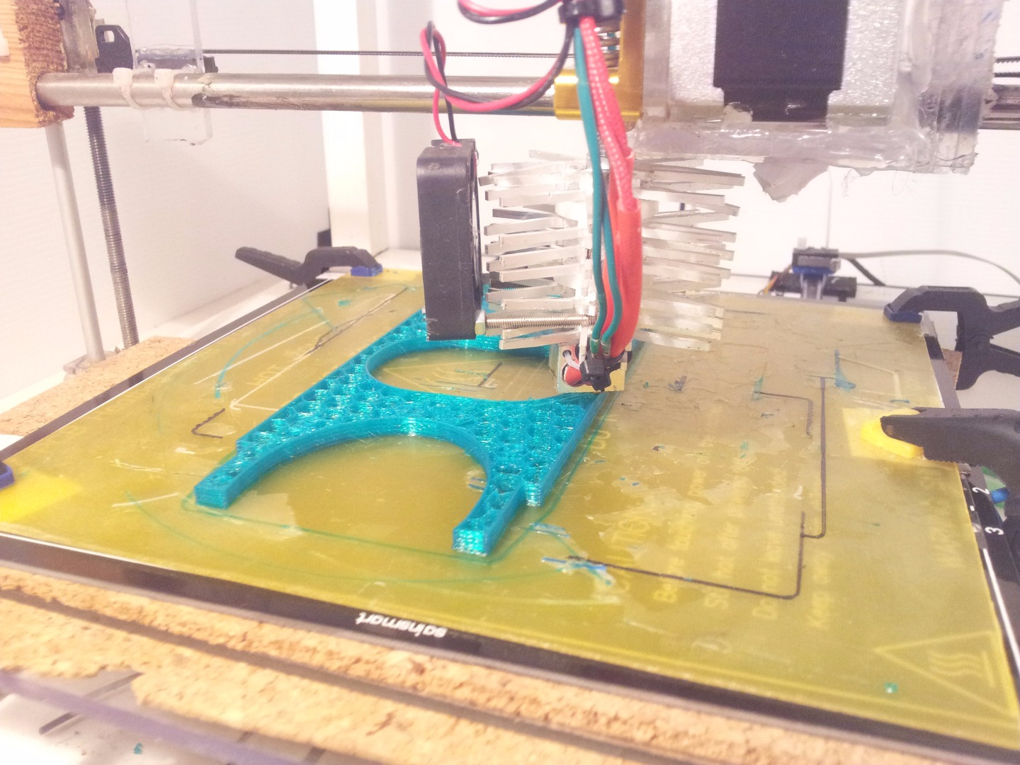
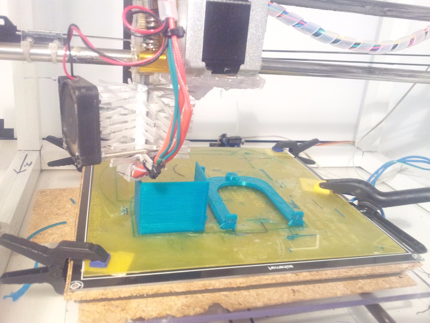
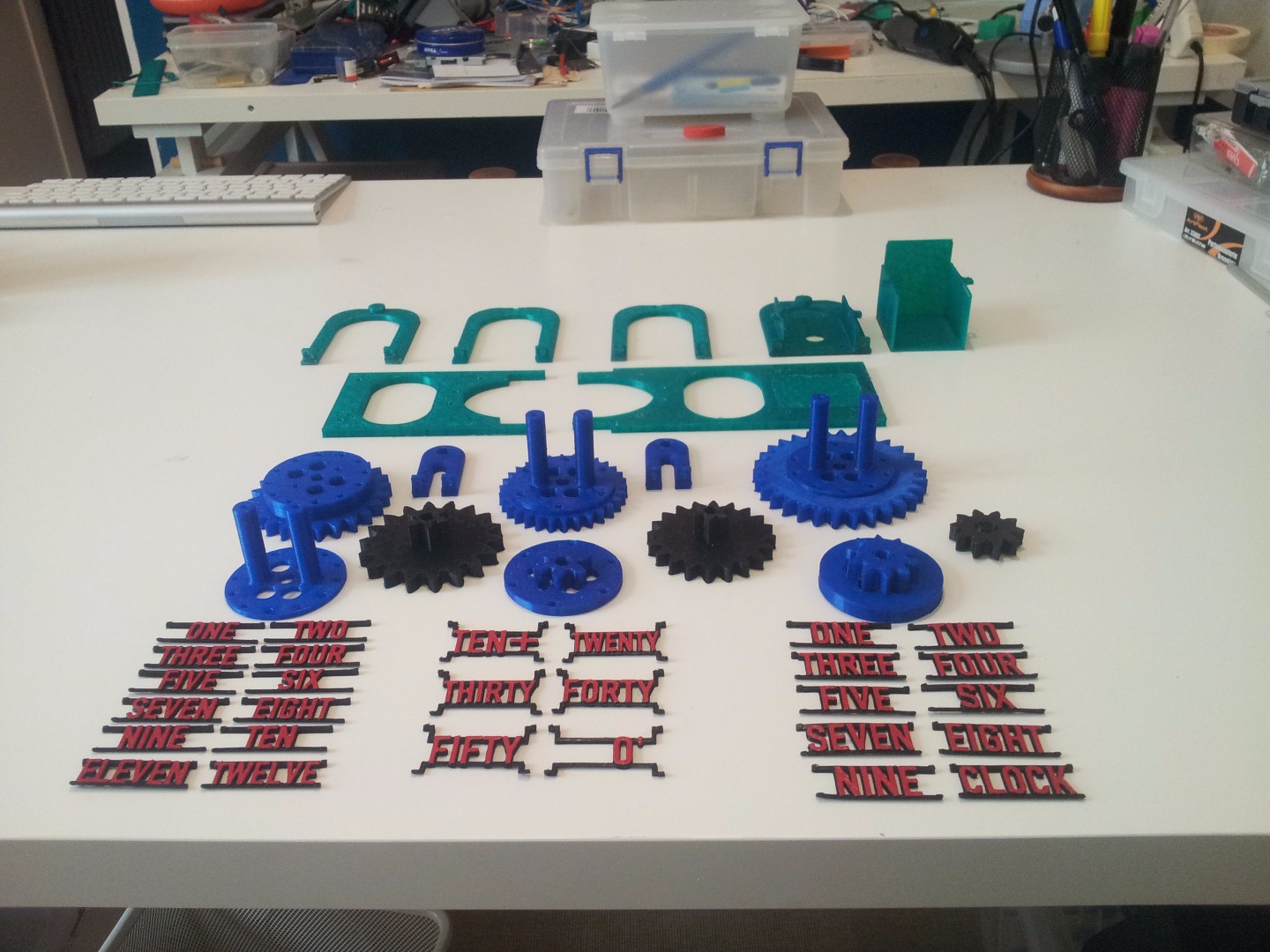
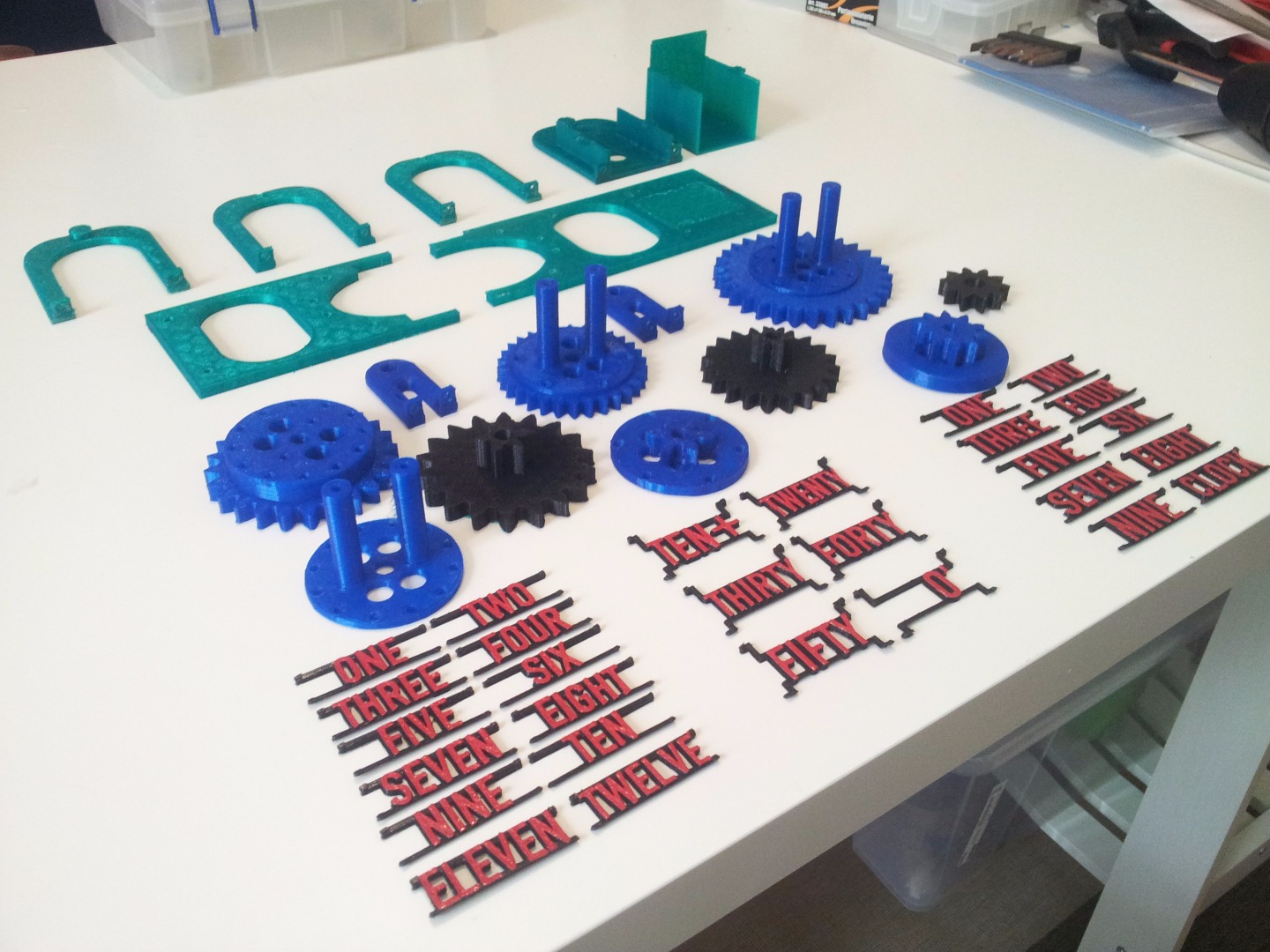
This is the simplest to describe yet the most time consuming step: Print everything. You can find all the .stl files at the end of this step.
Before starting, you should think about the colors of the various parts. All my printed parts are made in PLA and weight ~230g.
My printing settings (for all the parts):
- no support, no raft layers
- 2 solid layer bottom, 4 on top
- 2 perimeters
- 10% to 15% infill
- 0.2mm layer height
Downloads
Little Corrections
Depending on the precision of your printer, some of the parts might have little imperfections. Most of them are not important, but some can cause problems.
- The diameter of the axis holes has to be correct. This means that if you use a 6mm bar (as you should) the holes have to be a bit bigger. Test if the rotors rotate smoothly and, if they don't, enlarge the holes with something like a file or a 6.5mm drill bit.
- The labels' pins might need a little correction.
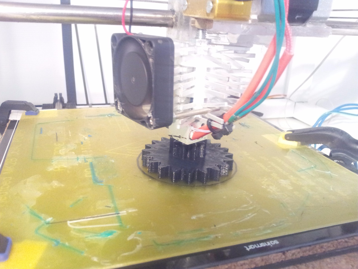
- The first layer of the gears may create some problems. If the nozzle is too near to the plate while printing the first layer (or if it's releasing too much material) the first layer may result bigger than the rest of the gear. Simply file it a little.
Considerations on Some Parts
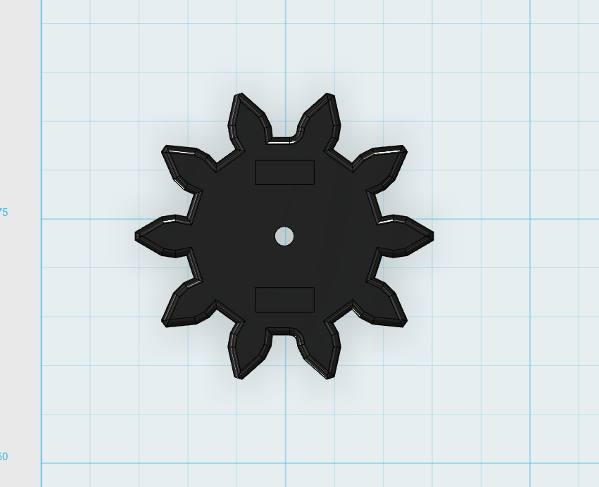
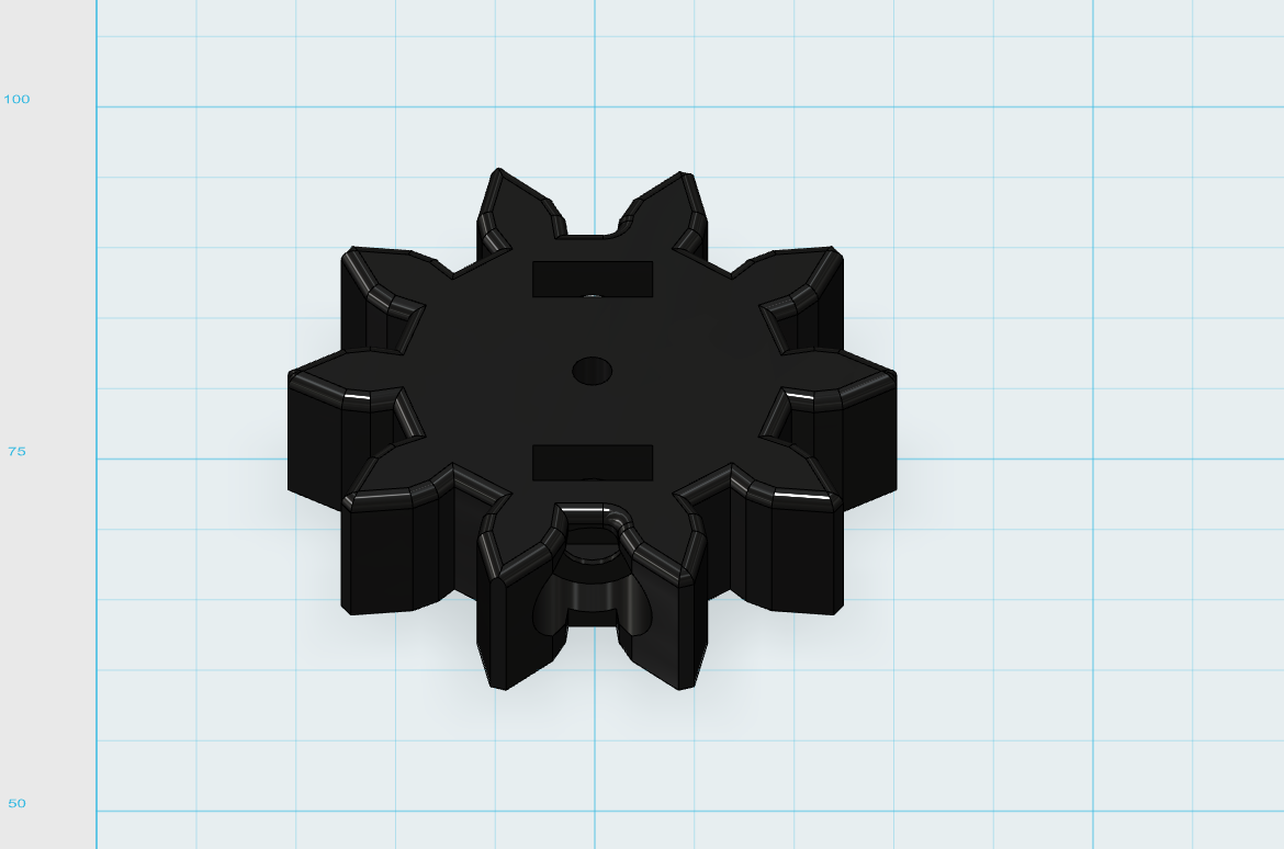
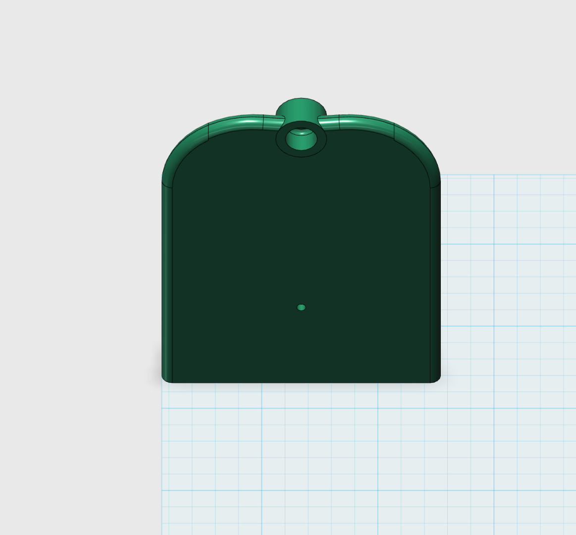
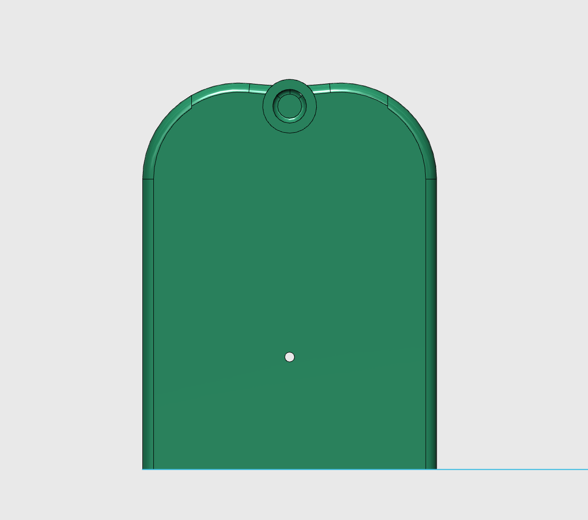
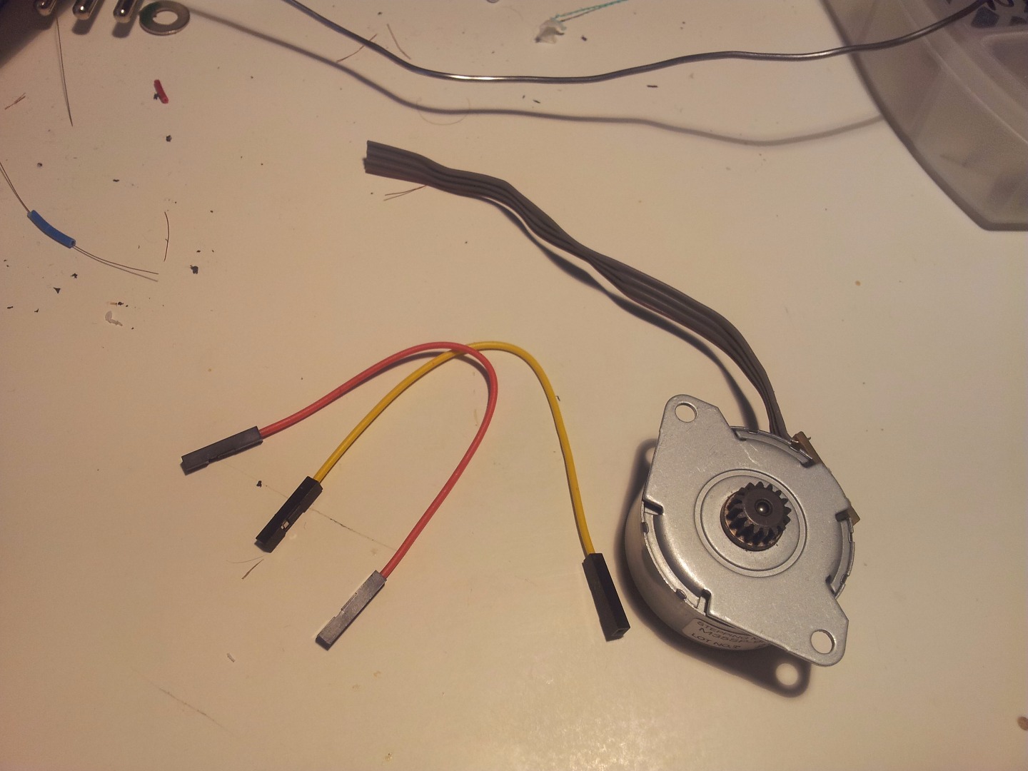
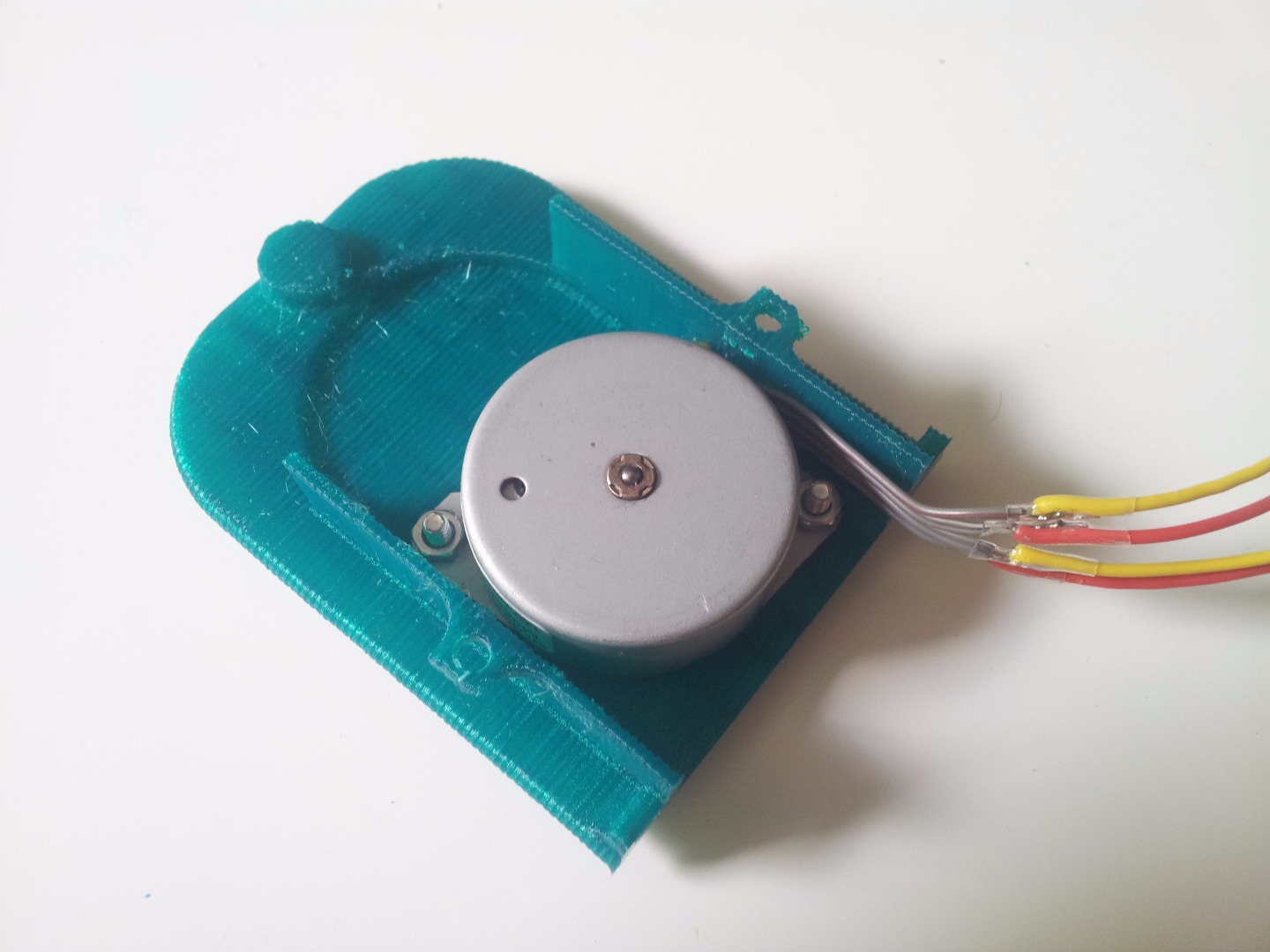
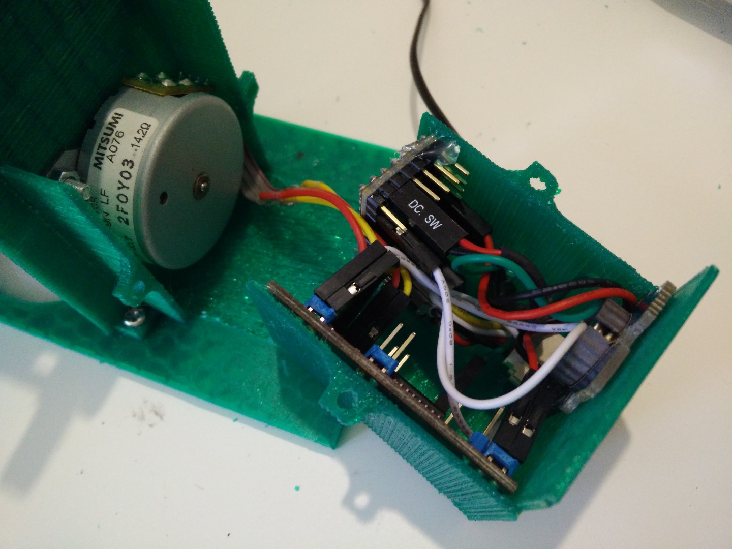
I think you might encounter some problems on the parts "around" the motor. I mean, is very improbable that you have a motor exactly like mine! (I took it from an old scanner)
So I decided to add two more models (which you find in the folder blanks) of the gear directly attached to the motor and the support on which you screw the motor. These two models are without the holes (for shaft and screws) so you can adapt it to your motor.
They both have a 2mm hole on the rotation axis, so you can easily find where to drill.
I hope this can be useful for some of you!
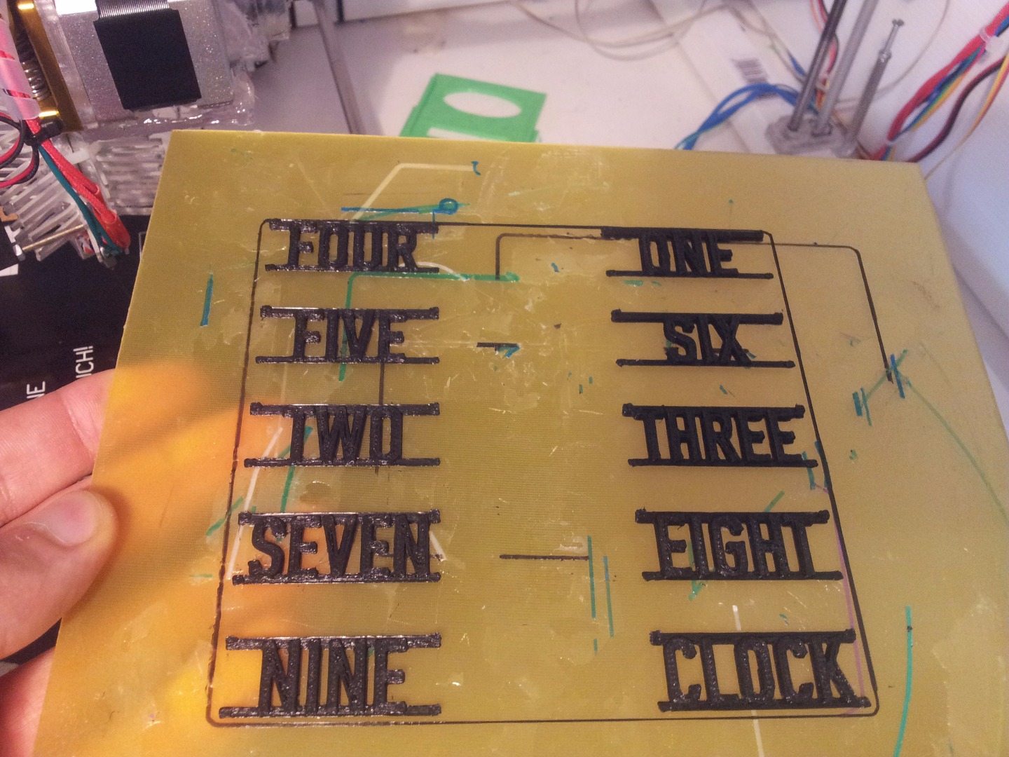
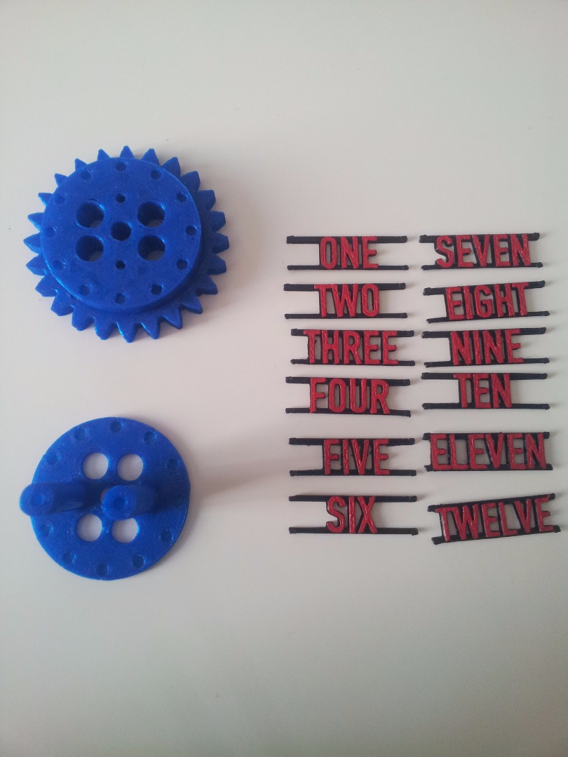
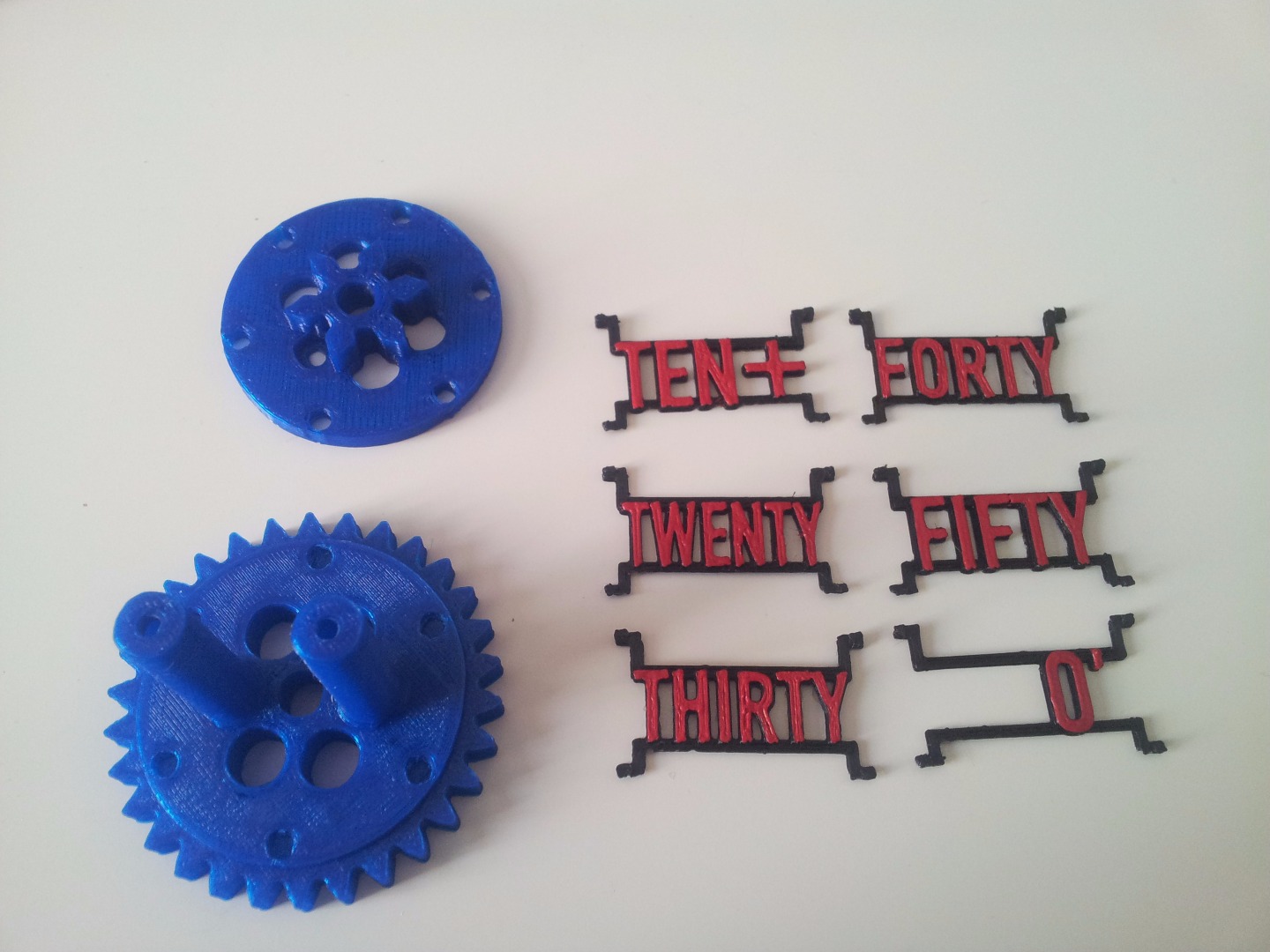
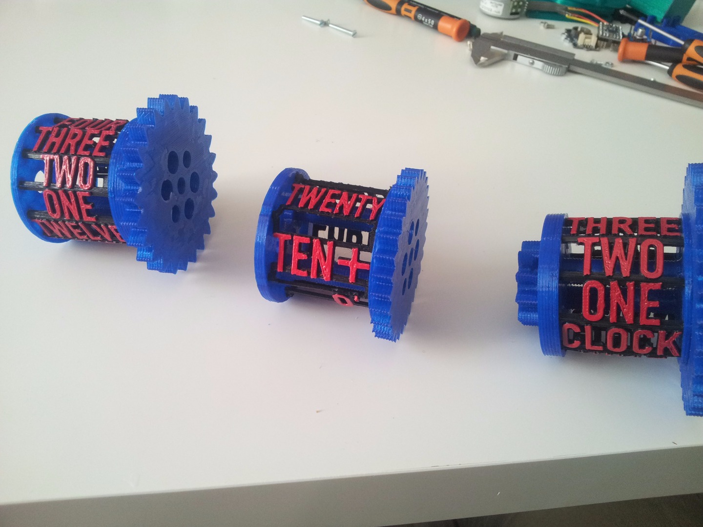
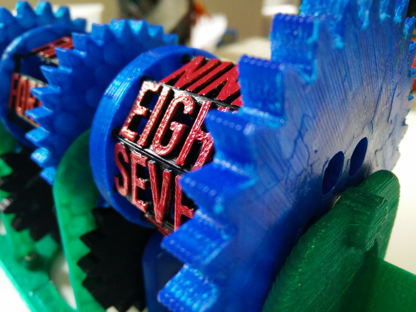
Painting the Labels
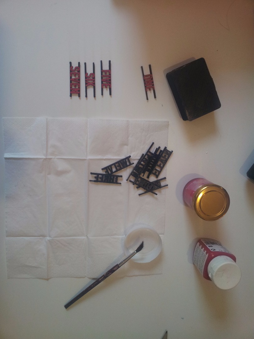
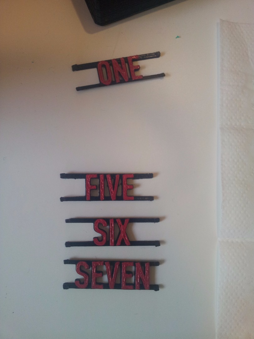
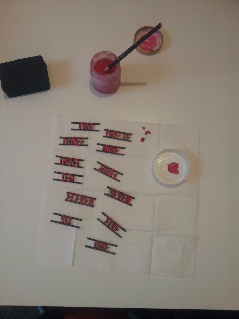
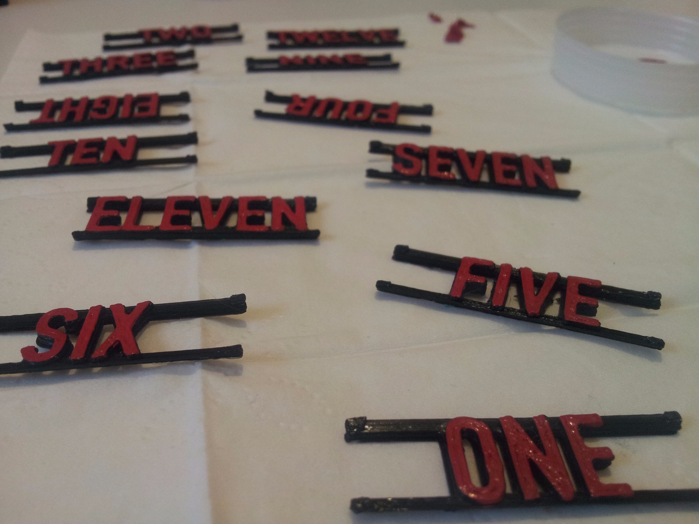
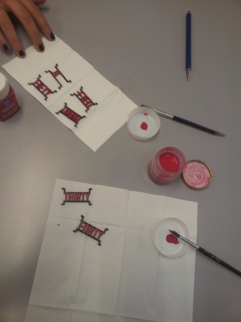
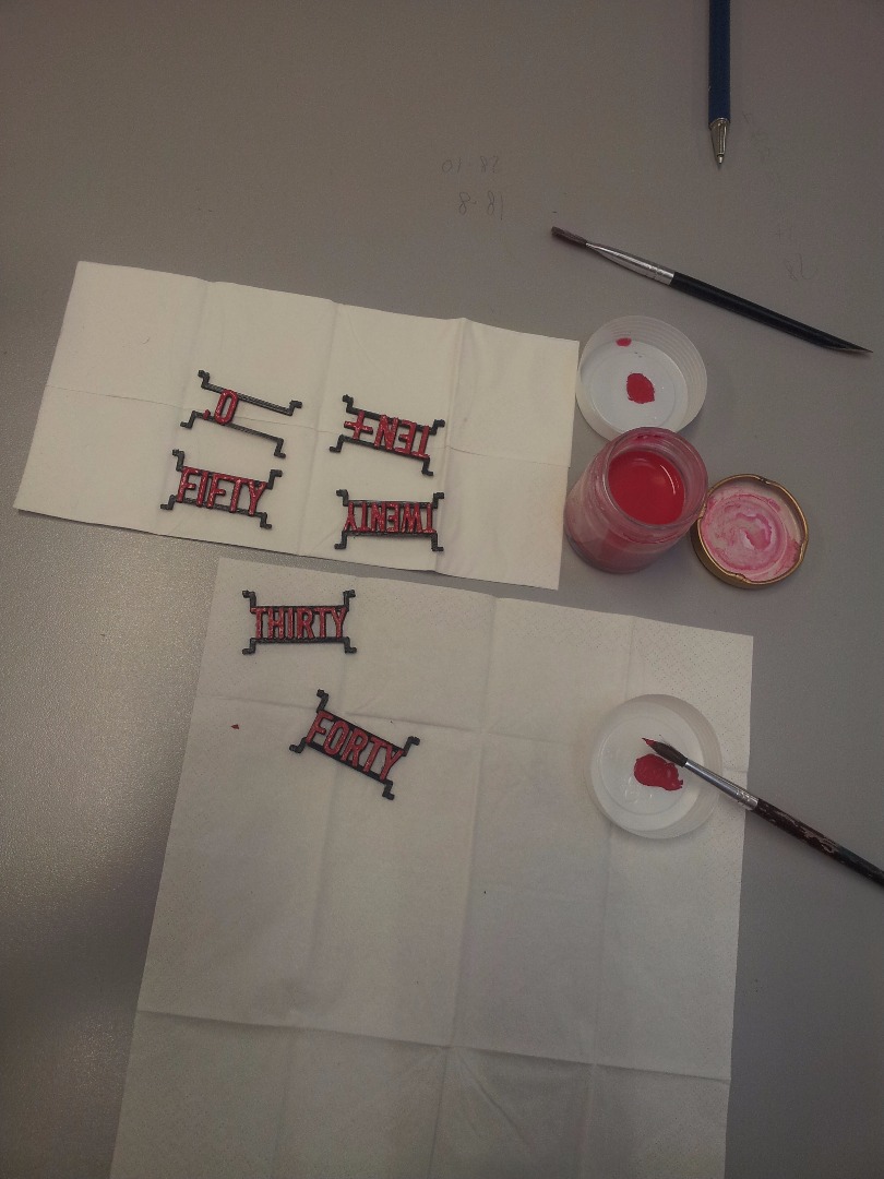
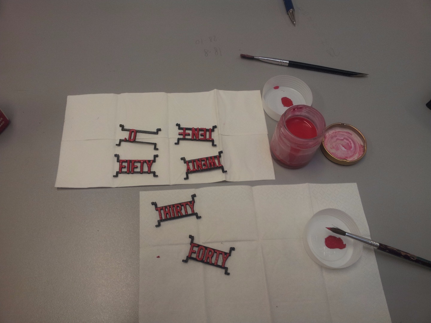
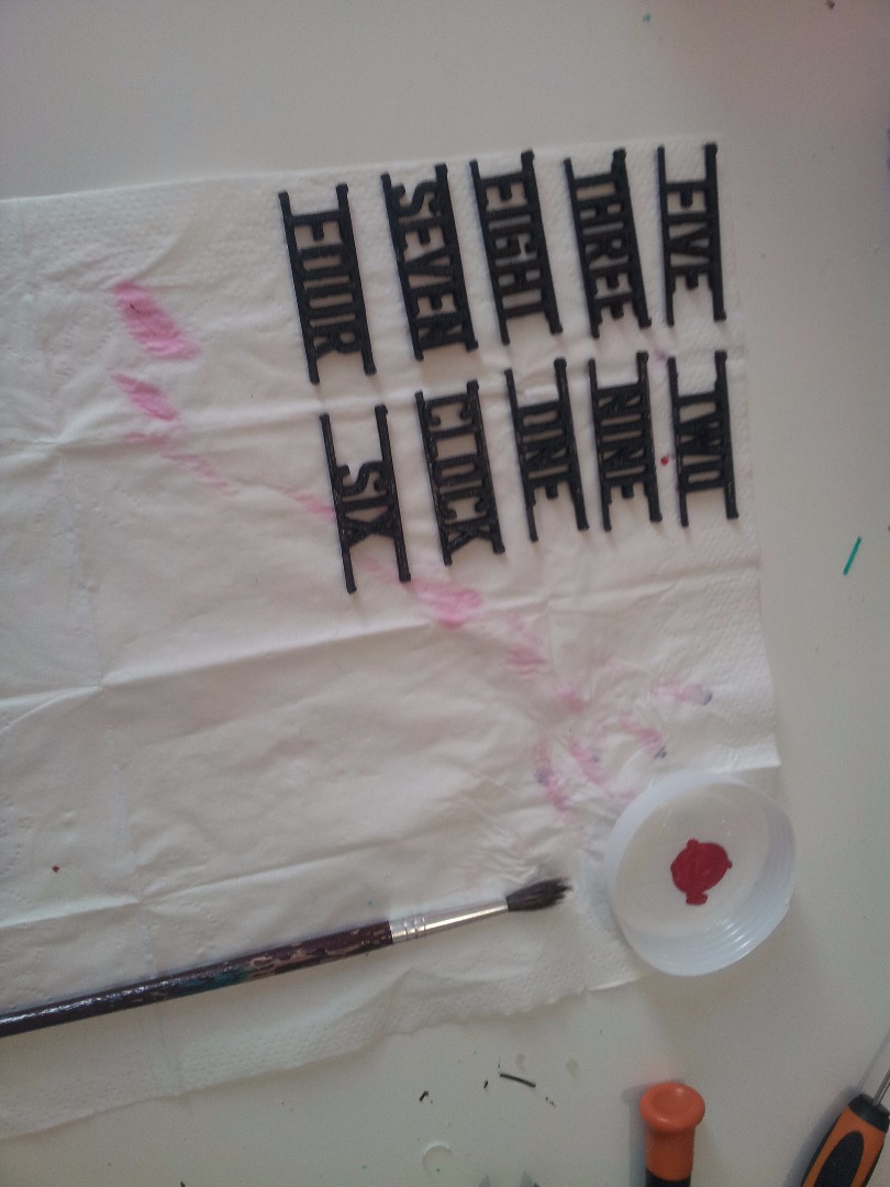
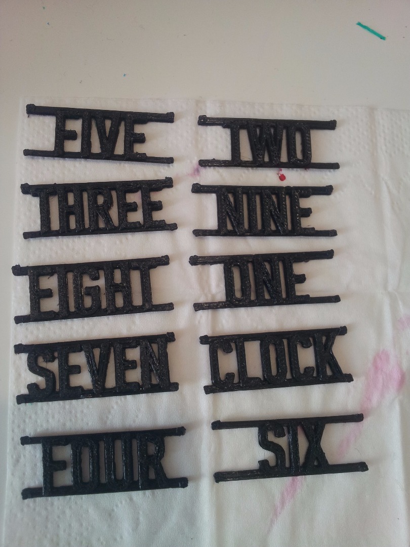
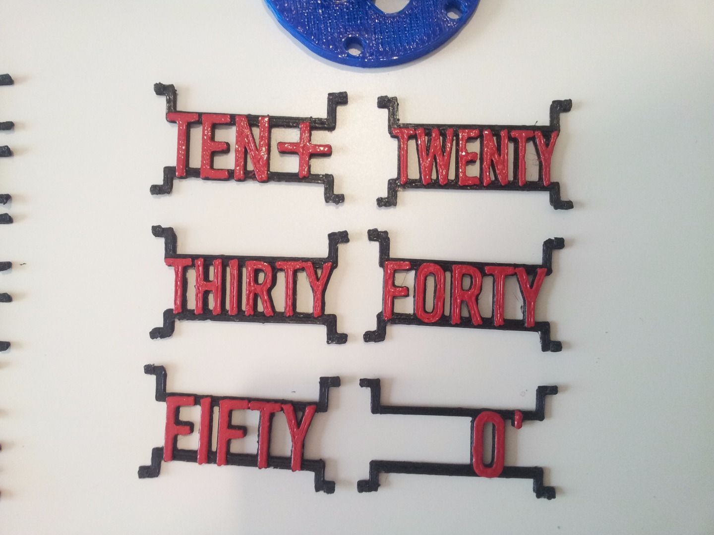
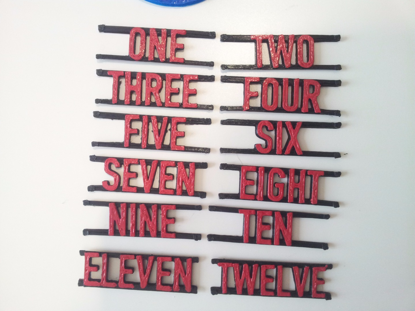
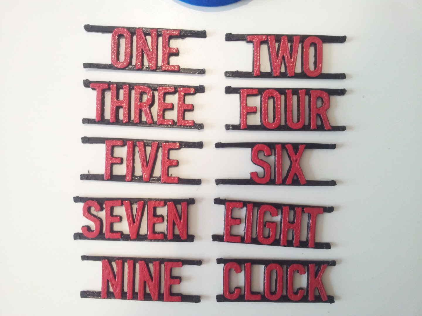
Since I have not a dual extruder printer, I decided to print all the labels in black and then paint them. I think it was the best choice since the result looks good.
As said in the "Tools and materials" step, you will need some acrylic paint in order to paint on plastic (it works both for ABS and PLA). You should choose a color that highlights the words. It could be a good idea to print the labels with glow-in-the-dark plastic.
I simply applied two or three layers of color on every label. The color dries pretty fast (only 10-15 minutes), so you can paint all the labels in a couple of hours.
Cutting Screws and Bars
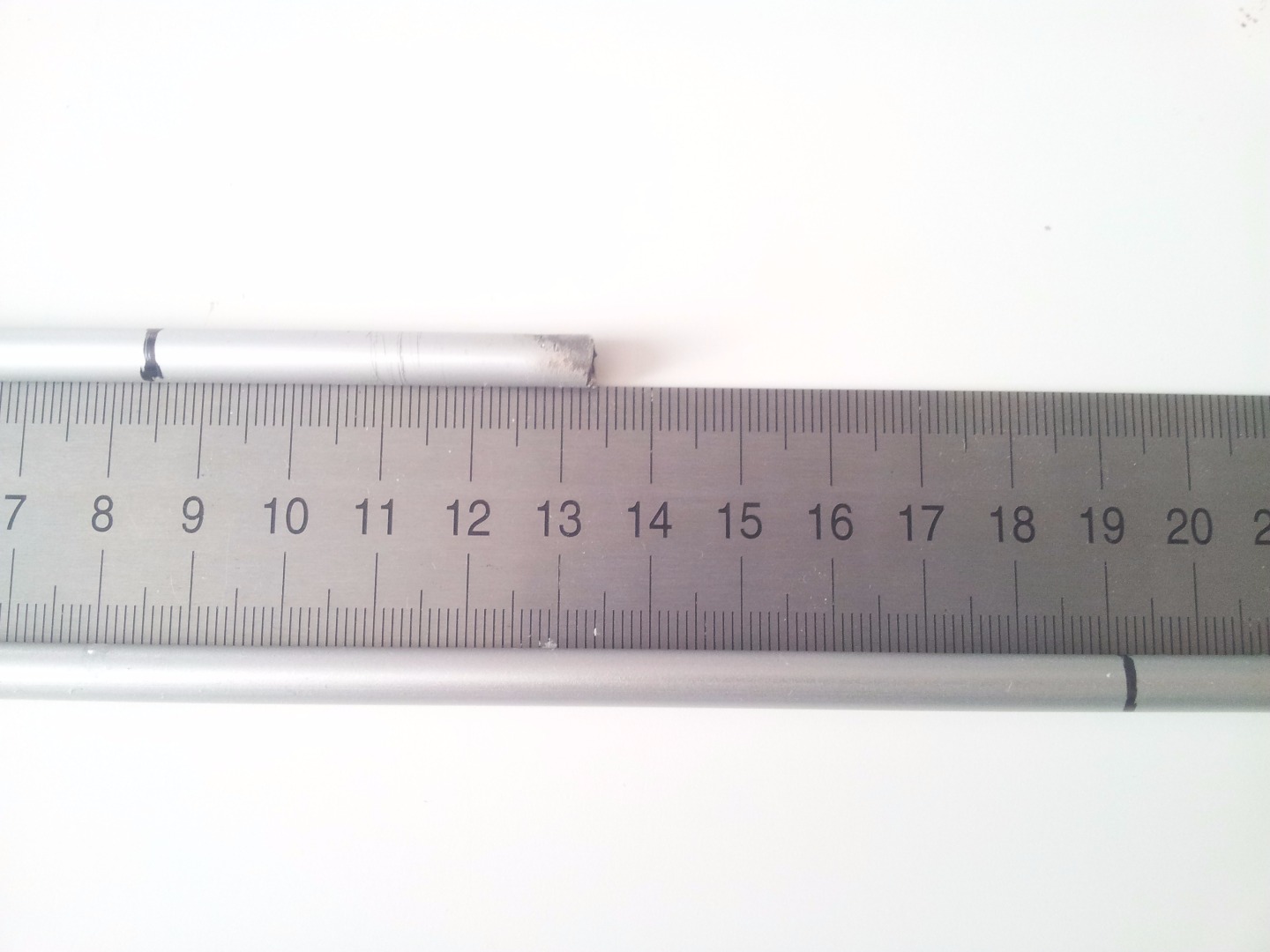

You need to cut:
- Two screws to 6mm (head excluded)
- Two screws to 4mm (head excluded)
- Two aluminum (it can also be steel or whatever) bars to 190mm and 85mm (6mm diameter)
The two longer screw will be used for mounting the middle rotor; the two shorter ones for attaching the gear directly to the motor.
The bars will be used as axises: the longer one for the rotors and the shorter one for the transmission gears.
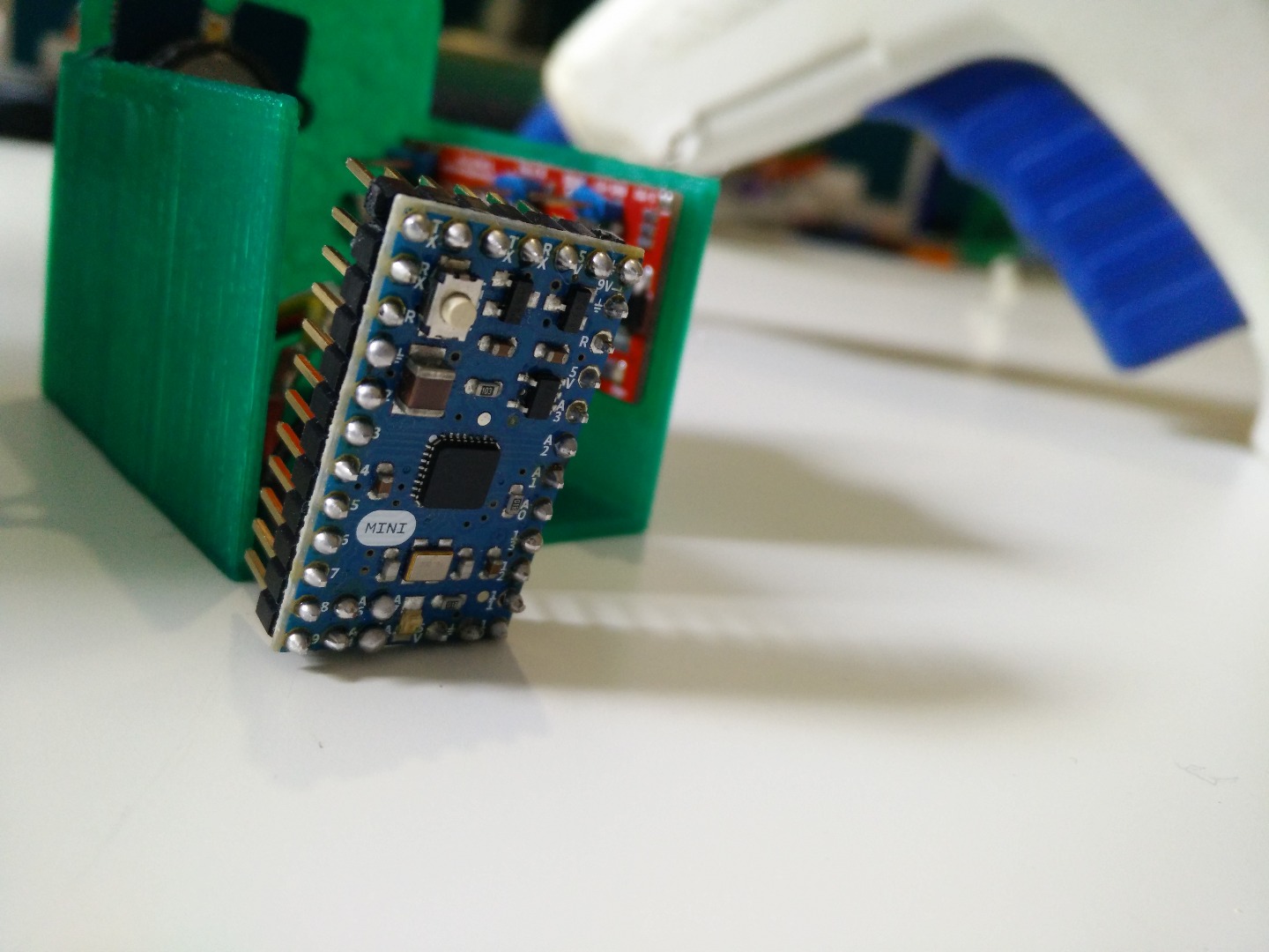
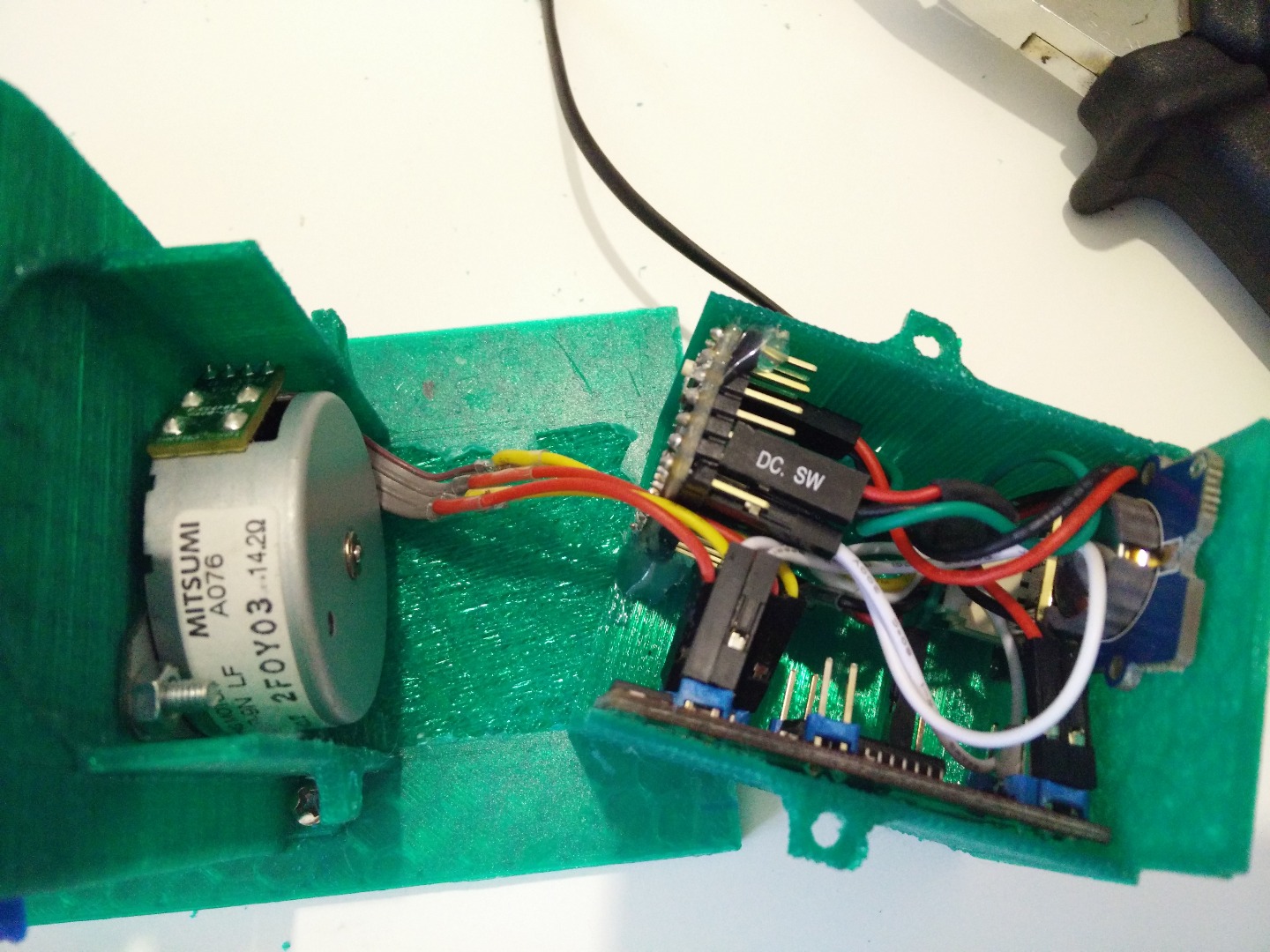
Preparing the Electronics
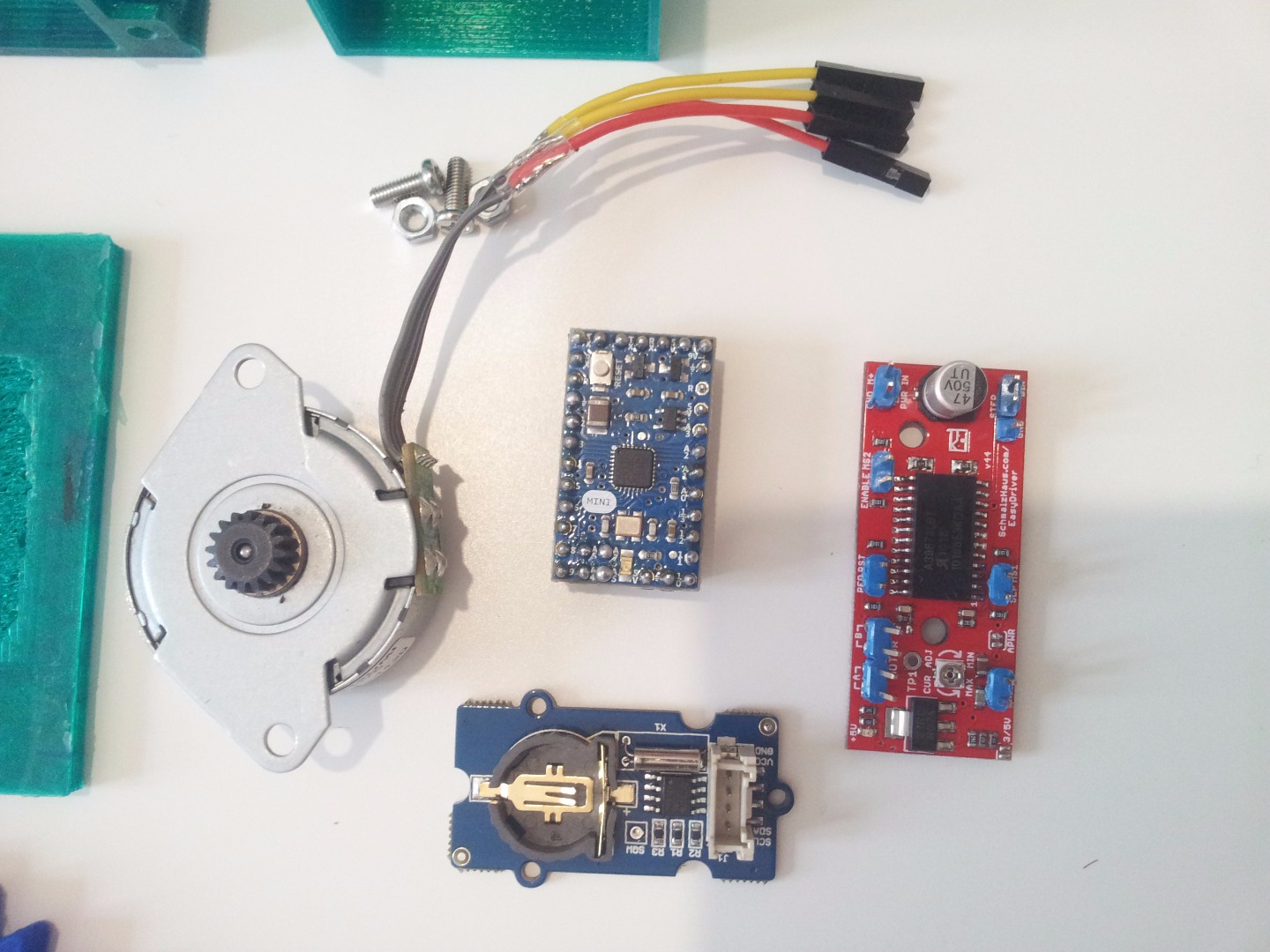
All the electronics used in this project are easily to find, and there's a ton of examples and tutorials about how to use them, so this should be easy.
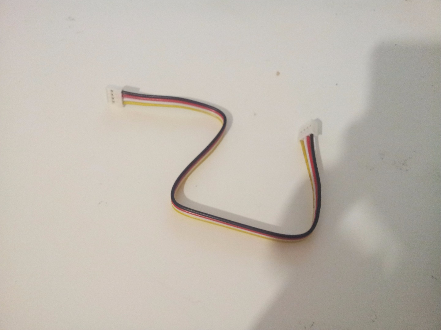
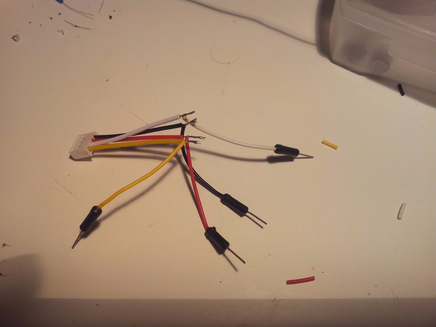
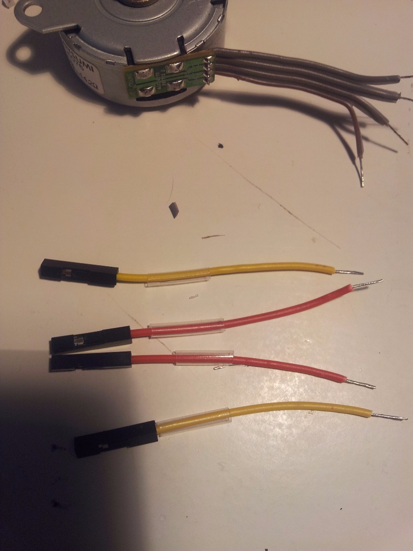
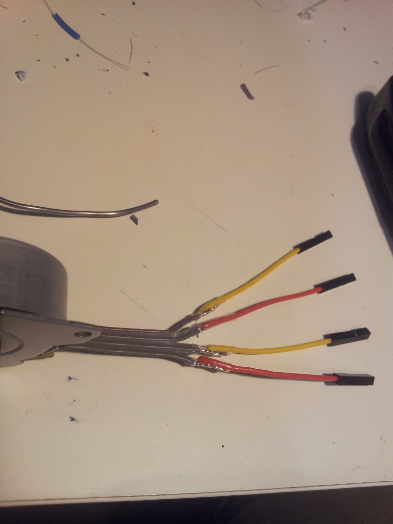
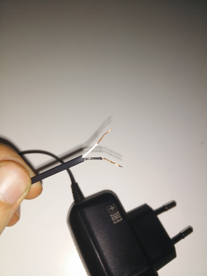
- Cut the cables to the correct length
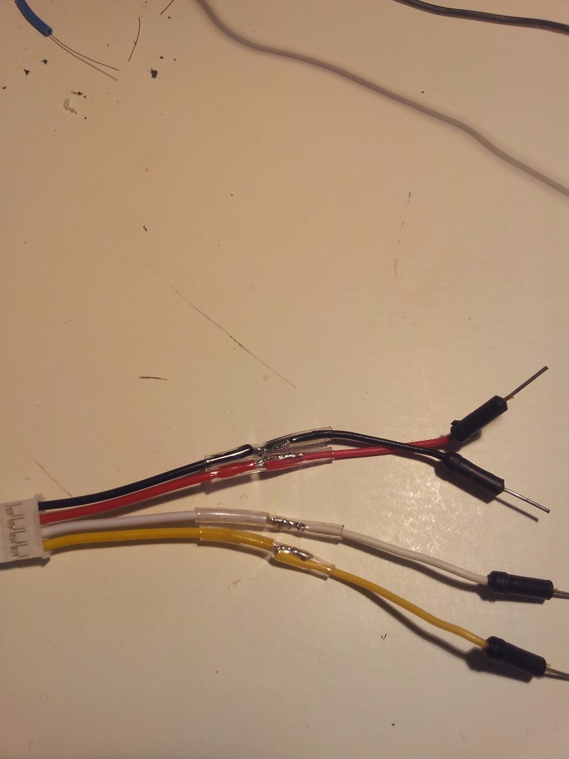
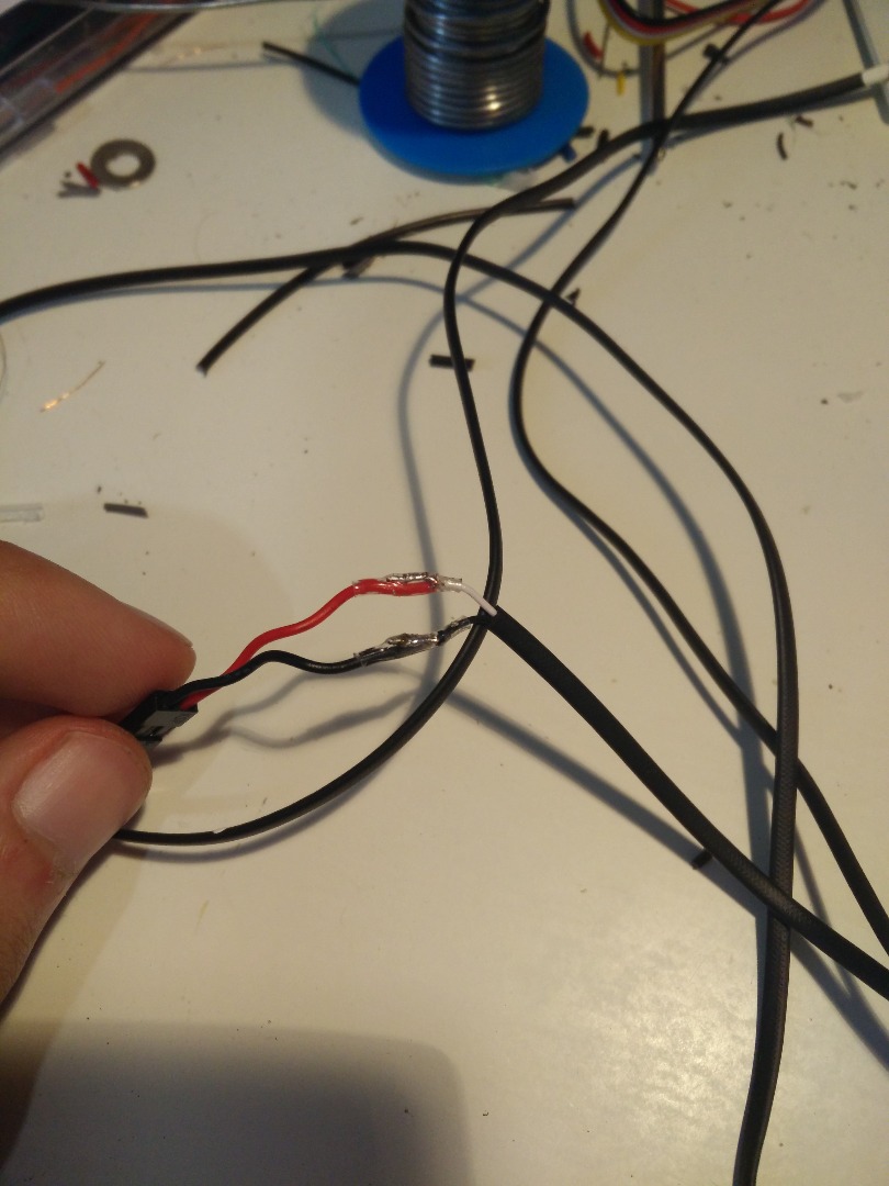
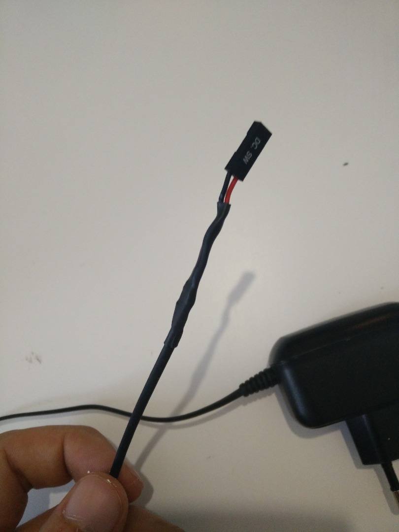
Solder all the headers
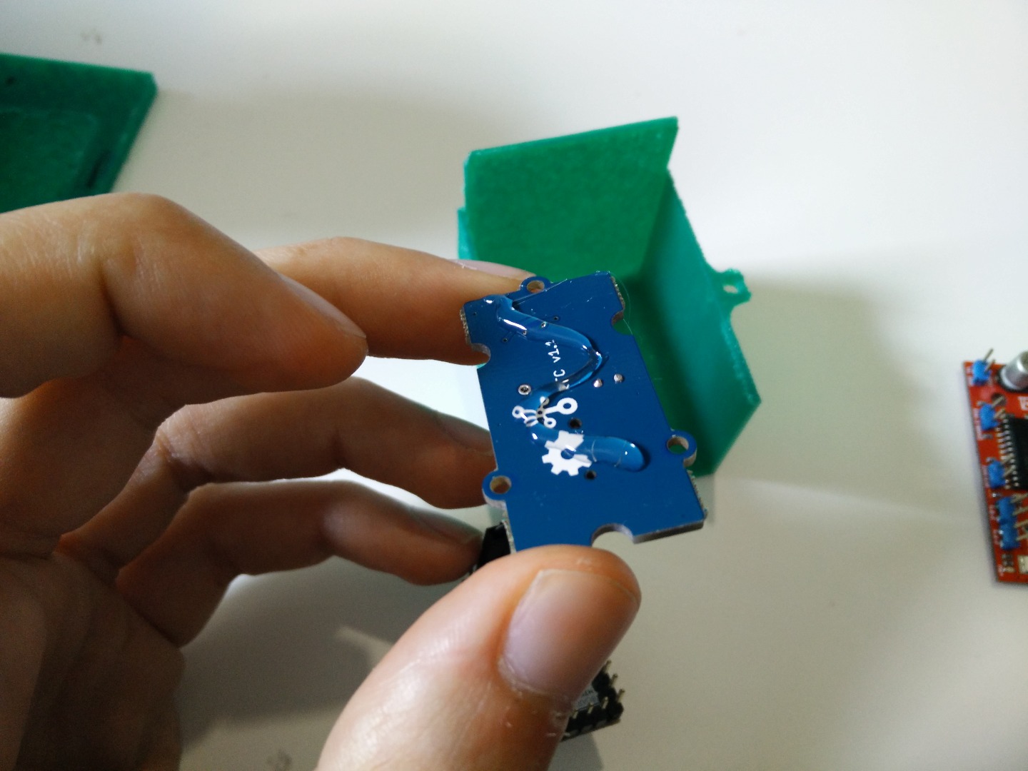
Buy a battery for the RTC (mine doesn't work without it). You need a 3V CR1225 battery.
Don't forget to isolate!
Then you have to connect them all together.
| RTC | Arduino pin |
|---|---|
| SCL | A5 |
| SDA | A4 |
| EasyDriver | Arduino pin |
|---|---|
| dir | 3 |
| step | 2 |
Obviously, don't forget to connect Vcc to +5V and GND to GND ;)
Power Supply
12V 1A power supply. A dream.
Unfortunately, the Arduino Mini has a voltage regulator that can handle up to 9V. So you have several options:
- Power everything with 5V. If you have a tiny motor, like me, 5V are enough, since the motor doesn't need to produce high torque to spin.
- Use a 9V power supply. You can connect it directly both to the Arduino and the EasyDriver. Be careful! 9V in the wrong place can blow everything up! Or simply burn the Arduino.
- Use a 12V power supply and a voltage regulator. I don't want to make a voltage regulator. But you can! Simply be sure that it fits inside the electronics housing.
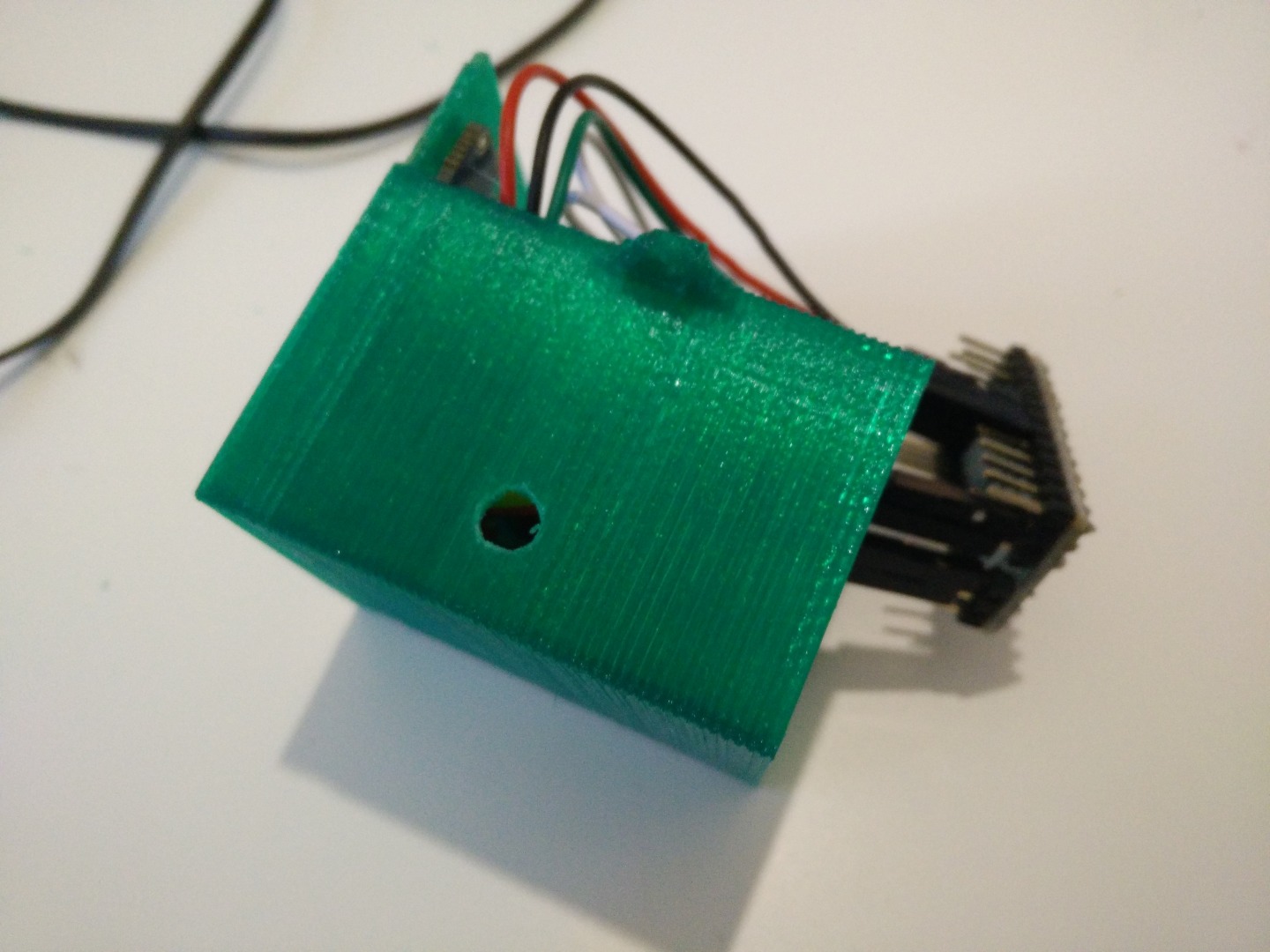
You may have noticed that the electronics' box has no holes for power supply. This is not an error. I did it so everyone can put the hole in the most convenient place for him, depending on his power supply and the orientation of the clock.
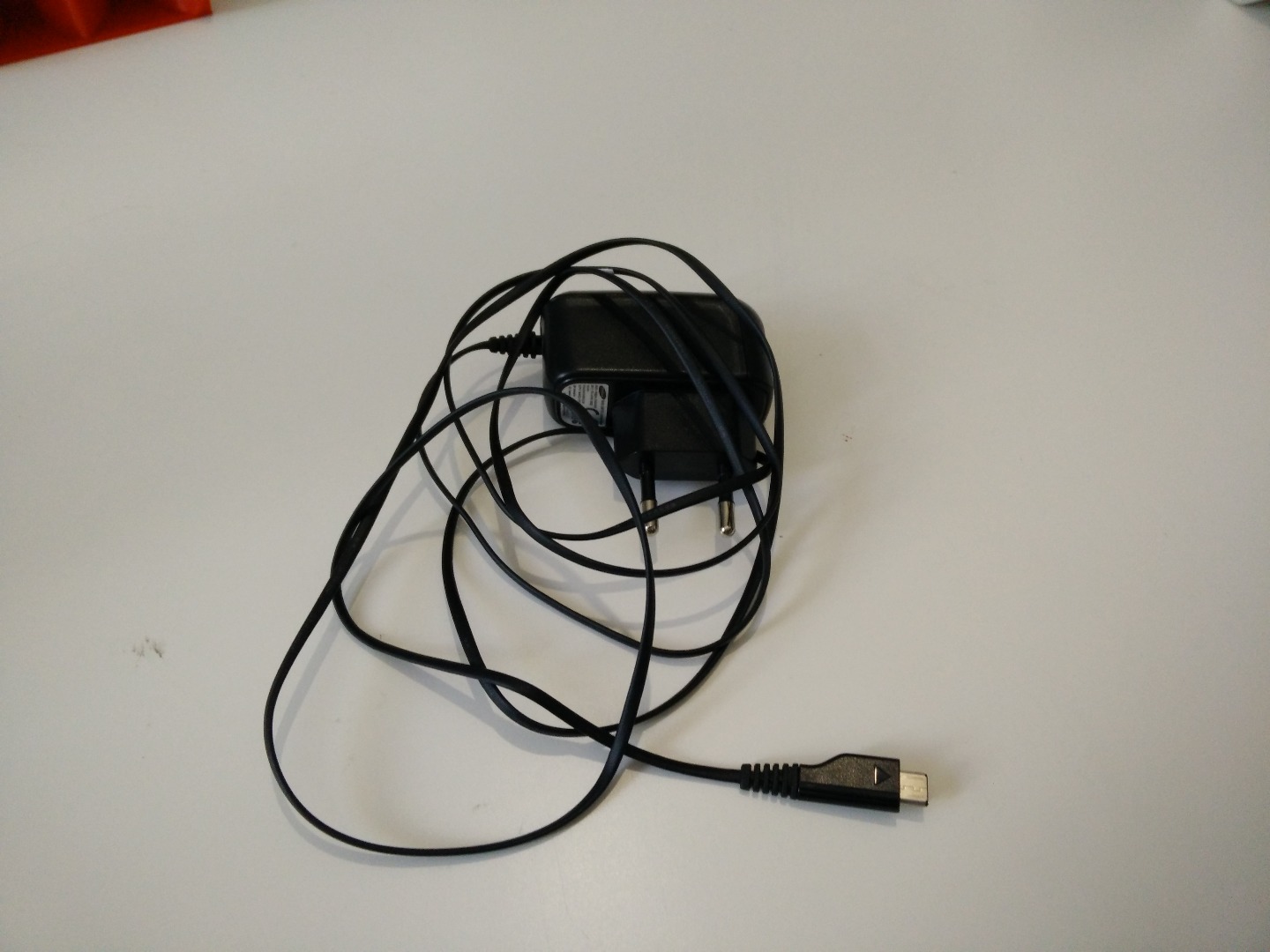
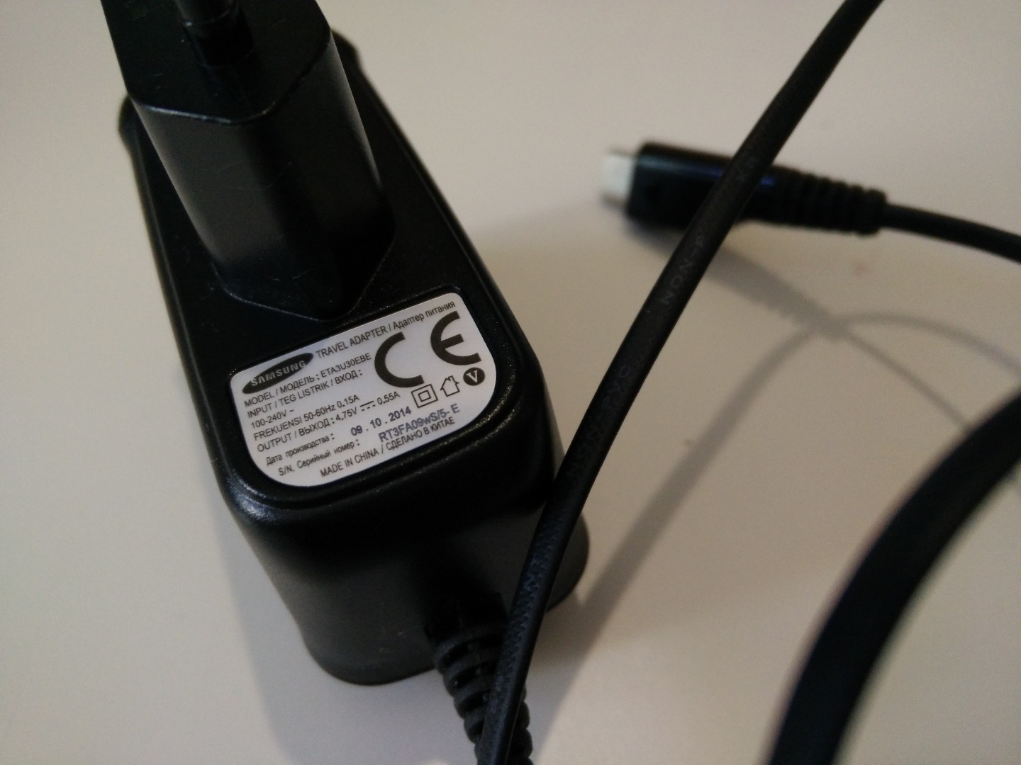
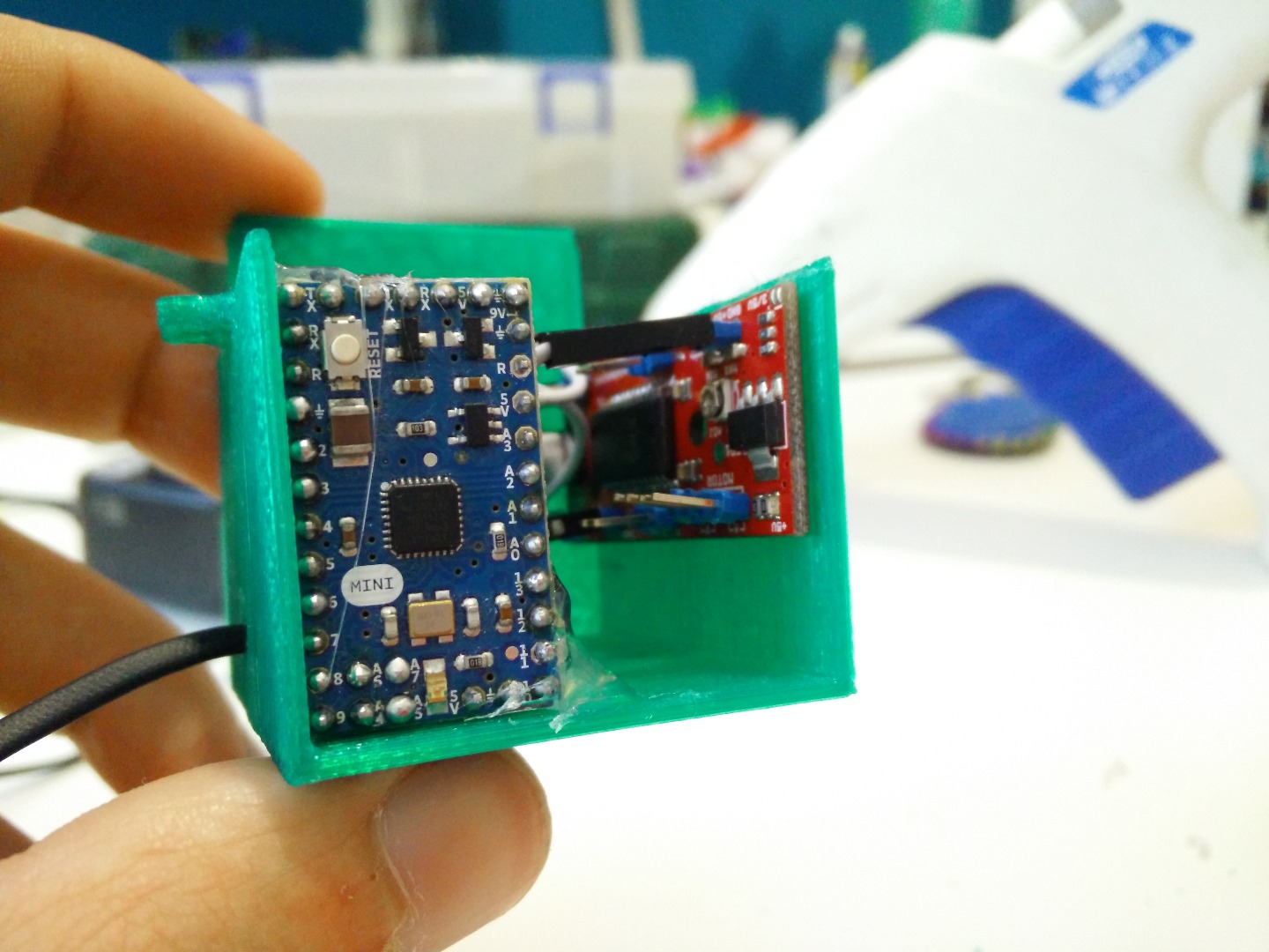
I decided to run everything on 5V, using an old charger, so everything is in parallel. You can see the one I used in the pictures.
Initializing the RTC
Before you flash the sketch that will run the clock, you have to set the time on the RTC. You do this by running the "SetTime.ino" sketch you find at the end of this sketch. This is very important otherwise the RTC wont answer your calls.
Wire the RTC with the Arduino (you can also use another Arduino) and run the Sketch. It will take the time from your computer and set it on the RTC.
Don't forget to insert the battery!
Downloads
Programming
The programming part is very easy. If you don't know how to program your Arduino Mini, you should just search here on Instructables, there's a ton of examples.
To make it work properly, you have to set a couple of parameters:
- The time in seconds that the firmware has to wait before refreshing the time on the clock. If you set it to 30, it means that the clock stays for 30 seconds and then rotates of half a minute. Default is 60 seconds.
#define REFRESH_RATE 60 //how much time between a rotation and the other?
- Comment this line (by adding // at the beginning) if you want your stepper driver always on. If the driver is always on, the motor may produce some tedious noise and also get pretty warm. I suggest to leave this line uncommented and connect the enable pin to the Arduino, is the best choice.
#define use_enable_pin
- The number of step your motor has to do to complete one turn. Usually it is 200 or 400, but it may also depend on your stepper driver configuration.
#define STEPS 400
- Set the "direction" parameter to -1 to invert the rotation of the motor. Do this if when you switch on the clock it rotates in the wrong direction.
#define DIRECTION 1 // 1 <-> -1 set to make your motor spin in the correct direction
Here you find the sketch and all the libraries you need to make it work.
Downloads
Mounting! - the Rotors
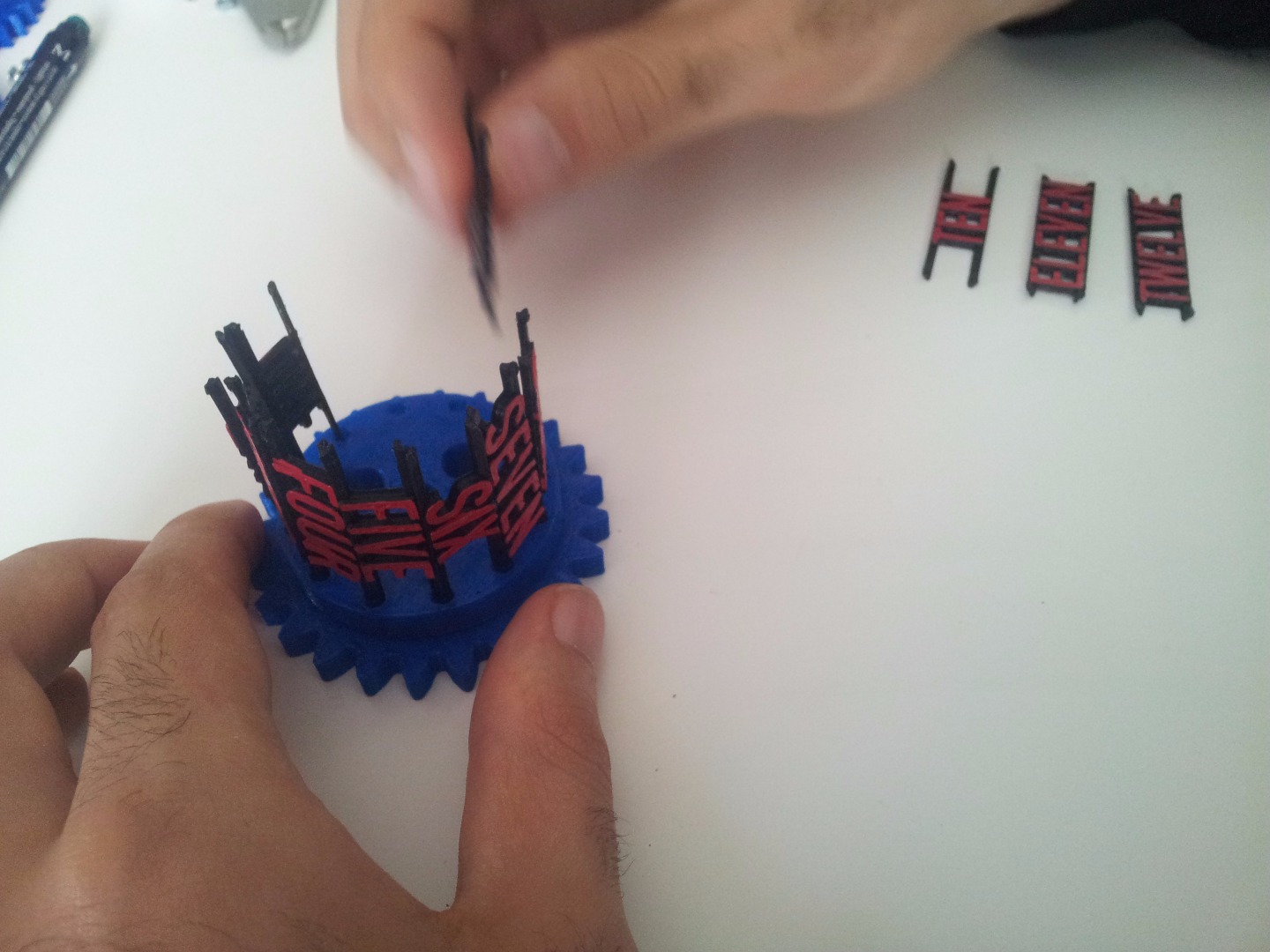
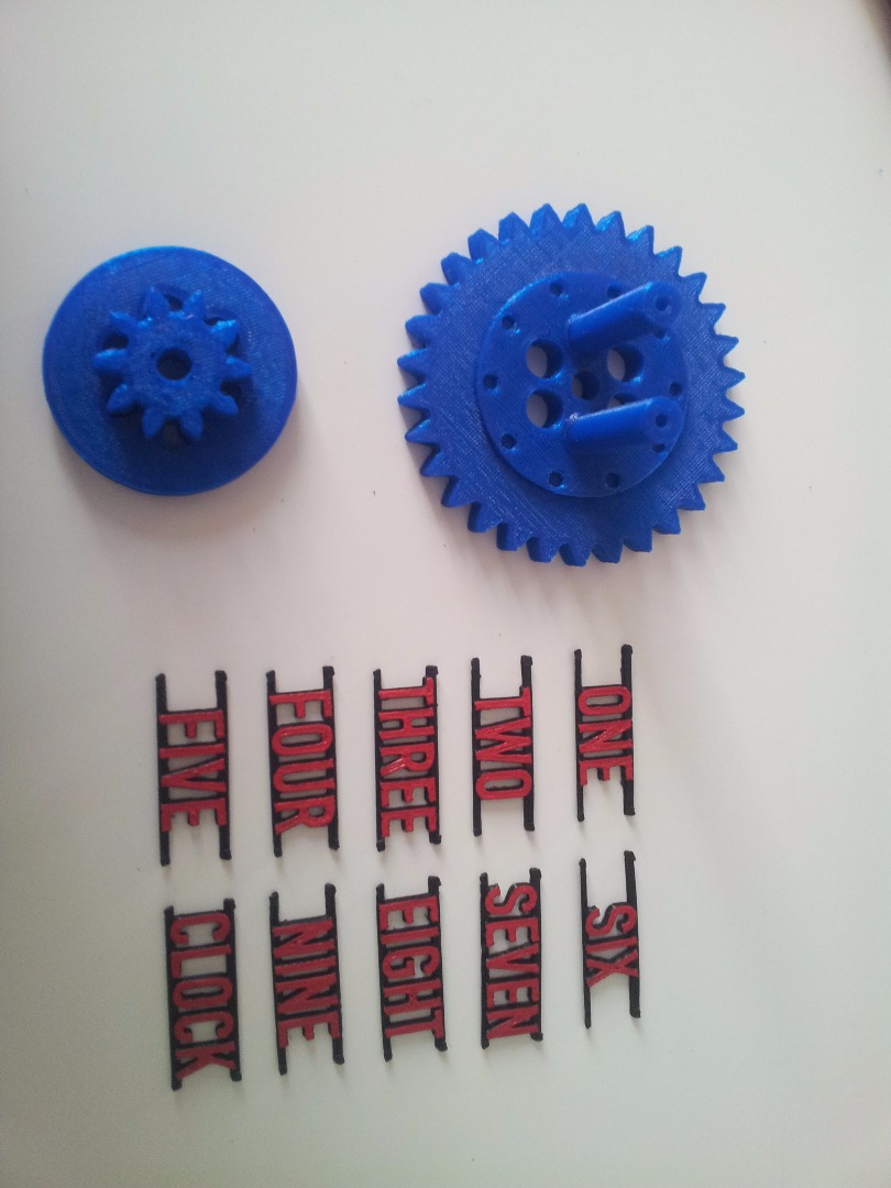
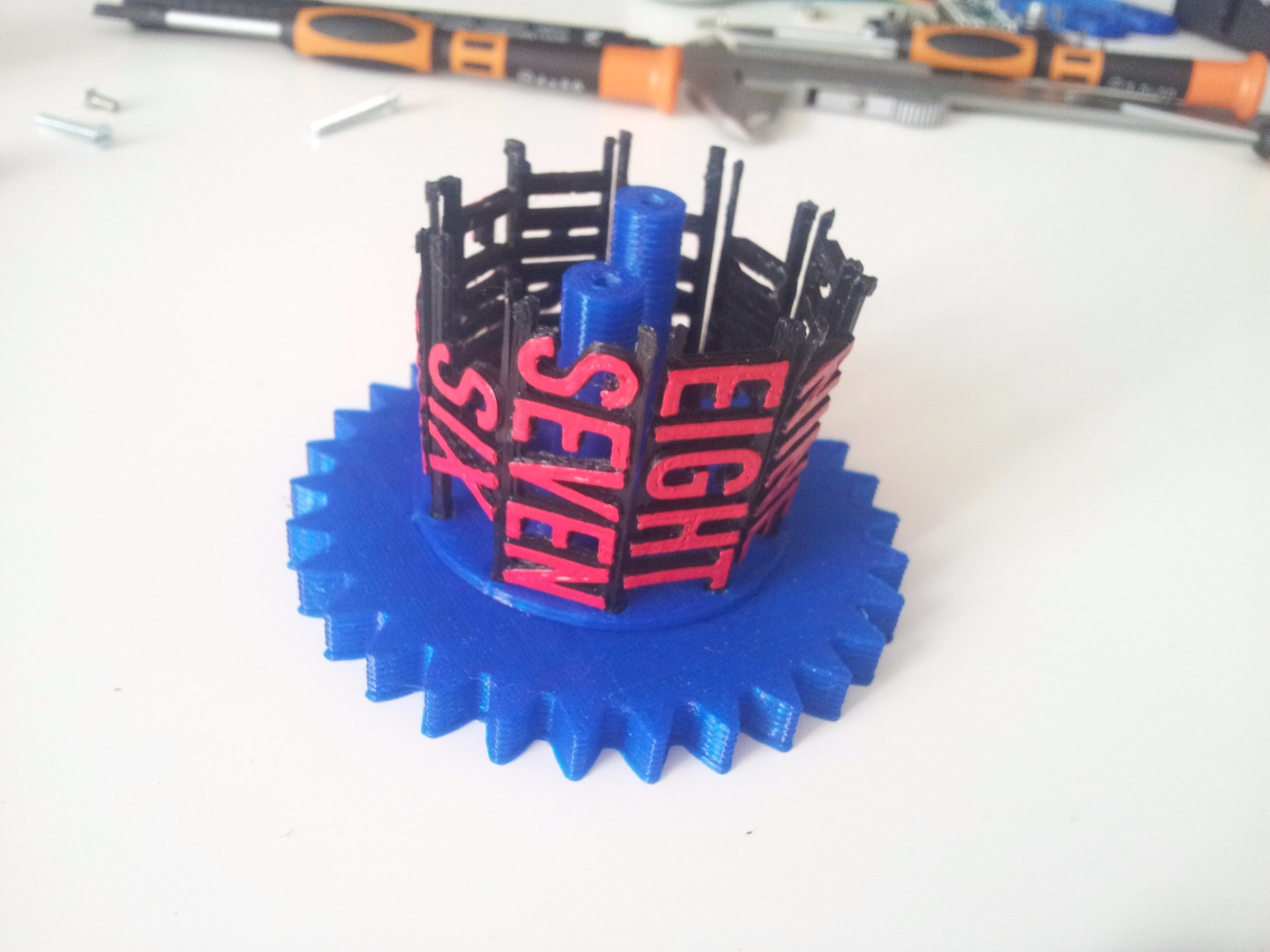
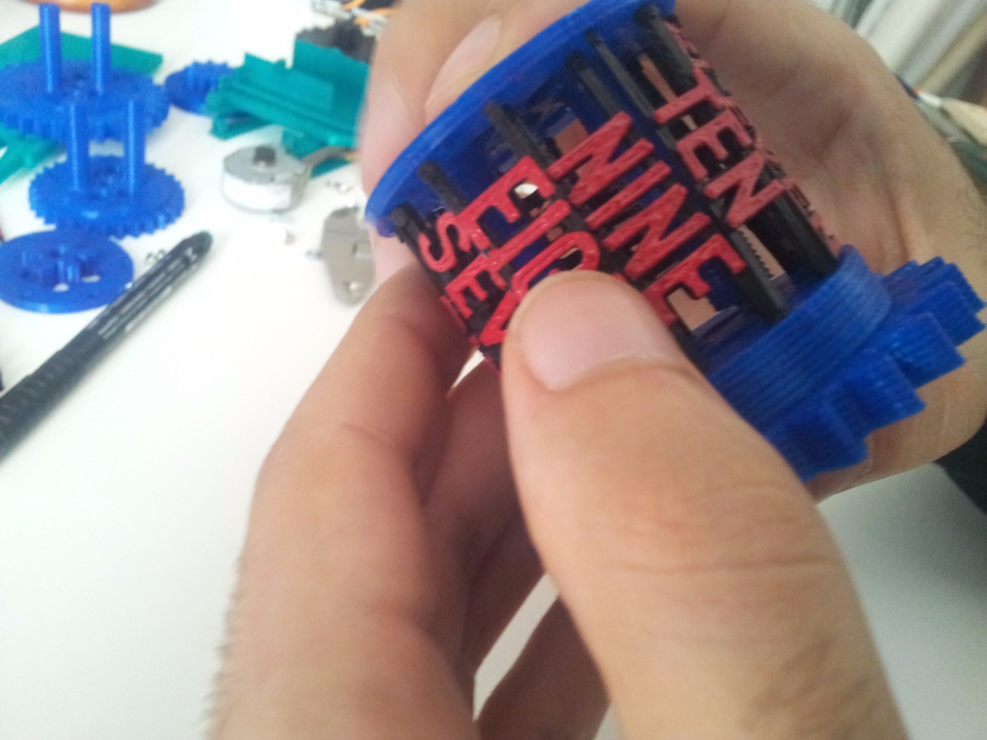
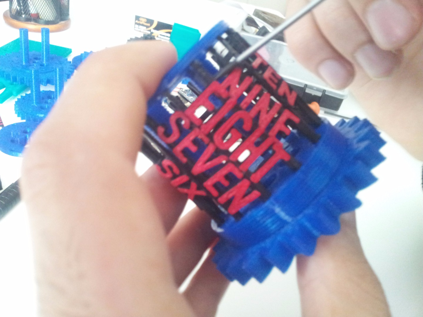
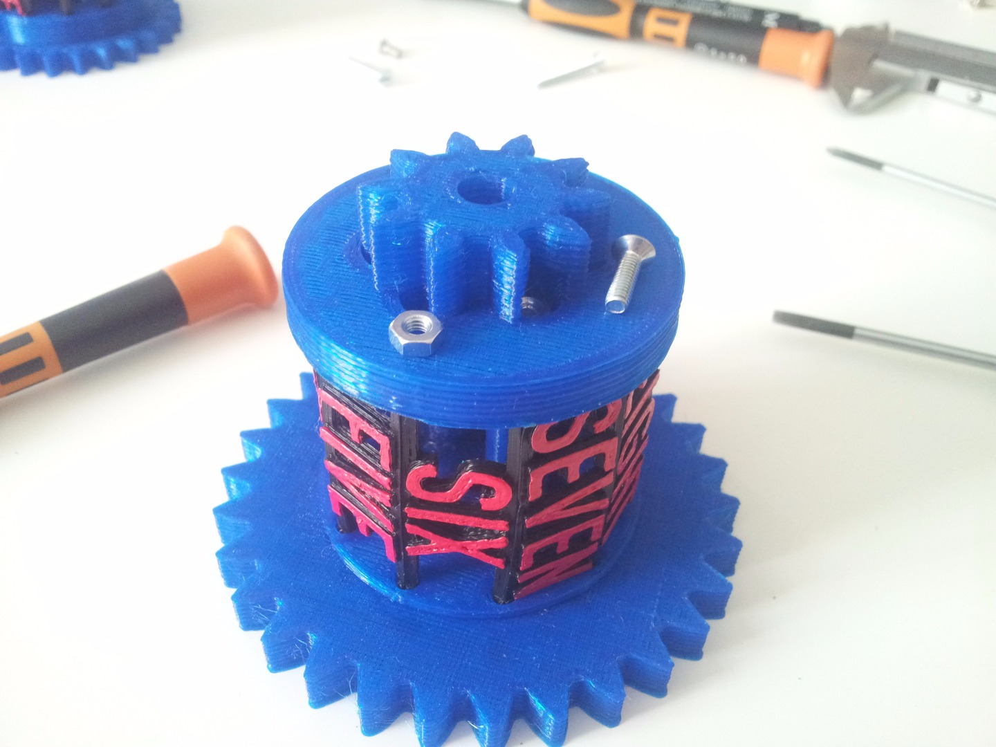
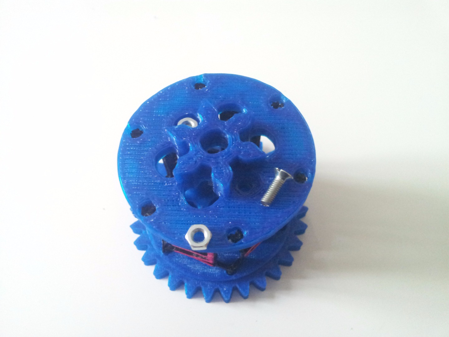
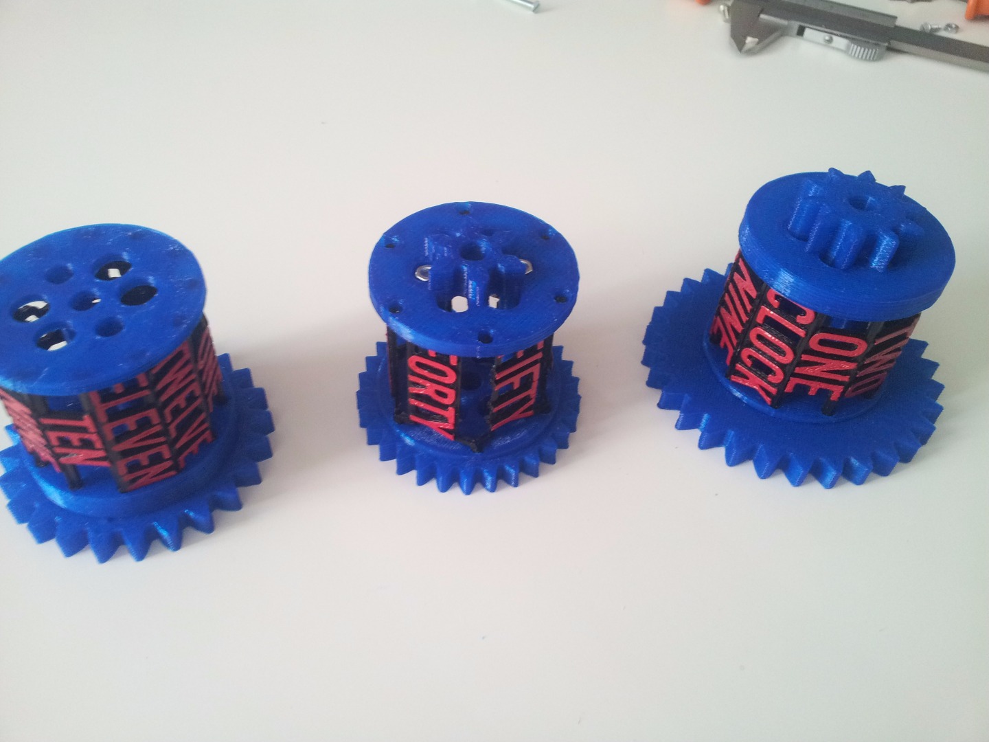
Put the geared half on the table and then, with patience, fit all the labels in the holes. Pay attention to the order!
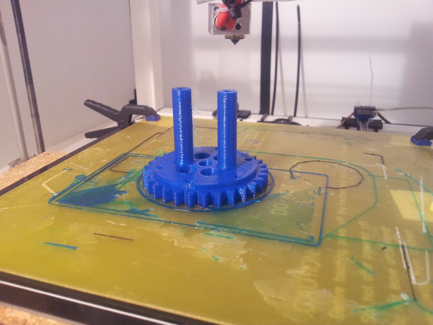
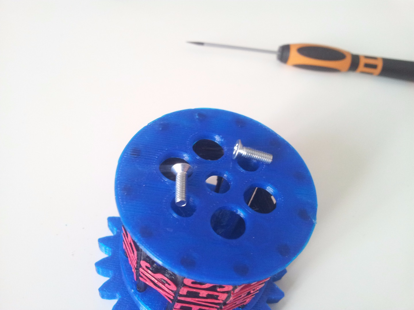
The middle rotors needs the two 6mm screws. Anyway, if you follow the photos you shouldn't have any problems.
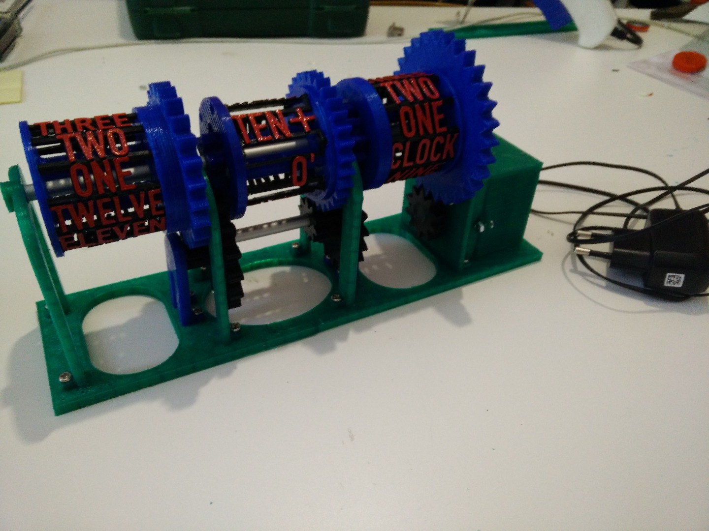
Mounting! - the Base
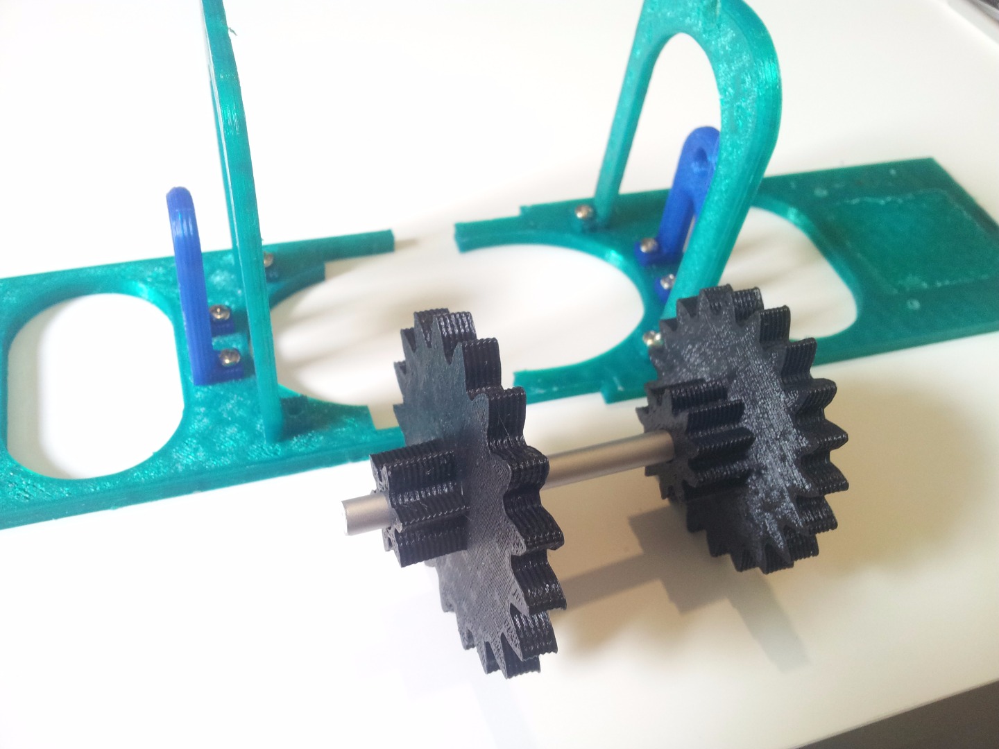
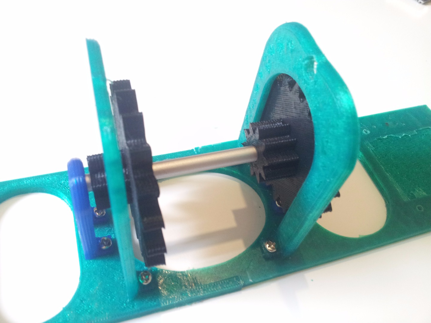
Screw the two middle supports (the green high ones) to the two half bases, paying attention to the orientation (the side with the holes has to point the middle of the clock). You also have to mount the left support (the one without the motor) on the base.
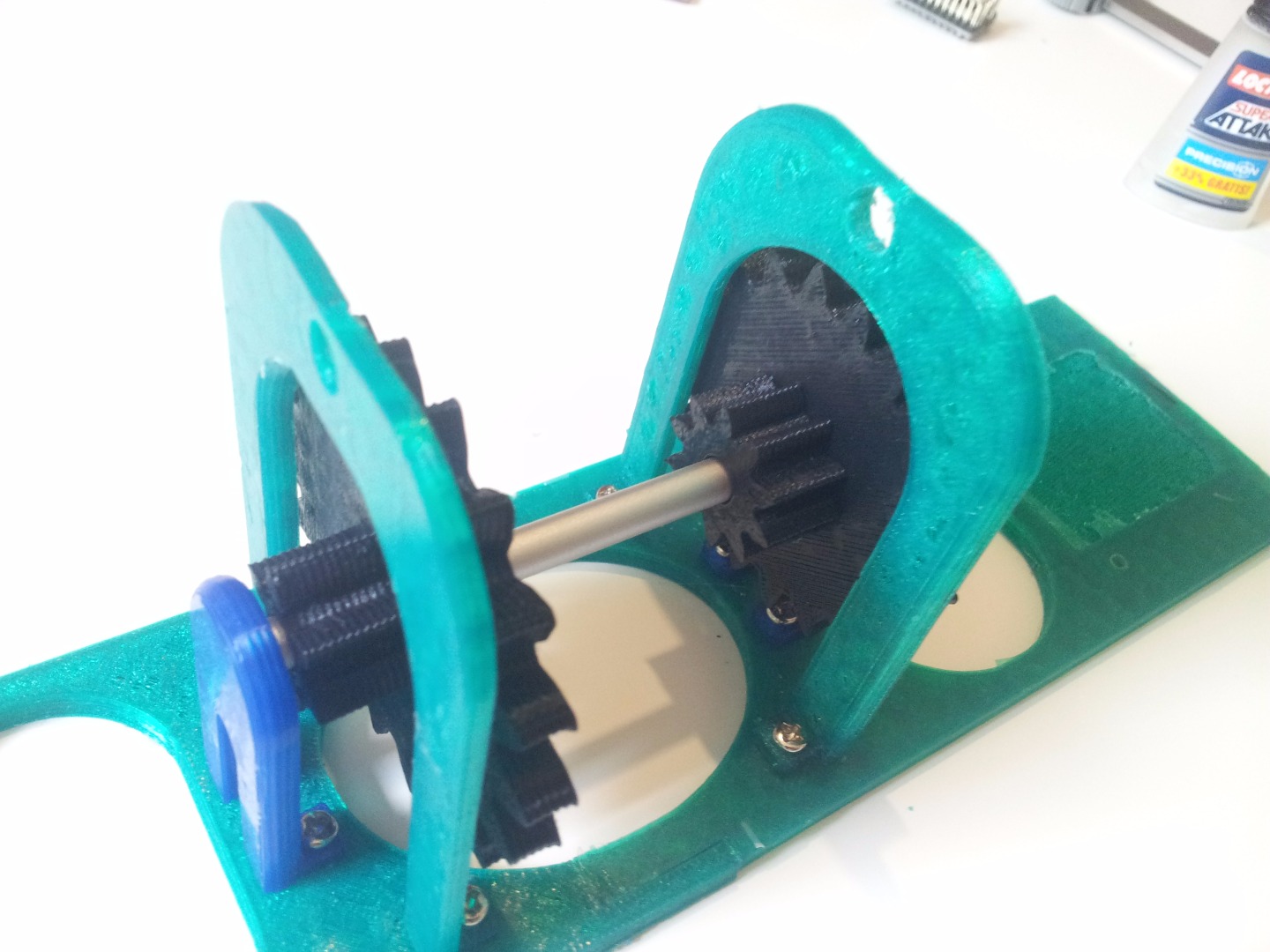
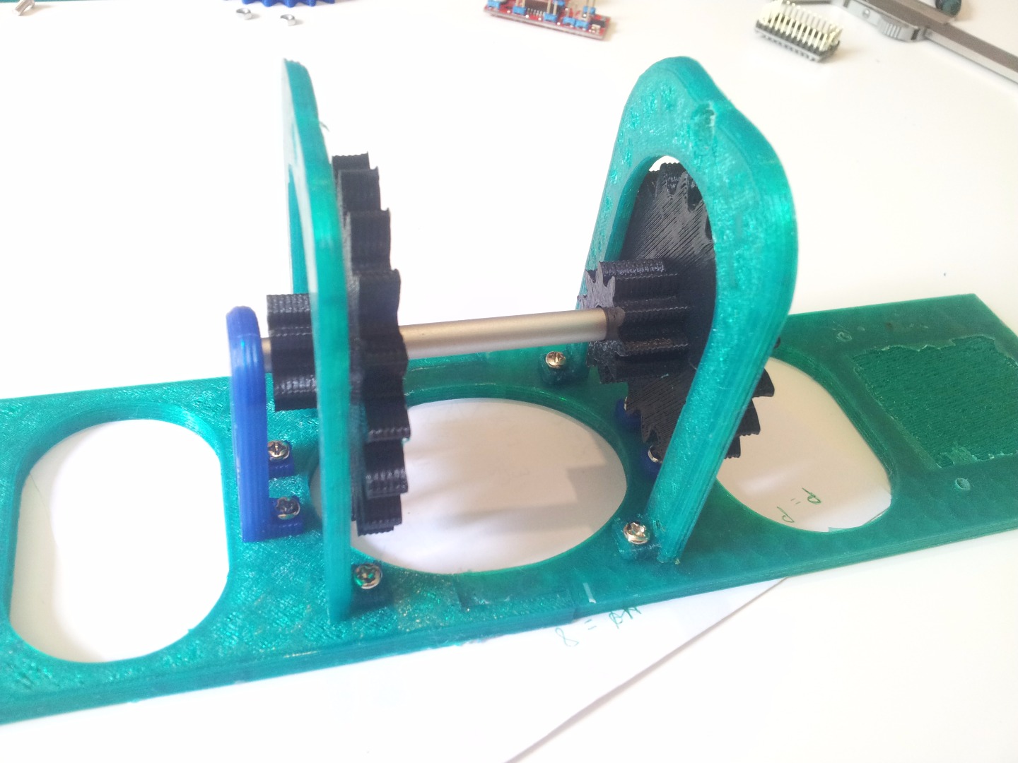
Mount also the two little supports (blue in my model). The two external supports will be mounted later. At this point, you have to position the short axis with the two transmission gears. Pay attention, because the two gears are different!! If you put them the wrong way... well, that would be a problem.
Then, glue together the two half-bases. Be careful to the alignment, if they are misaligned the clock wont work well.
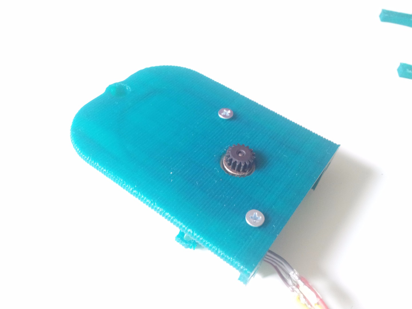
Now you can also mount the motor to the support and add the gear to the shaft. There are some considerations to do about this.
Considerations on the Motor Gear
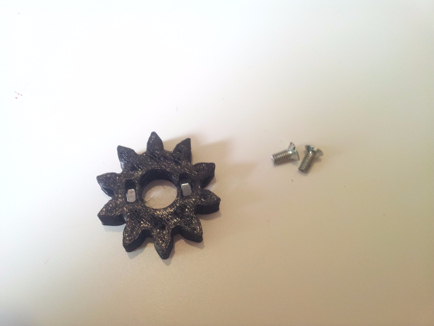
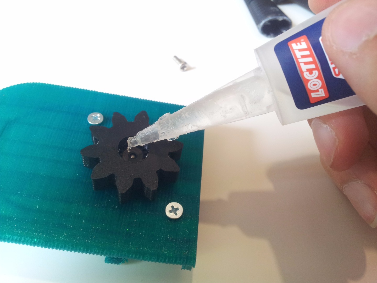
I designed the gear to be attached to the motor using two screws on it's sides. Seems logic. The problem is that my shaft was too short, so there was not enough space for the screws to grip on the shaft. This is not a problem if you have a longer shaft, in which case you can skip this.
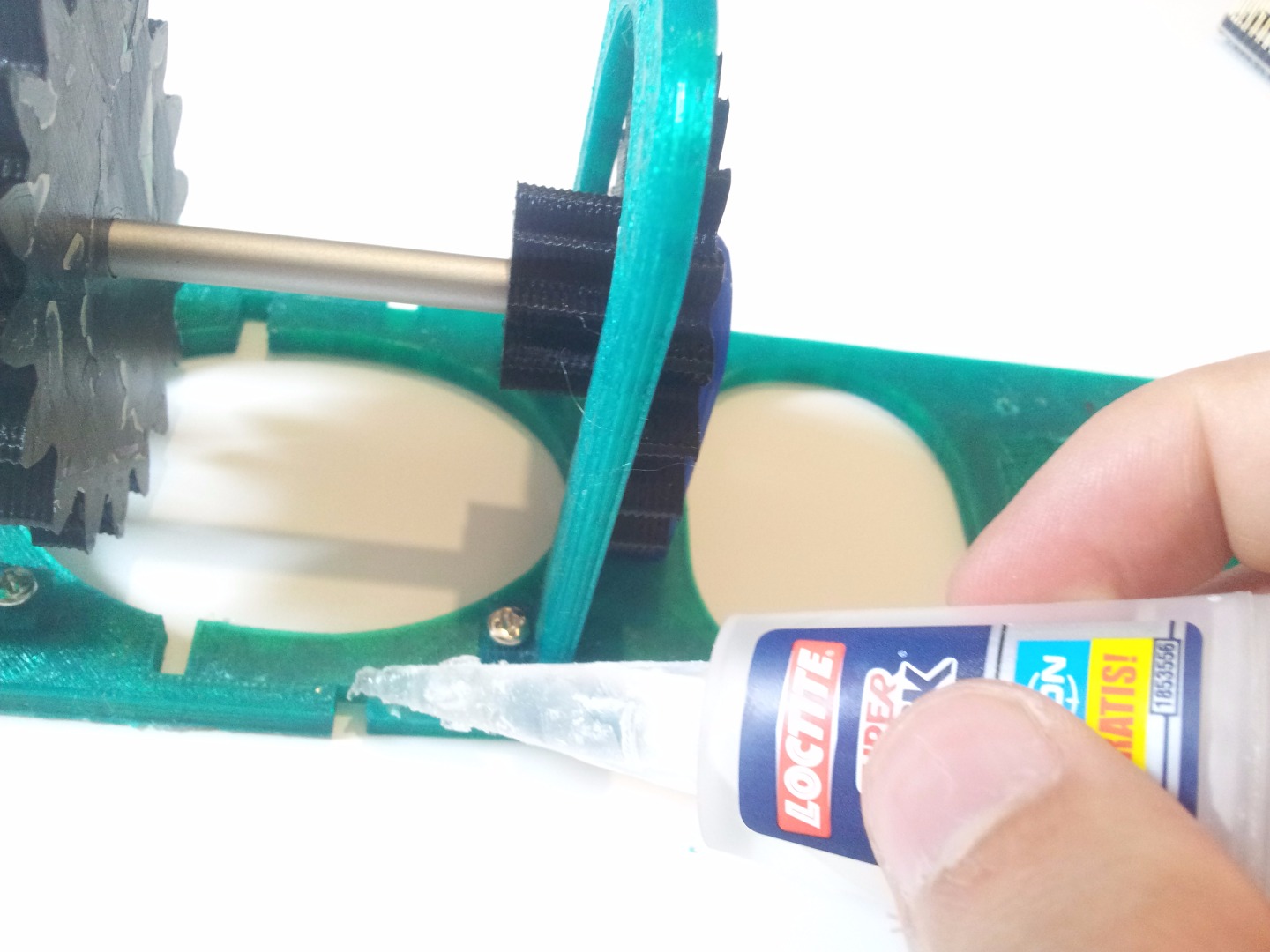
I tried to fix this by adding some super glue between the screws and the shaft, but still the contact surface was too little.
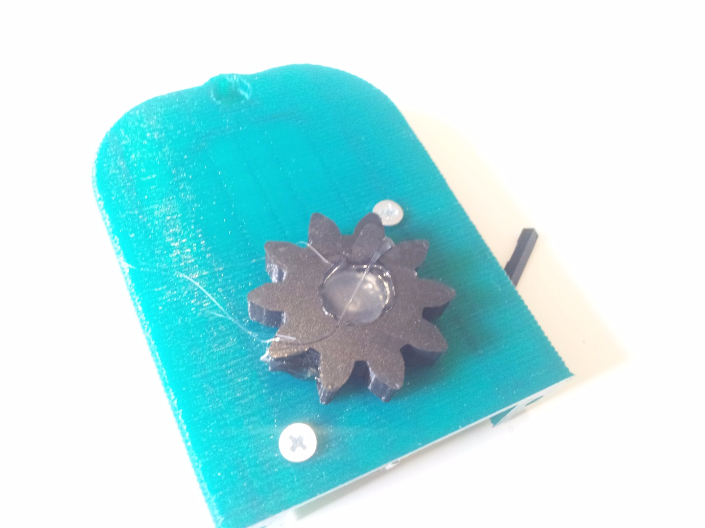
So I decided to try with hot glue, but it didn't work. The glue sticked perfectly to the plastic but not at all to the shaft. The solution was to add some super glue between the hot glue and the shaft.
I know this is not elegant, but I have no other steppers at the moment (not so little) and the result was good anyway (there's no visible difference).
The only elegant solution would be to have a motor with a longer shaft.
Remember that you have the blank gear (step 4) so you can make it fit your motor.
Mounting! - Everything Else
Now you have to add the rotors and the two end supports.
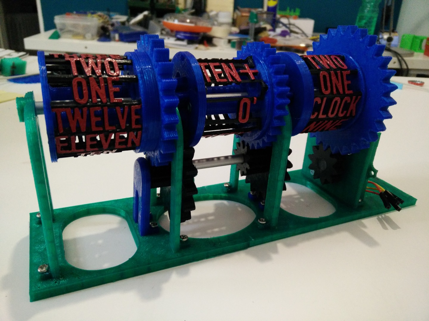
Put in place the middle rotor and then make the axis slide through it. Rotate the rotor until you have the O' label facing at you. This is very important because once the clock is mounted, you can't change the relative rotation of the rotors any more.
Now position the left rotor with the TWELVE label facing at you and slide the axis again.
Make the same operation with the right rotor, and don't forget to properly orientate it! Obviously, this time with the CLOCK label facing at you. Now you can position the motor support and you are done :)
Try to spin the clock with your hand, it should move pretty smoothly.
Every six turns of the right rotor, the middle one has to complete one turn, and you have to find the next hour perfectly (more or less) aligned with the O'CLOCK labels. If the rotors wont turn or the alignment is wrong, there are three main hypothesis:
- the axis hole of the rotors is too tight (due to printing imperfections) (step 3)
- you put the transmission gears in the wrong order (step 12)
- the rotors where mounted misaligned, in which case you have to remove the left and right rotors and remount them, with more attention.
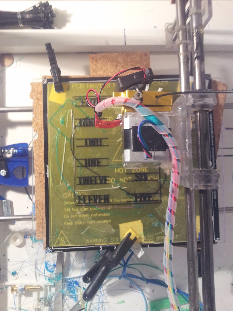
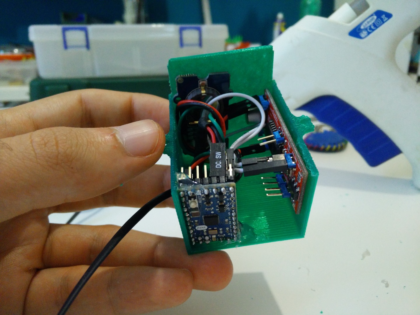
Housing the Electronics
The best choice would be to screw the board to the box, so you can be sure they won't move. There are two reasons why I didn't do so:
- Probably your electronics are not the same as mine. And the holes would be useless.
- I think it was horrible. I made a test, but the result was simply ugly, with all those screw coming out of the box.
So you can:
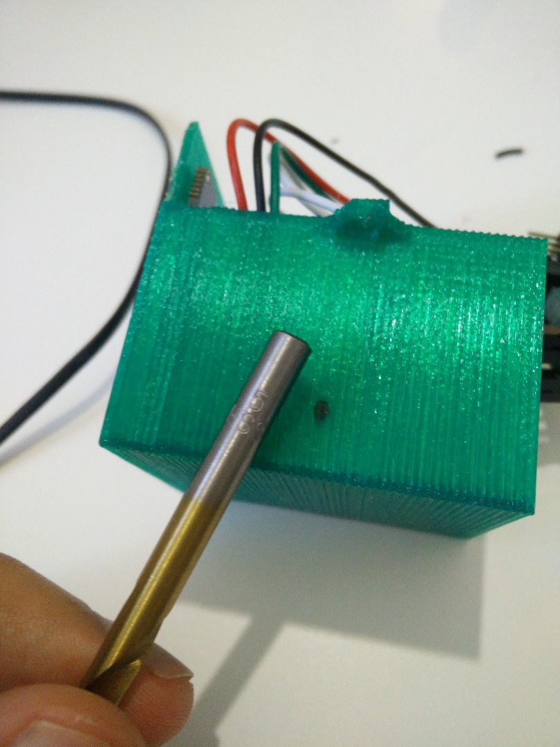
- Drill your holes.
- Glue the boards.
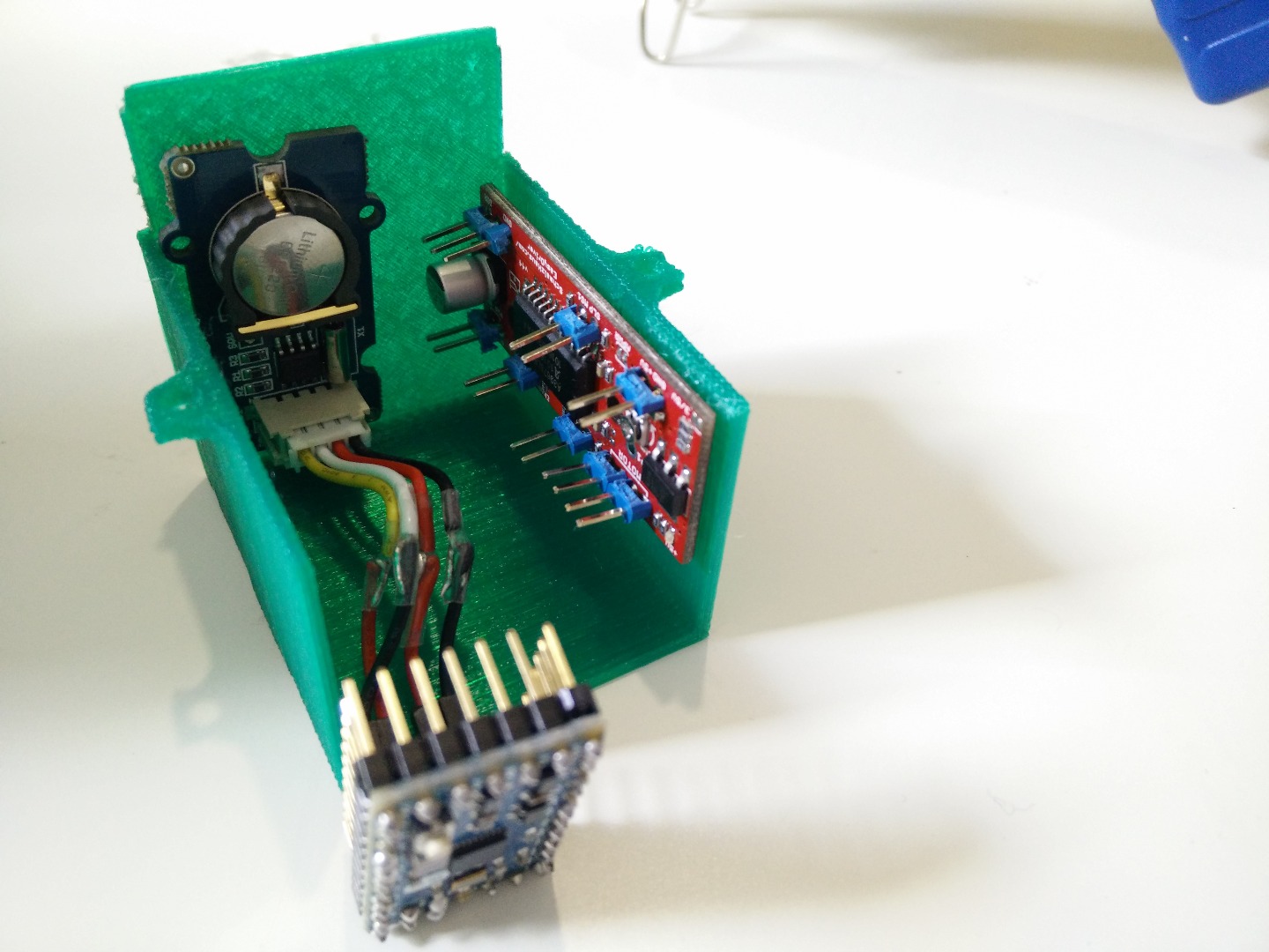
I choose the second one, and attached them with some hot glue.
Don't put hot glue on the chips that get warm. They would get warmer. The glue would melt. A big mess.
Seriously, pay attention to this detail, the hot glue is really insulating so the chips may get really really hot.
If you have the same boards I have, just look at the pictures for the disposition. Otherwise, it's like solving a little puzzle.
Set the Time
You have two options:
- Do it manually
- Do it automatically
If you want to set the time manually, you have to short the pin 13 to +5V. This will make the clock to simply spin when you plug it in.
If instead you want it to be set automatically, you have to short the pin 13 to GND. The clock must be set to TWELVE O'CLOCK, otherwise the program will not know the starting point, thus the finish point will seem random. Then, just plug in the clock and watch it setting itself to the correct time :)
If the time is wrong, check if you did correctly set the time on the RTC (step 9).
Done :)
Your clock is complete!
I hope you enjoyed this instructable as much as I had fun while making it :)
Sorry for my (absolutely) not perfect english, I hope the images can help you better than my explanations.
If you have any suggestions, feel free to write it in the comments!