3D Printed Pop Its
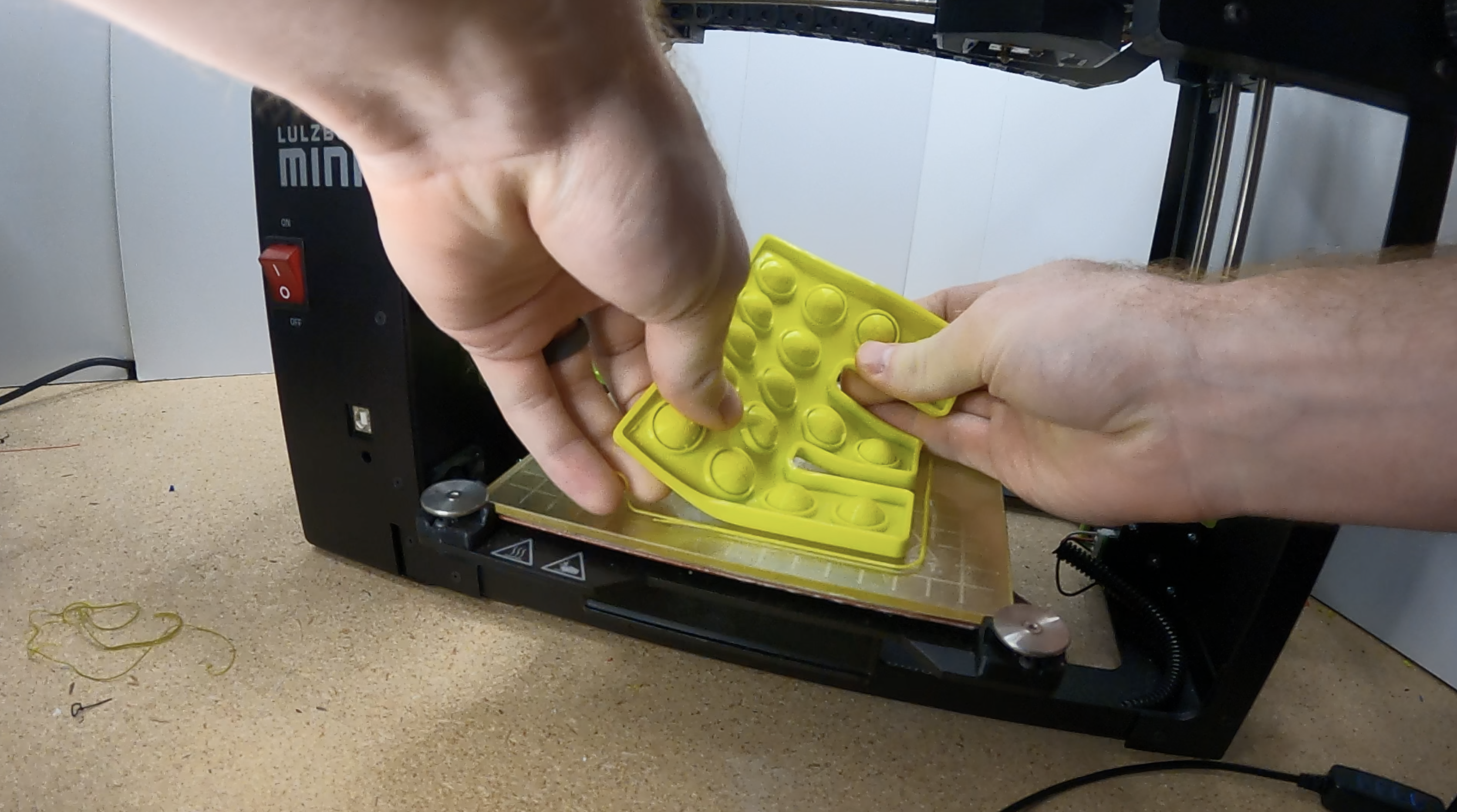
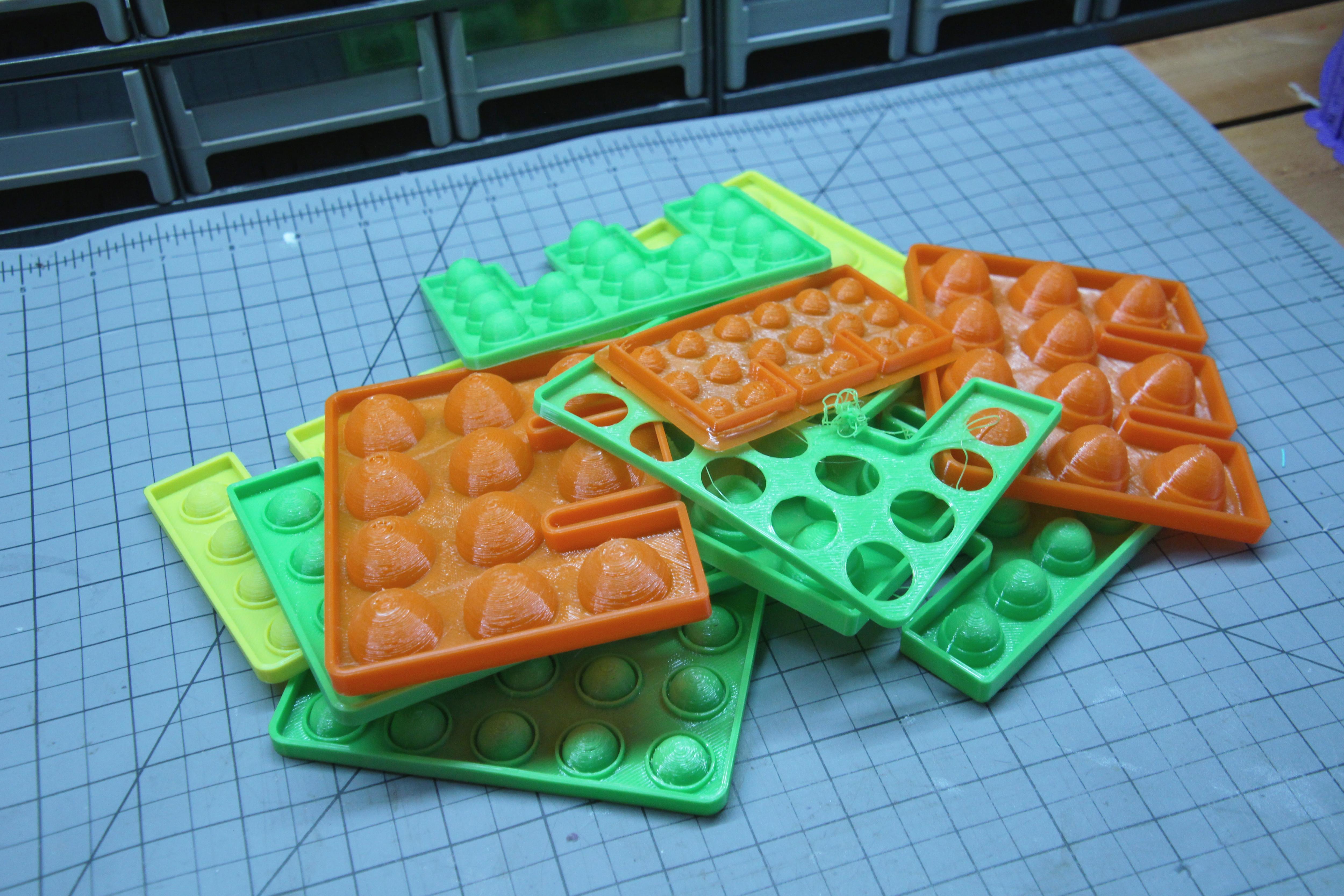
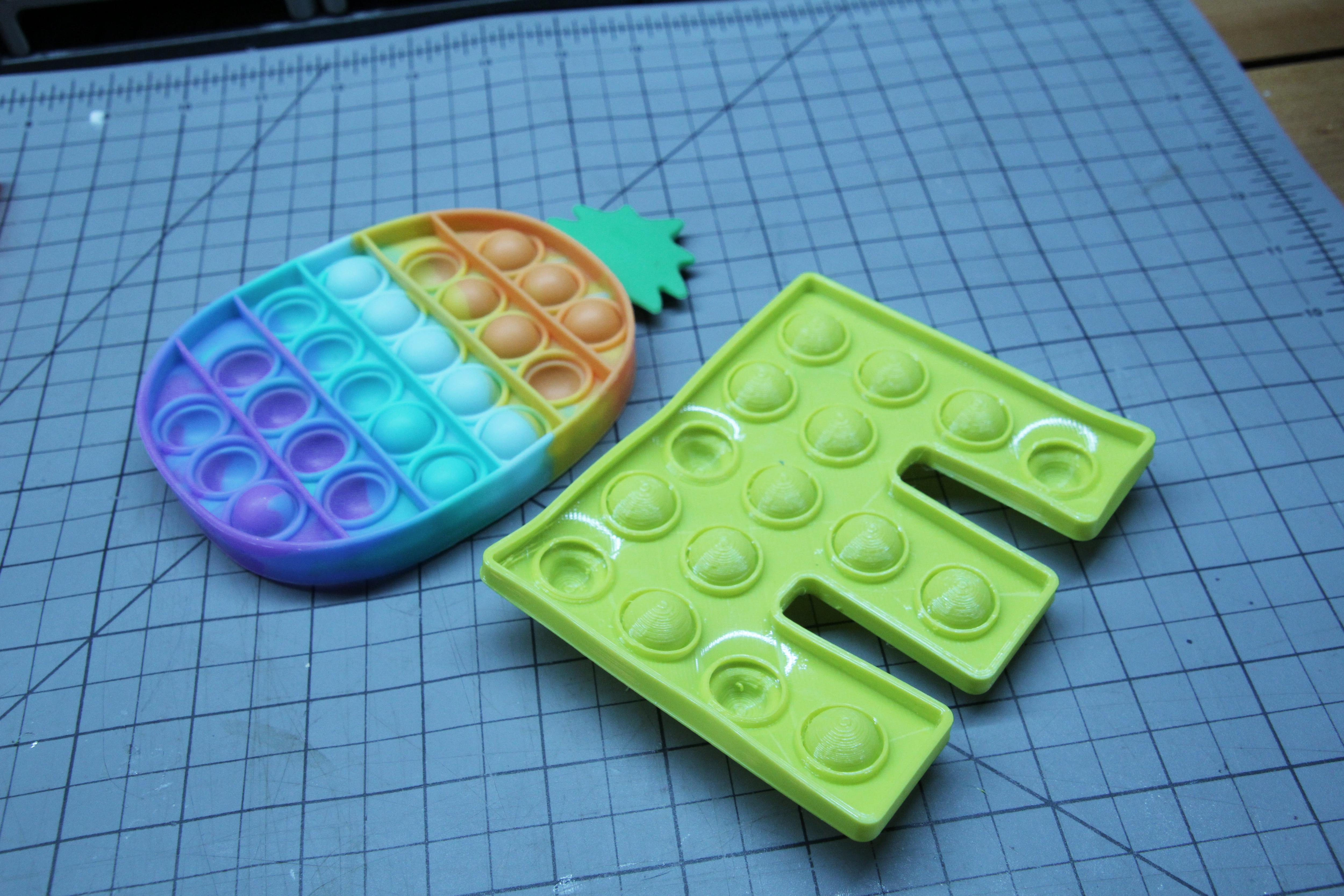
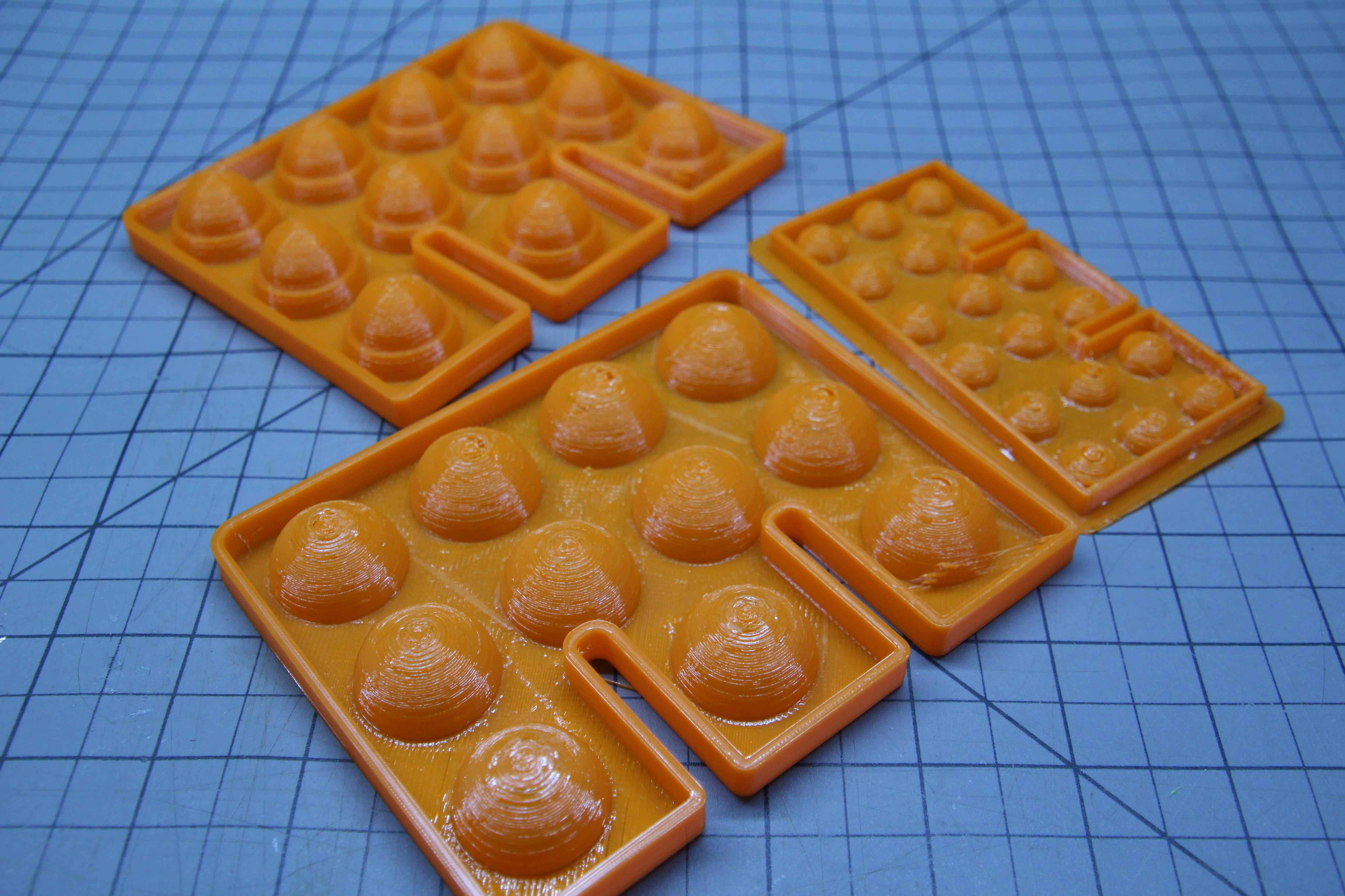
Pop Its have quickly become one of the most popular and entertaining fidget toys over the past year or so, and who can doubt why? Super squishy, endlessly entertaining, infinite designs, and really really cheap to buy! But I wondered, could these be 3D printed? The short answer is, yes!
Through lots of prototyping, I have come up with a solid design that is easy to design, simple to print, and durable to use. For modeling, I used Tinkercad and Onshape to create the pop it model, and I am using an extrusion-type FFF 3D printer with TPU filament for manufacturing. As outlined in this instructable and the attached videos, I tried a lot of different designs, worked through tweaking tolerances specific to the diameter of my nozzle and set layer height, and tried a bunch of different flexible TPU filaments until I found a result I was happy with and able to replicated. All the details are outlined in the attached links and steps within this instructable post!
Supplies
To create your pop it, you will need a CAD program to design it in. I recommend Tinkercad for beginners or Onshape for more advanced users. Both of these programs are free to get started with and work on any device through a web-based and collaborative interface! If you want to learn more about these programs, check out my training videos on my youtube channel here for Tinkercad or here for Onshape!
You also need a 3D printer that can print flexible filaments. I personally prefer LulzBot 3D printers and I used my LulzBot Mini 2 with the 0.5mm standard extruder print head for this project. I also used NinjaFlex 85a flexible filament.
CAD Tutorials
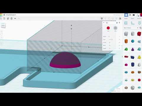
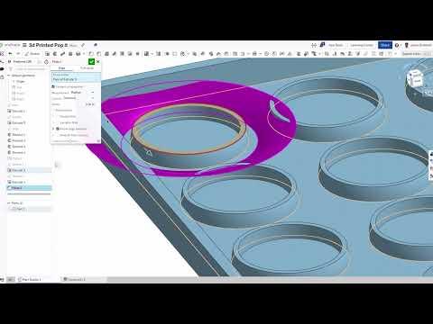
The first step in creating your own custom pop it is to choose a CAD program to design it in!
To assist in creating your pop it, I have created two tutorial videos that accompany the following steps to demonstrate how a pop it can be made in both Tinkercad and Onshape. There are infinite ways to design your own unique pop it, but I outline the methods and dimensions I used to have greater success with my prints in these videos. The following steps also outline these techniques in greater detail.
Creating the Base Shape
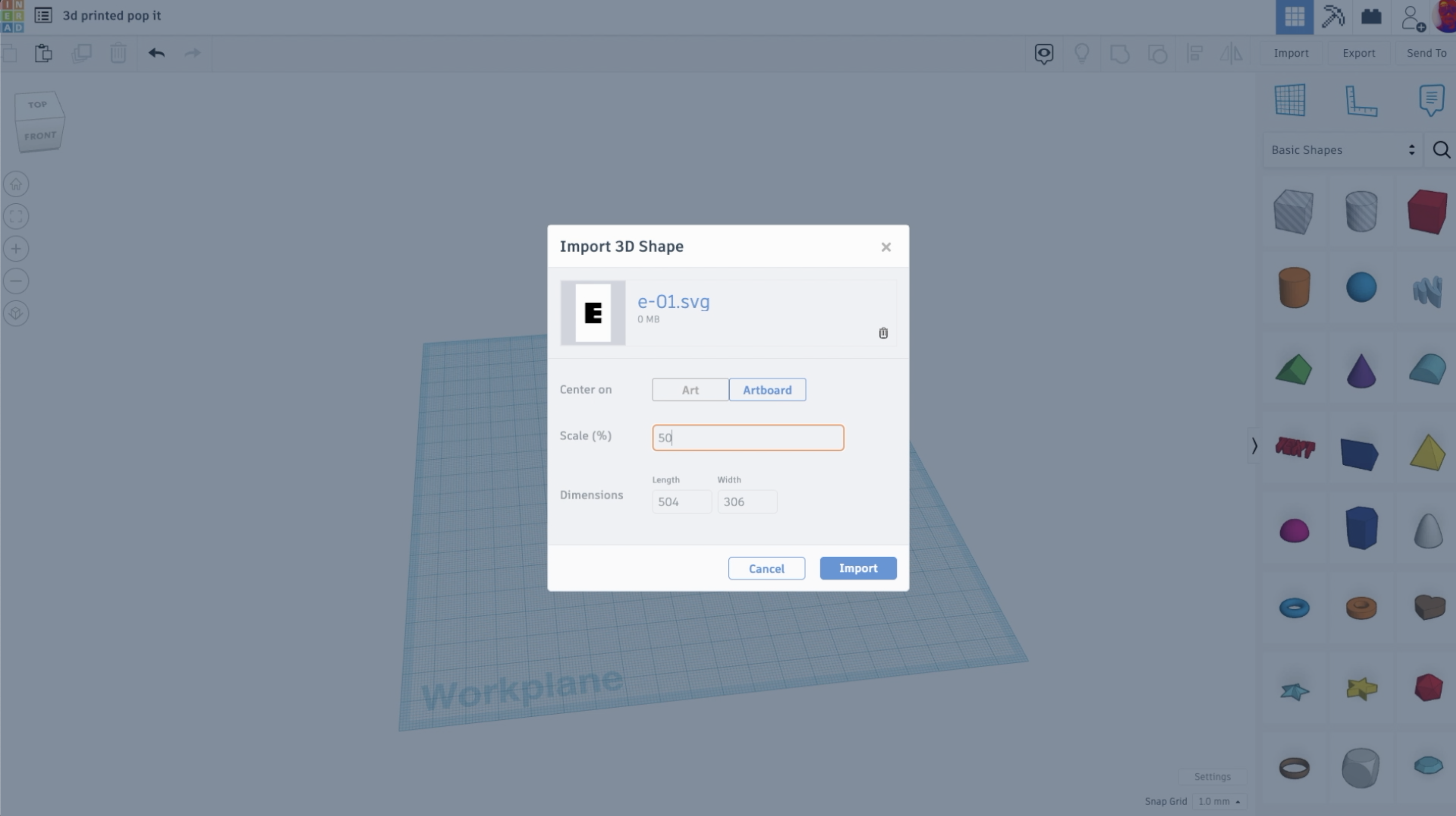
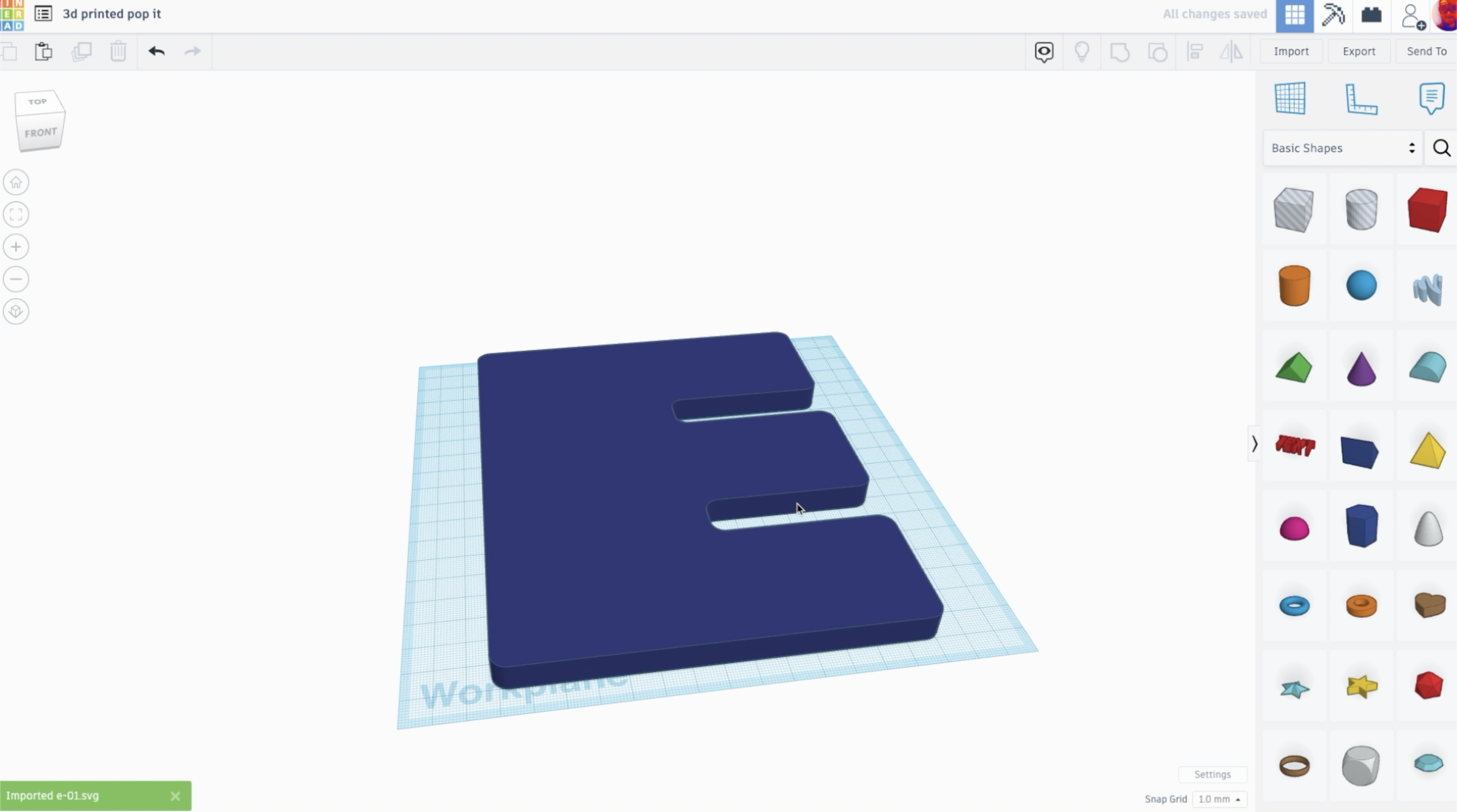
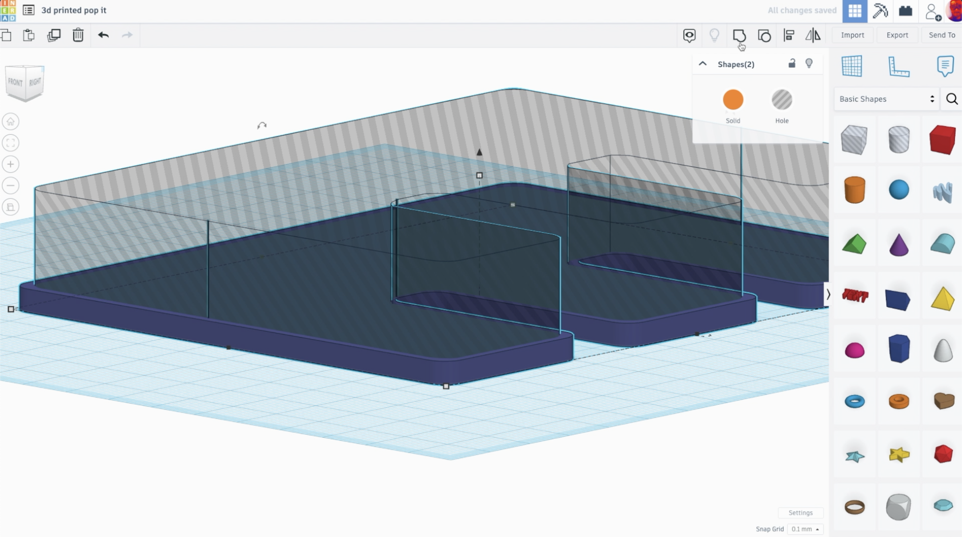
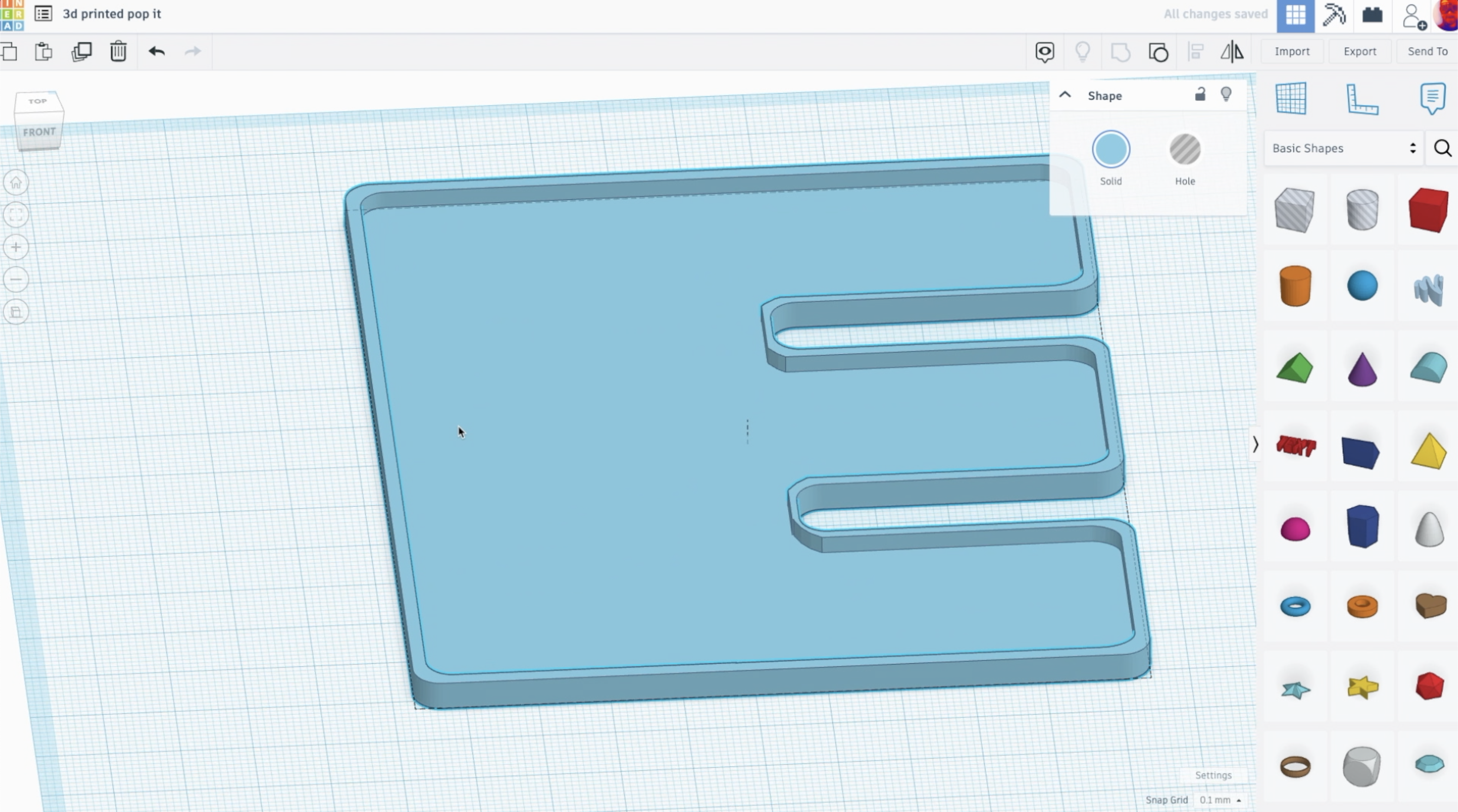
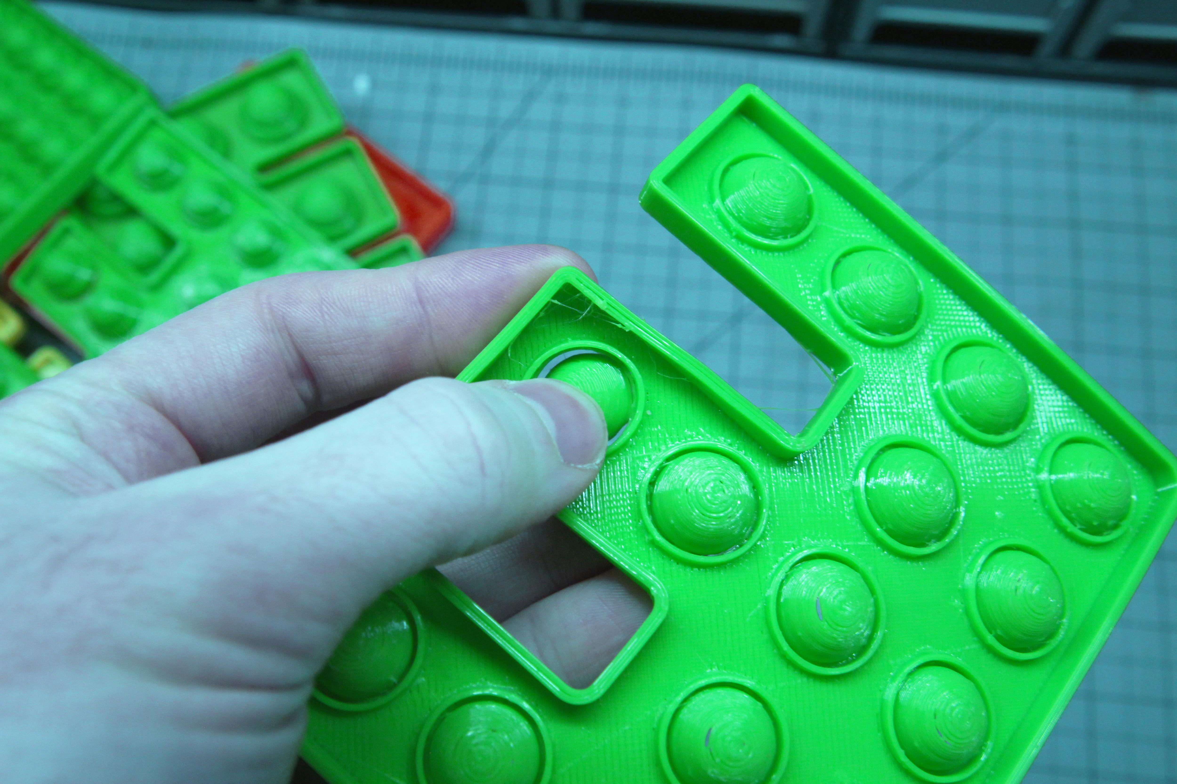
After choosing a CAD program, we need to start to make our pop it! The first step is to create your base shape. This could be anything that offers enough room to create the pop its. For my design, I chose to create an 'E' pop it design and I decided to draw my own custom E rather than using pre-existing fonts in my CAD programs.
Tinkercad has lots of great shapes to choose from, but you can also import vector designs in a .svg file format. To create your own custom vector images, I recommend you use vectr for a free and easy to use program. Adobe Illustrator is a far more professional and industry standard alternative.
After choosing your shape, we need to create a border that will add some rigidity to your pop it. To do this, I duplicated my base shape and scaled it down to fit inside of the outer shape. Because I was working with a slightly complex shape, I actually broke it into smaller pieces so I could scale it down and fit it within using sections rather than one big piece.
Once I had the inner and outer shapes, I set my first important dimensions. The overall size of my pop it was about 5" x 4", or 127mm x 101mm. The thickness of the base was 1.5mm, which is 3 times the thickness of my first layer in my extrusion slice settings. And the height of my outer wall is 1.5mm wide and 4mm tall. The size of the pop it doesn't really matter as long as its big enough to hold the pops without them being too close together (or else they may rip easily). The thickness of the base does matter. I found that if I made the floor of the pop it too thin, it would just rip after a few pops. Keeping the floor thickness proportional to my layer extrusions (3x) offered more consistent and stronger prints.
The wall size is less important, but I keep proportional to my nozzle diameter. I am printing with a 0.5mm nozzle, so my wall width of 1.5mm is 3x the nozzle diameter. This essentially means that my extruder will outline the wall three times to create the wall, which I found to be a good dimension for strength and consistency.
Making the Rings
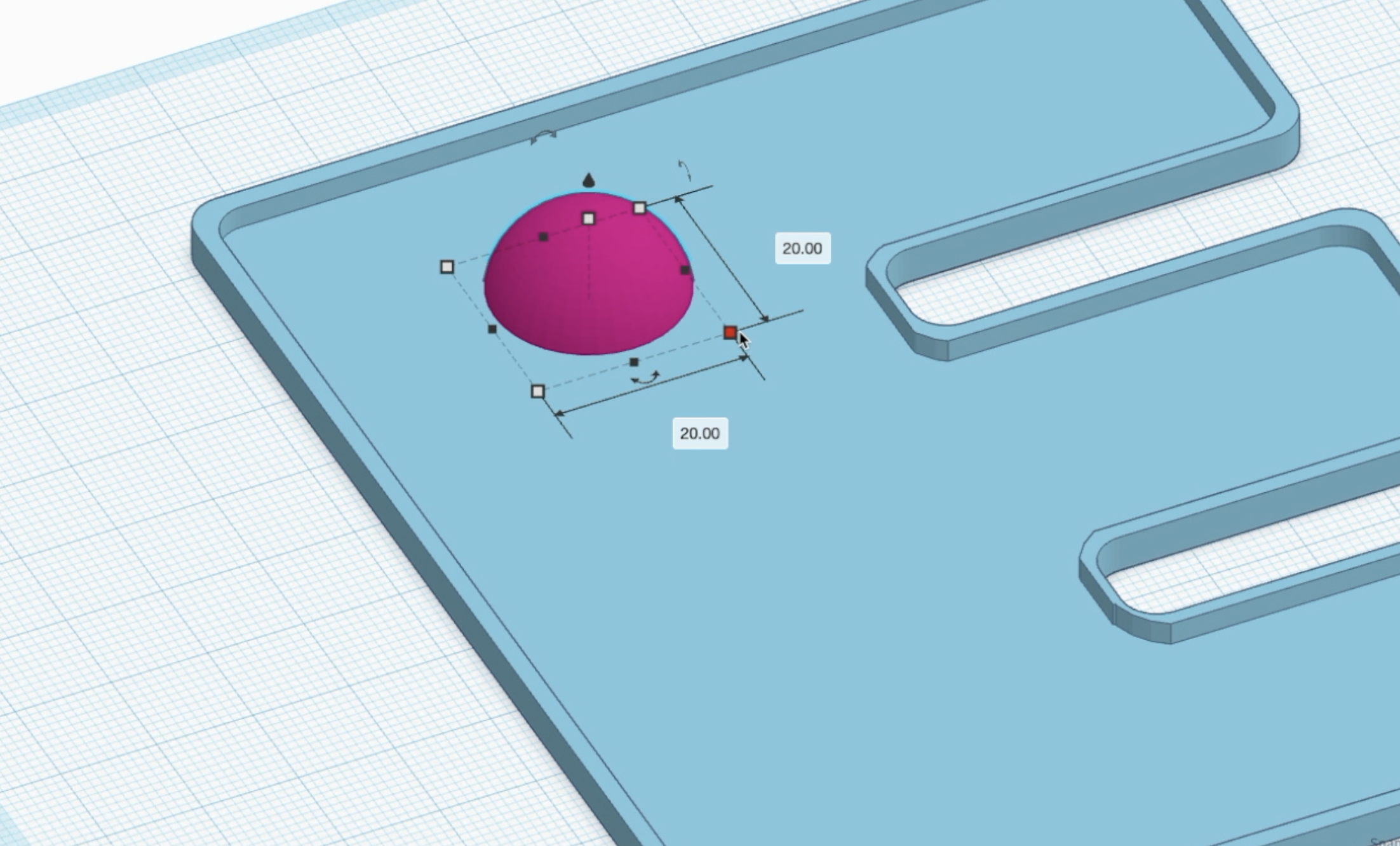
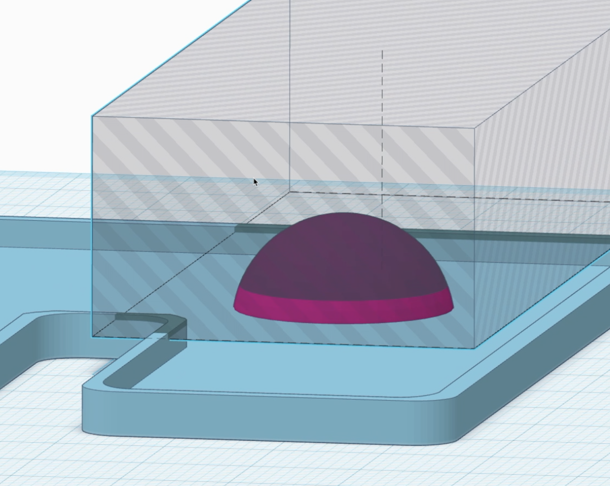
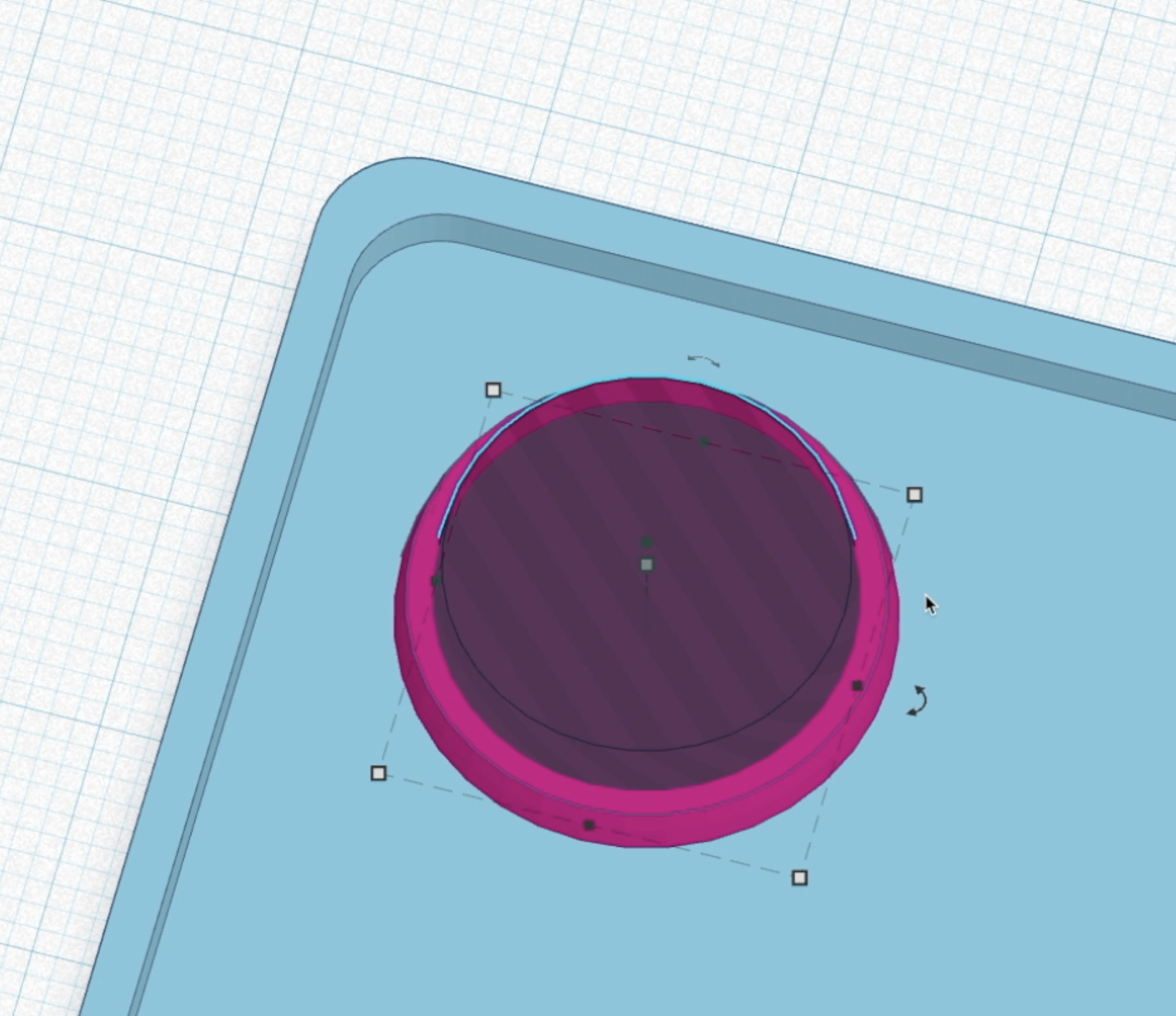
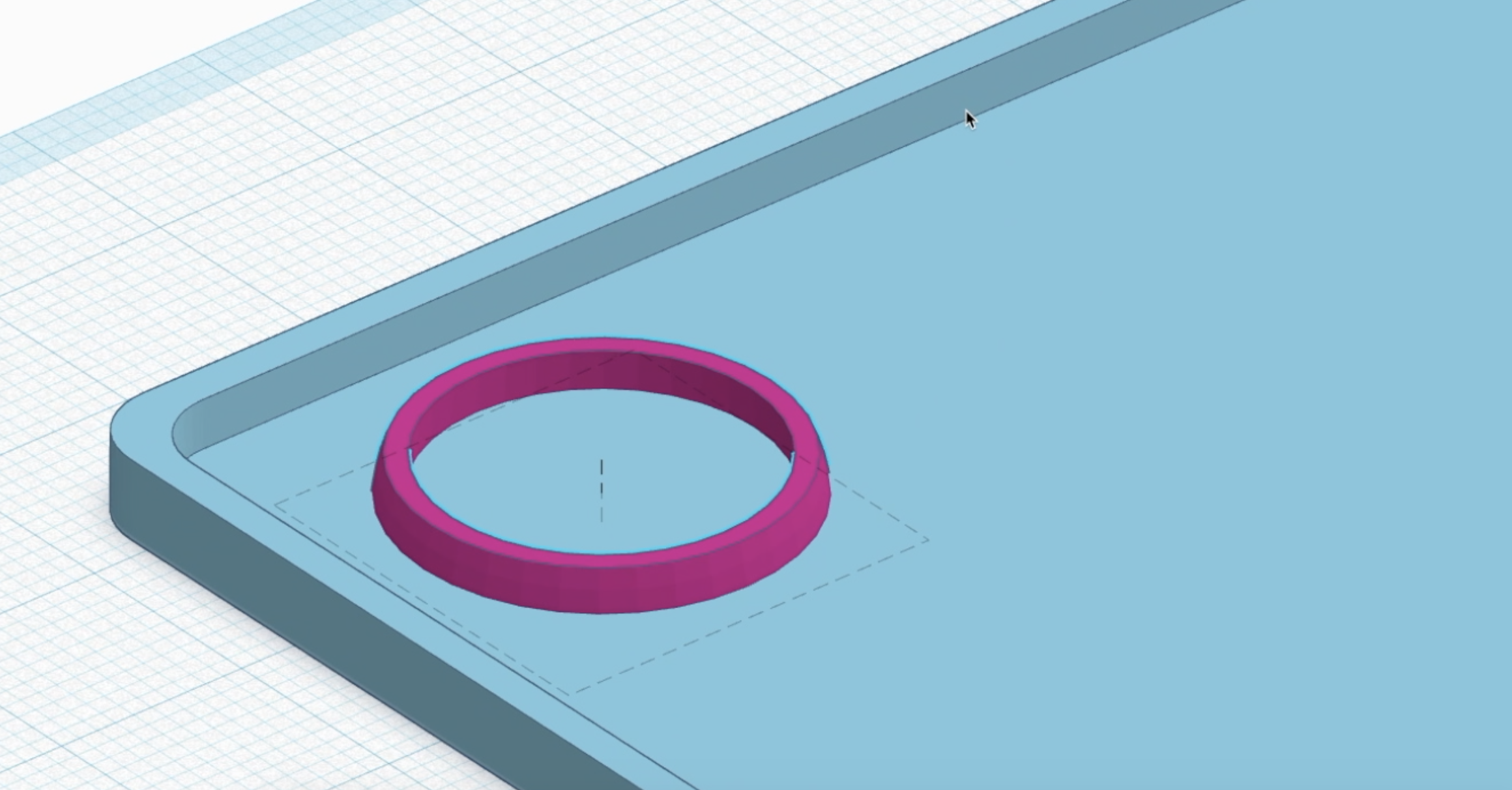
The next step is to create the rings that will reinforce the pop its. This was something I did a lot experimenting with until I found success. The ring doesn't connect with the pop it until it is popped in, then it acts as an extension and reinforcement that creates the satisfying 'pop'.
To create the rings, I made a half sphere that was 20mm x 20mm x 10mm (LWH). I then cut this so it was only 3.5 mm tall by removing the upper curve and leaving just a tapered cylinder. Next, I duplicated this cylinder and made the copy smaller so it was 18mm x 18mm x 10 mm (LWH) and centered within the outer shape. After grouping these two shapes together, I had my first supporting ring.
Making the Pops
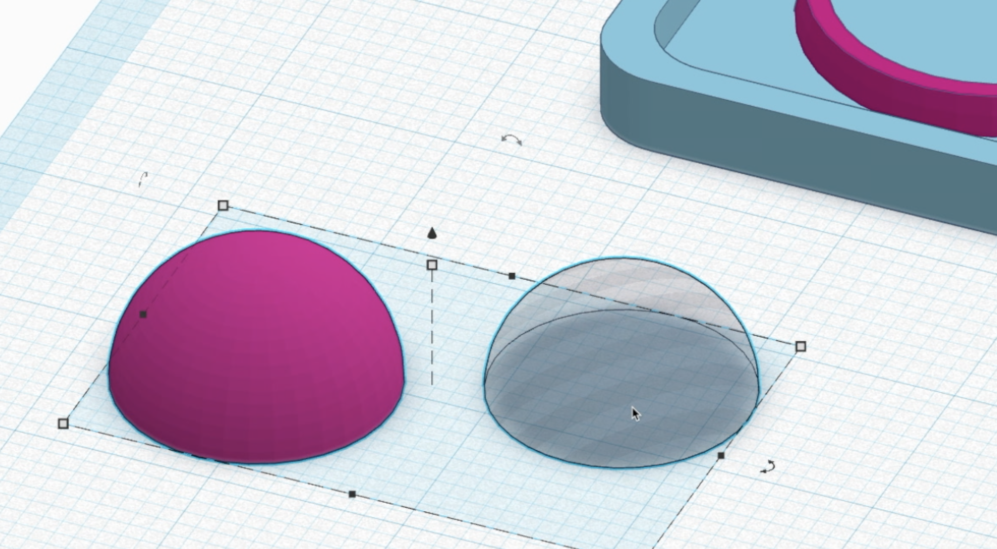
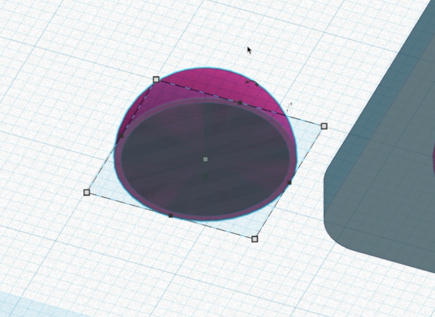
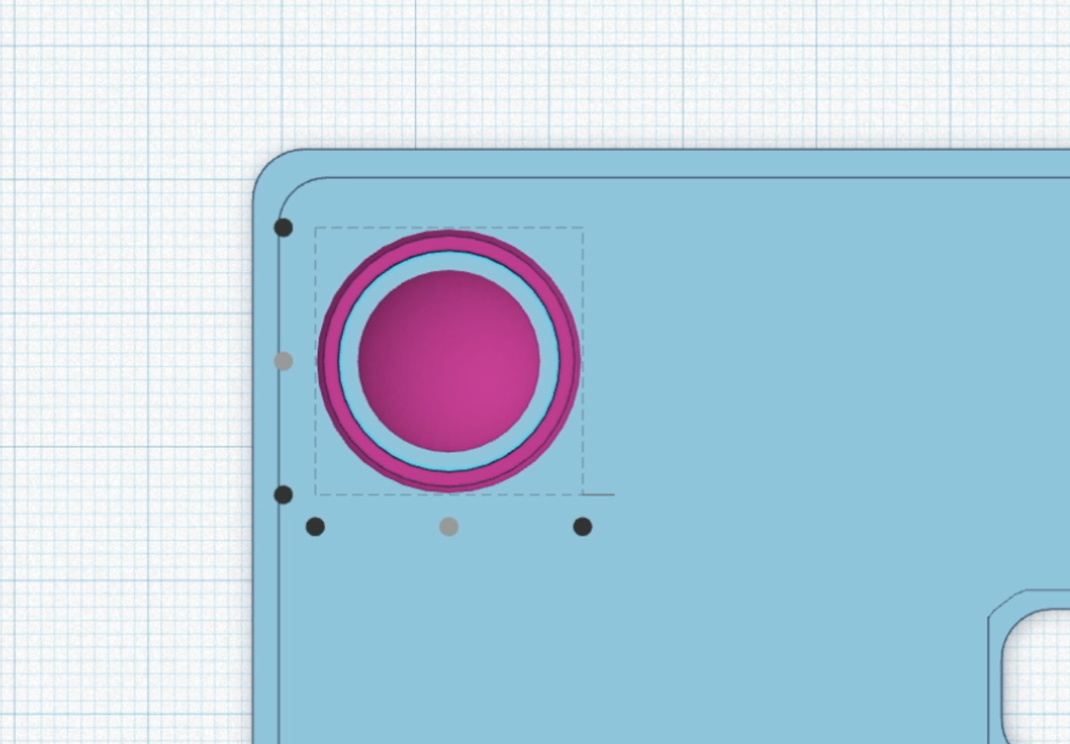

Now time to create the pops! Starting with a half sphere, I dimensioned it to be 14mm x 14mm x 7mm (LWH). This would leave a 2mm gap between the walls of the pop bubble and the supporting ring which I found to be a good measurement for my 0.5mm nozzle.
Next, I duplicated this half sphere and set it to be exactly 1mm smaller all the way around (13mm x 13mm x 6mm). I then set it to be a hole shape and centered it within the outer half sphere of the pop. I didn't group these together yet as that will come in a later step, but when grouped this will give use a pop wall thickness of 1 mm.
I think this is probably the most important dimension. When printing with a thinner wall thickness, I found stringy or inconsistent prints, or pops that would rip easily. I also believe this measurement should be proportional to your nozzle diameter. For my 0.5mm nozzle, I doubled its width to create the wall thickness of 1mm for each pop.
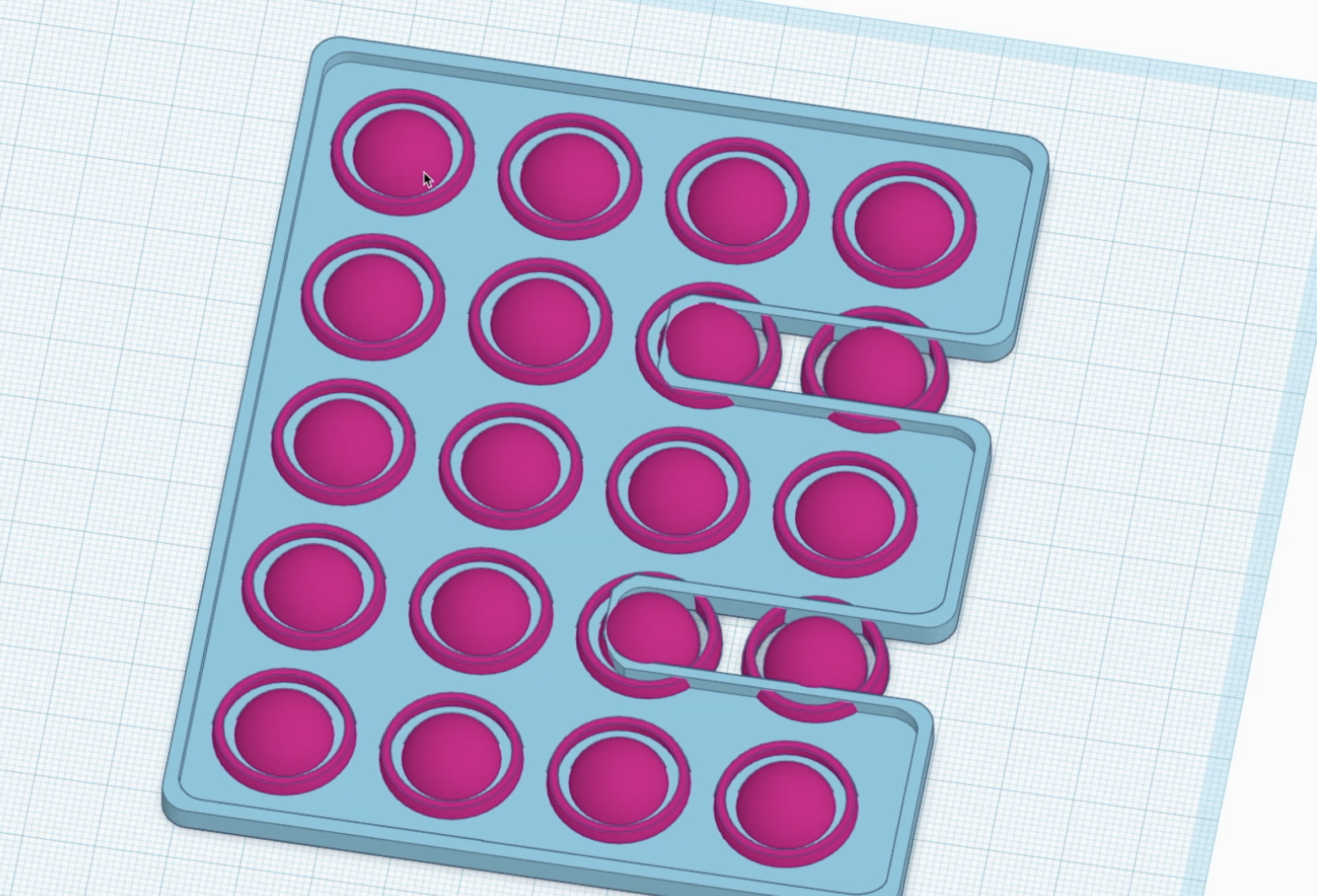
Lastly, I centered the pop spheres and the outer ring, then patterned them across my shape. In my 5"x4" 'E', I could fit four columns and 5 rows, or one pop per square inch. I used Tinkercad's duplicate tool to pattern evenly, then went and deleted extra pops in sections of my base that were cut out.
Finalizing the Shape
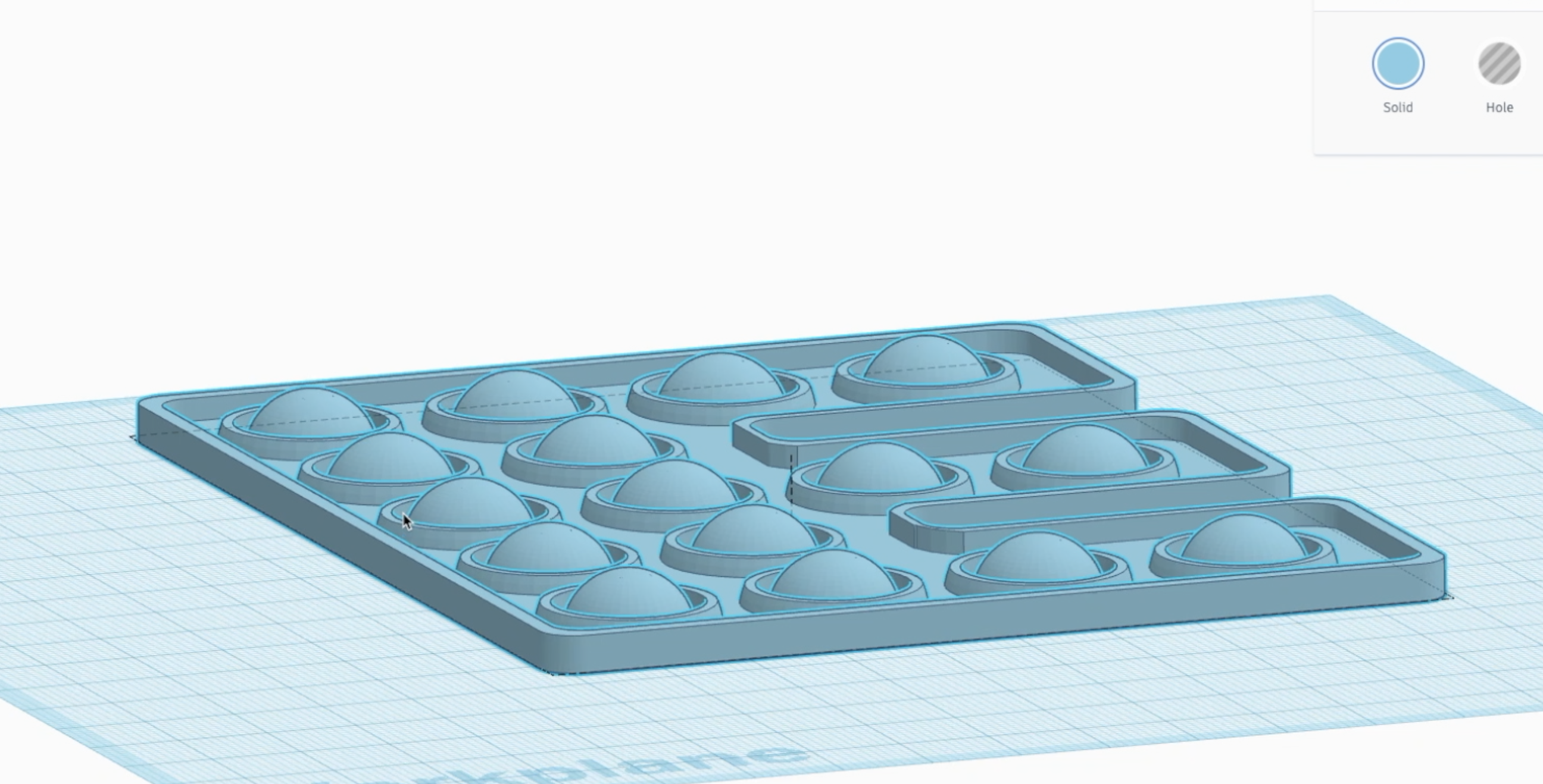
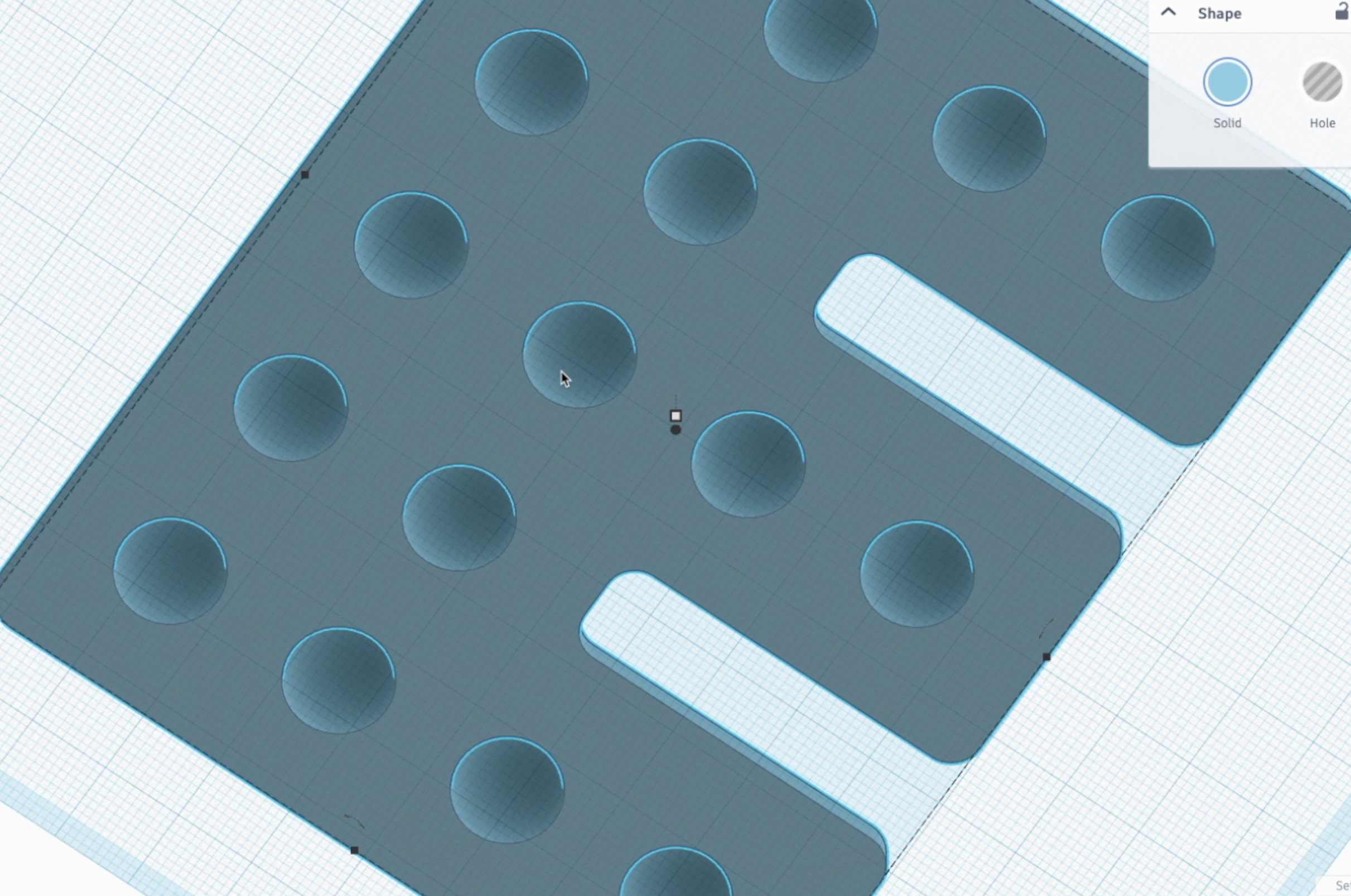
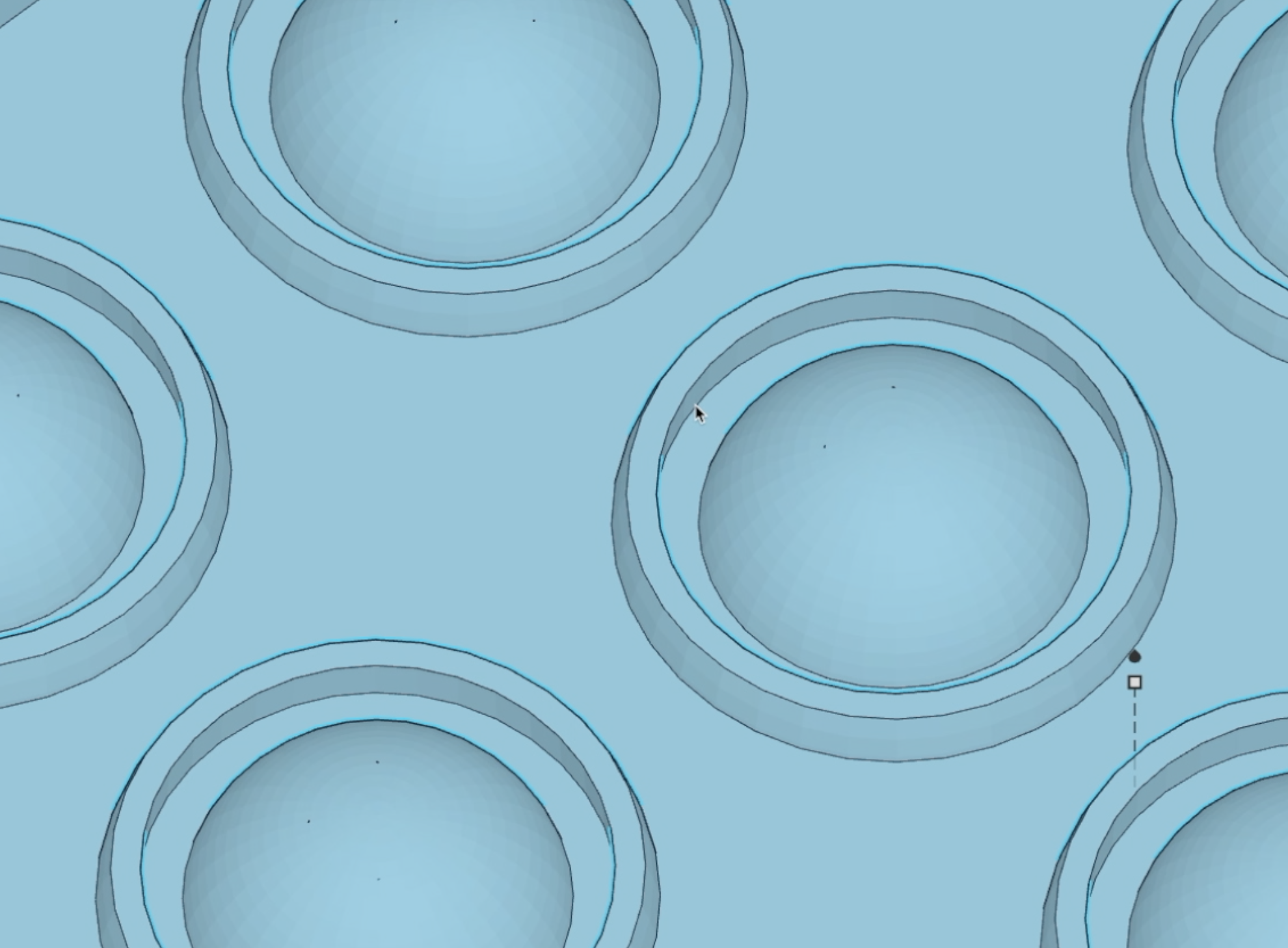
The last step in creating the pop when using Tinkercad is to group it all together! Because we kept the hole half sphere's ungrouped, the pops where hollowed out and holes were cut through the base all at the same time. The end result should be one solid part with our half spheres nested inside of the outer rings.
Once the design is done, all that's left is to export it as a STL file and send it to your slicer!
Preparing the Print
Prior to finding success in this project, I experimented with a lot of different flexible TPU and TPE filaments. In addition to NinjaFlex 85a which is the one that worked the best, I tried PolyFlex 95 and 90 by PolyMaker, GizmoDorks TPU (which in general is my favorite to use), and SainSmart TPU. SainSmart was the most rigid by far, and PolyFlex 90 was closer to success but ripped consistently. The NinjaFlex is the most expensive, but offered the best result time and time again.
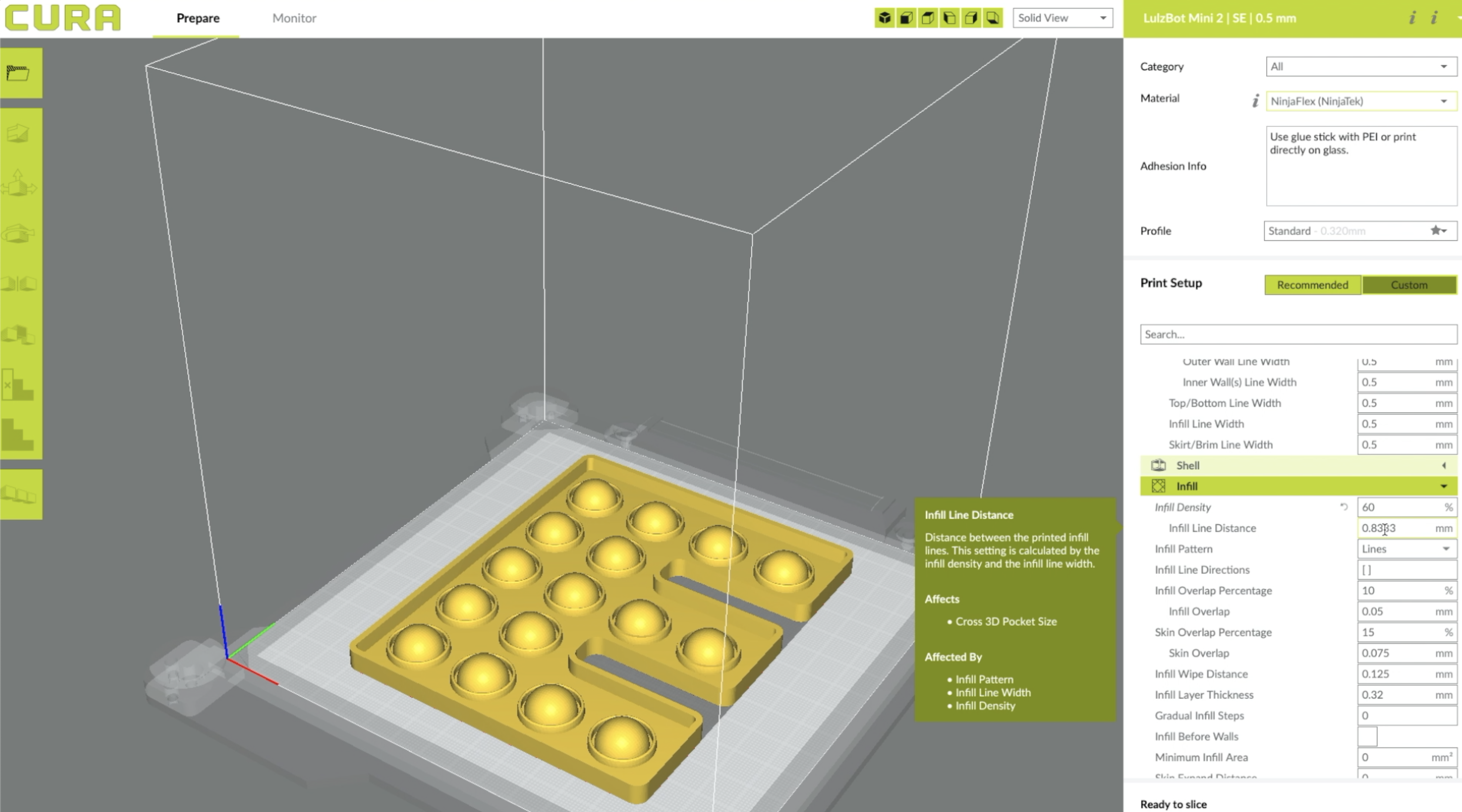
For my LulzBot 3D printers, I prepare my prints in the Cura LulzBot Edition slicer program. Like the original Cura, Cura LE works with a lot of different printers and acts as a pretty powerful slicer with a ton of tools to customize and tune your prints.The majority of success for this project comes from the design though, so slicing is pretty straight forward! I used the following settings:
- NinjaFlex Filament
- 0.32mm layer height
- 0.5mm nozzle width
- 0.5mm initial layer height
- 60% infill density
- 0.83mm line width
- line infill pattern
- 225 c nozzle temp (default)
- 60 c bed temp (default)
- No special bed adhesion
- No supports
One thing I like to do is to print a skirt 3 or 4 times. The skirt doesn't actually touch the print, but outlines it before starting the model. This allows me to ensure the model is in the correct location on the print bed, and also that my z height offset is optimized before the first layer begins.
Printing
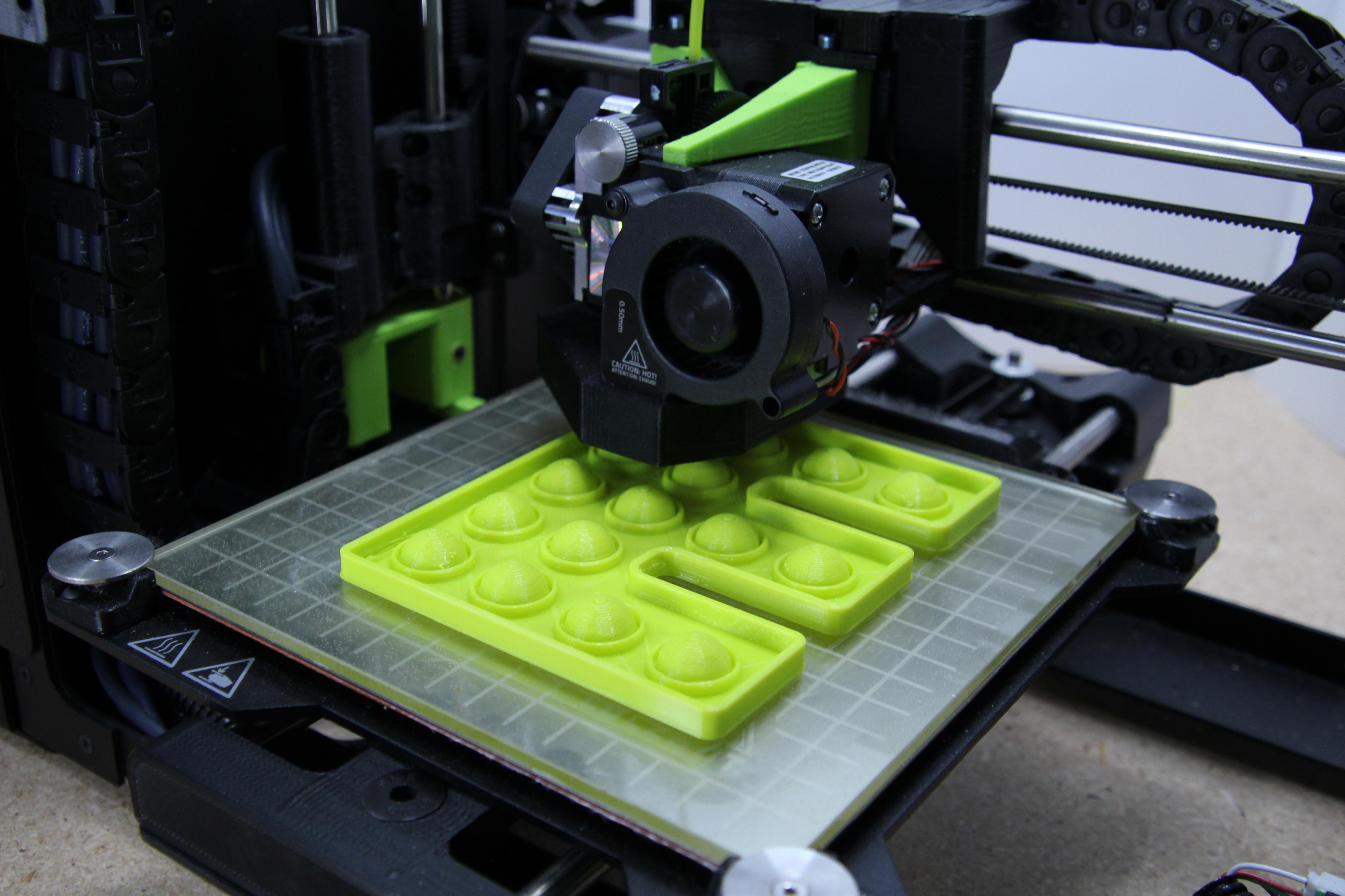
Once your Gcode is prepared, its time to print! LulzBot 3D printers can print flexible filament right out of the box, so I didn't need to modify or adjust my print head prior to printing. I did flip my glass bed over so I printed directly onto glass rather than PEI. I also used a glue stick to add a bit more adhesion for the flexible filament onto the glass surface.
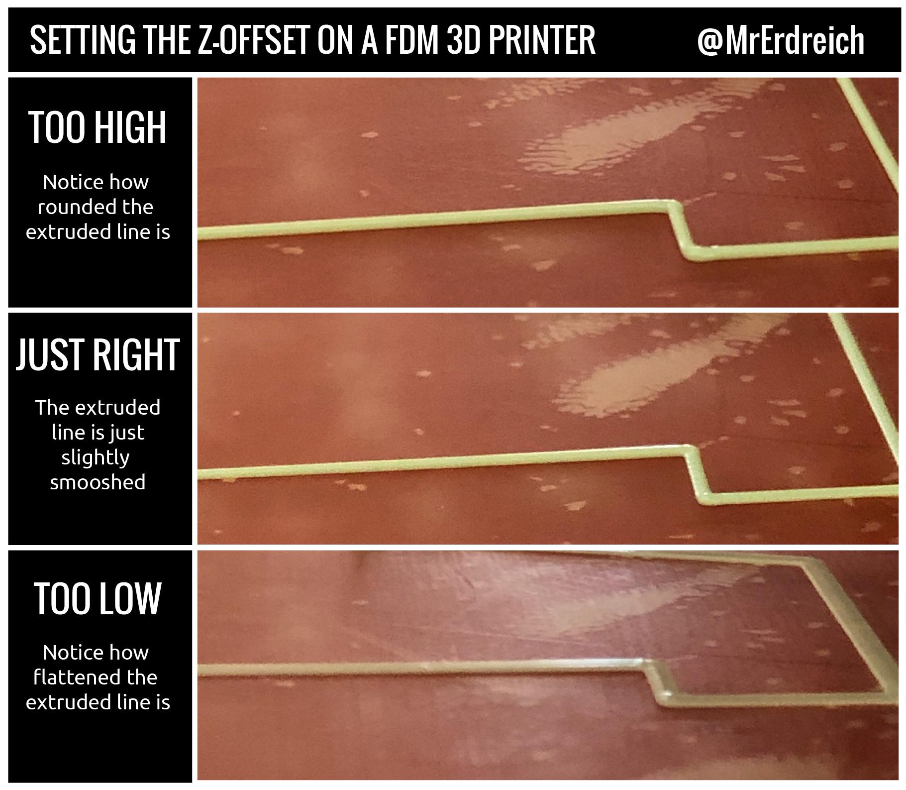
As mentioned in the previous step, the first layer is the most important step towards a successful print. Using the skirt, I rub my finger across the print (carefully) to ensure there is good adhesion, then adjust the z height offset to tune as needed. LulzBot's do auto calibrate every print, so this is usually pretty close to accurate. But I find that changing the filament, flipping the bed over, or putting down glue can throw this off a bit so its good to check every time. See the attached image for identifying optimal z height for your first layer.
Popping
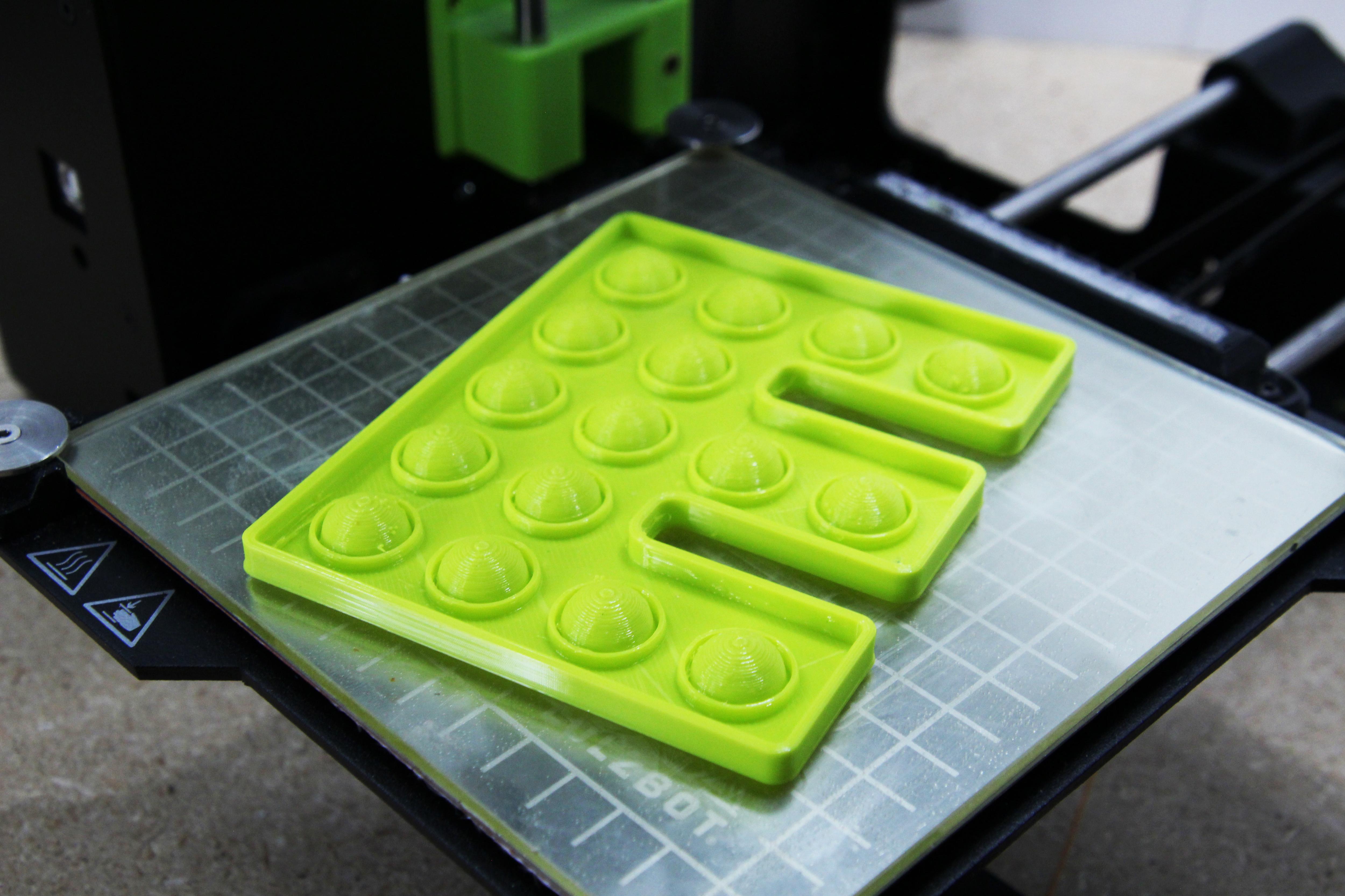
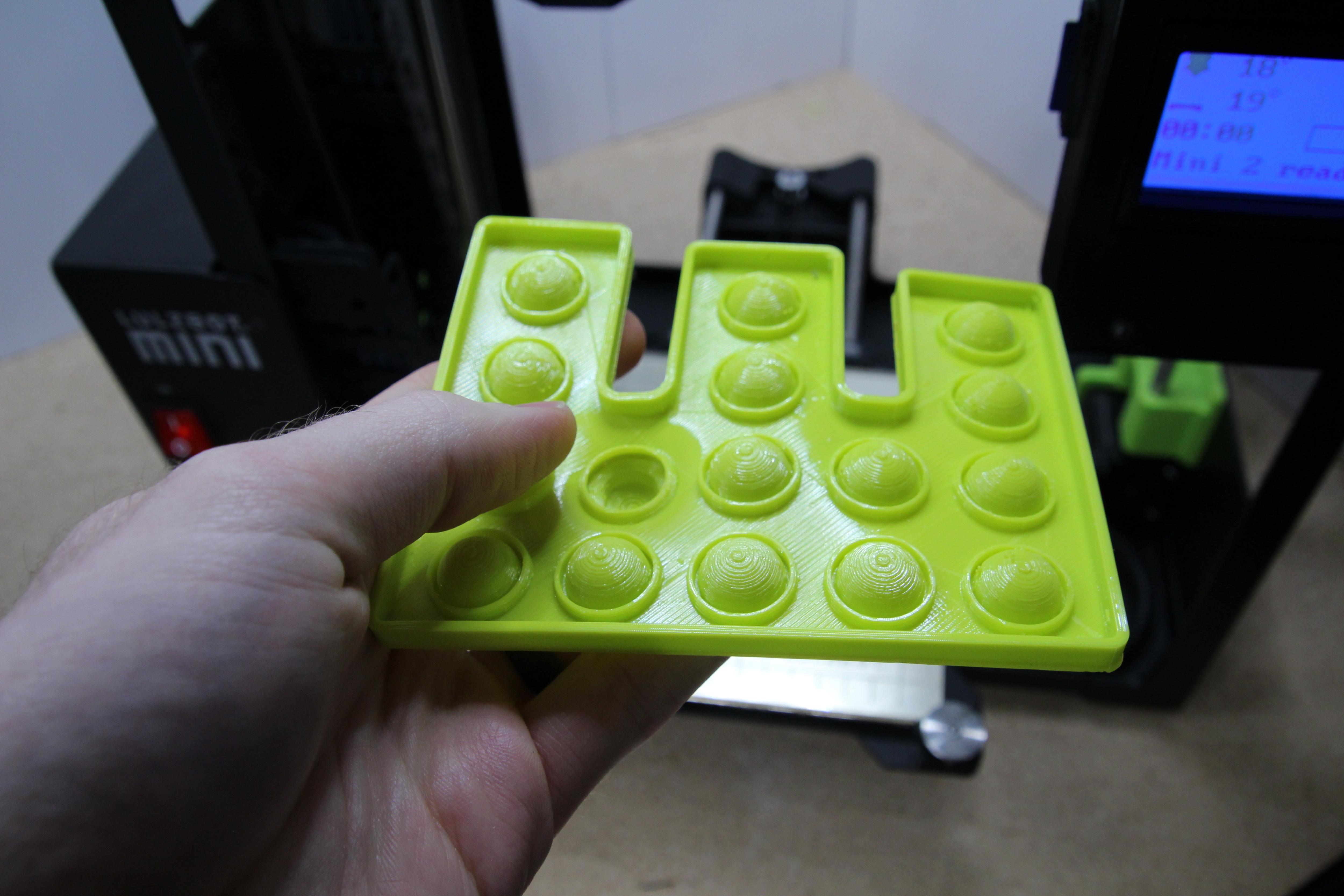
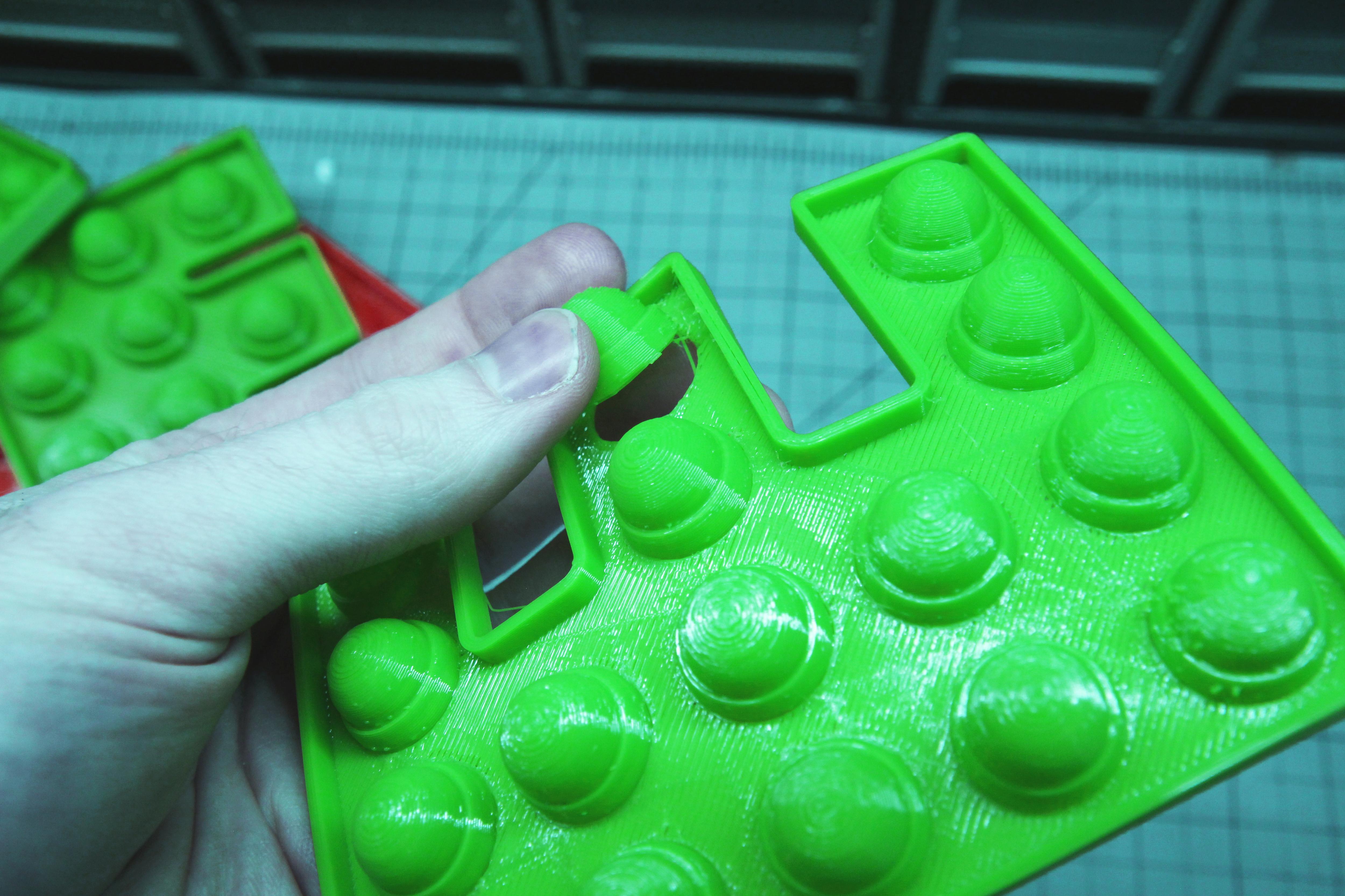
Once printed, its time to peel the part off the bed and pop away! So the question is, are 3D printed Pop Its as poppy as an off the shelf product? No.
When I attempted to reduce the tolerances so the prints were as thin as the molded off the shelf product, I was faced with failed prints or ripping prototypes....even when I printed with a smaller 0.25mm nozzle. But I am still happy with the outcome of this project. While these 3D printed models are a bit more firm and require a bit more effort to push in, the pop is still a very satisfying and audible "pop". And the overall part is super flexible, crumples, squishes, and folds just like the real deal.
In conclusion, I am super pleased with this project! I think its another awesome use for the capabilities of 3D printers and offers a good combination of customizability, consistent printing, and usability that makes a solid project. I hope you enjoyed this instructable and attached videos to be useful, as always thanks for reading and happy making!