3D Printed Pocket Watch From "The Pocket Watch Gang"
by 3DPrintingEnthusiast in Workshop > 3D Printing
909 Views, 4 Favorites, 0 Comments
3D Printed Pocket Watch From "The Pocket Watch Gang"
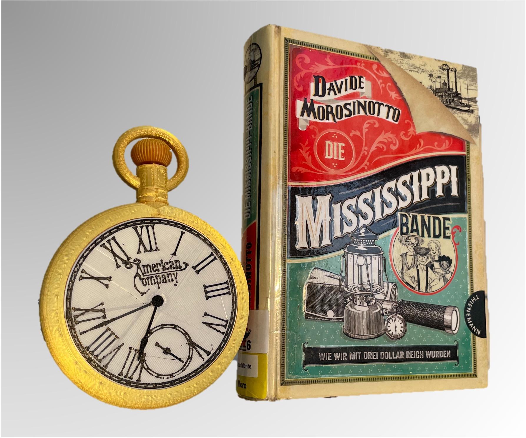
I recently read the book The Pocket Watch Gang and I enjoyed the book a lot. I read it in German (in German it's called Die Mississippi Bande) and it sadly wasn't translated into English even though it takes place in America. I decided to design the broken pocket watch featured in the book because it plays a crucial role in the book.
I'm a 7th Grade student in Germany at the Maria von Linden Gymnasium.
Supplies

- 3D Printer
- The Book : The Pocket Watch Gang
- PLA Filament (in gold, black, and white)
- 1/1.2 mm diameter wire/carbon rods
Look for Pieces of Information in the Book
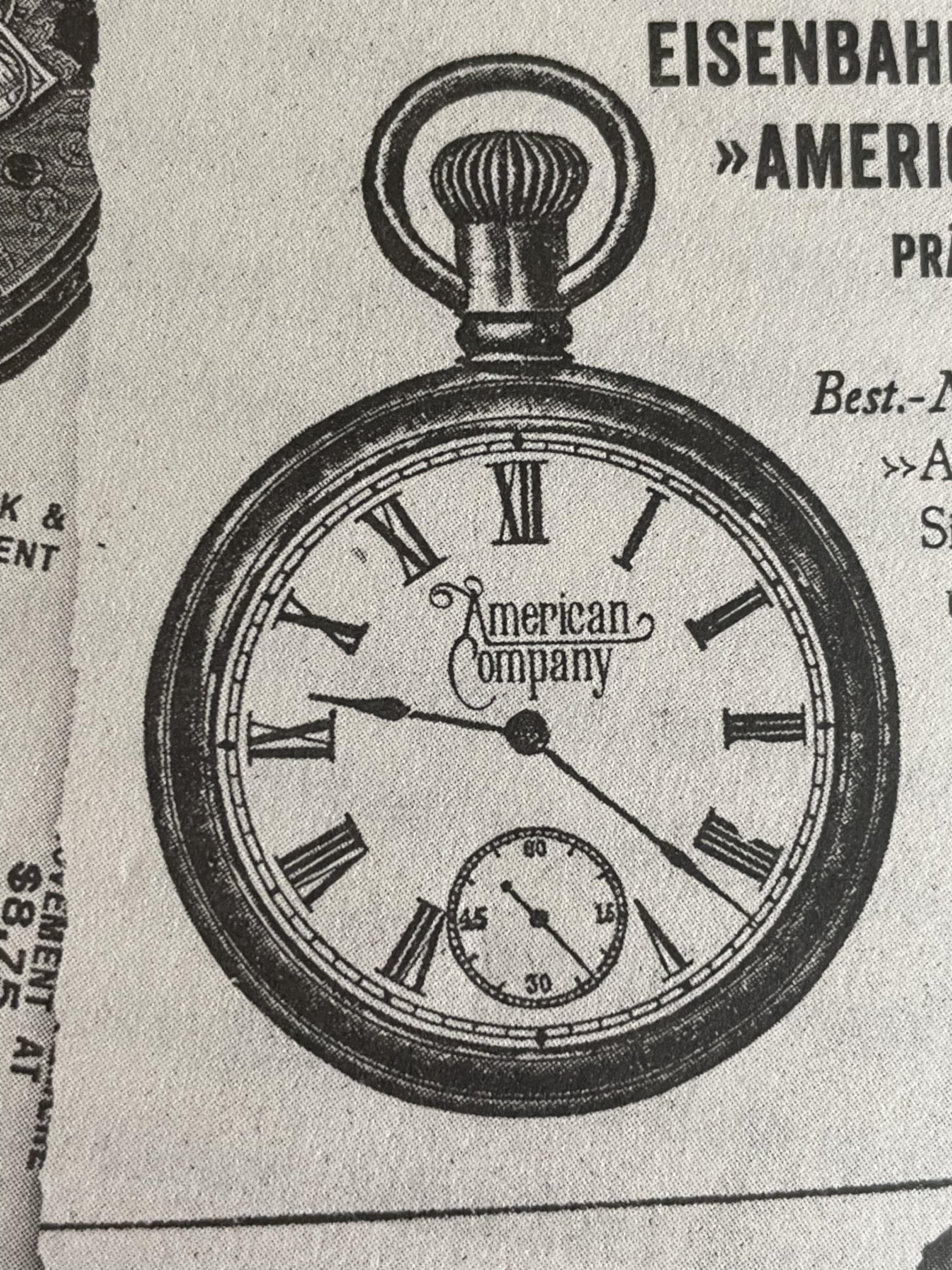
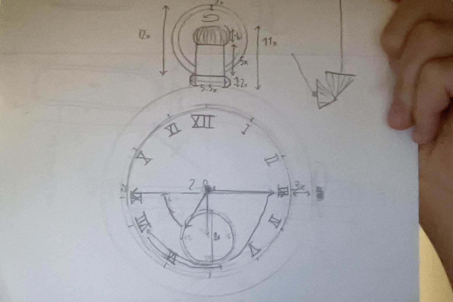
First I scavenged the book for any descriptions or pictures of the watch.
I was lucky and found the picture above.
Next I sketched out my plan for the watch on a piece of paper and added proportions.
Bringing in the Picture Into Fusion 360
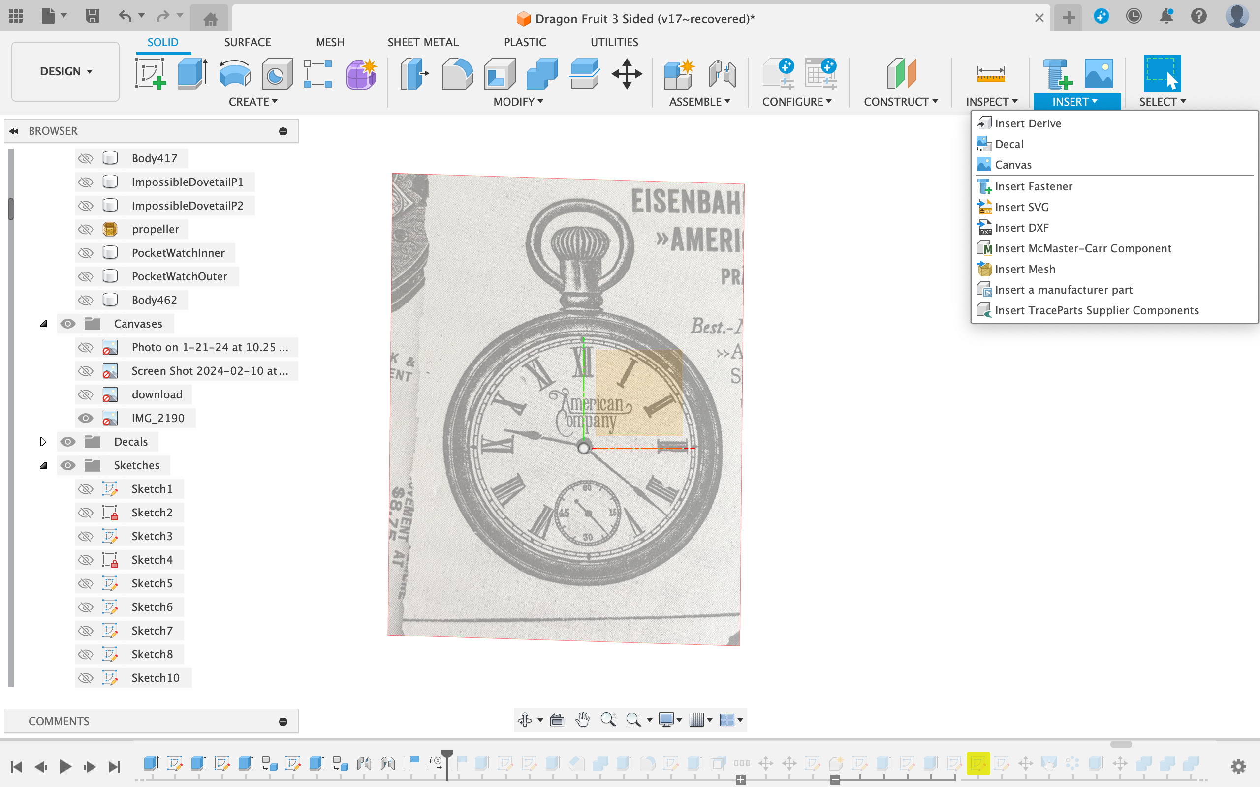
First, created a canvas in Fusion360 of the photo of the watch and scaled it using the calibrate tool.
Designing the Basic Shape
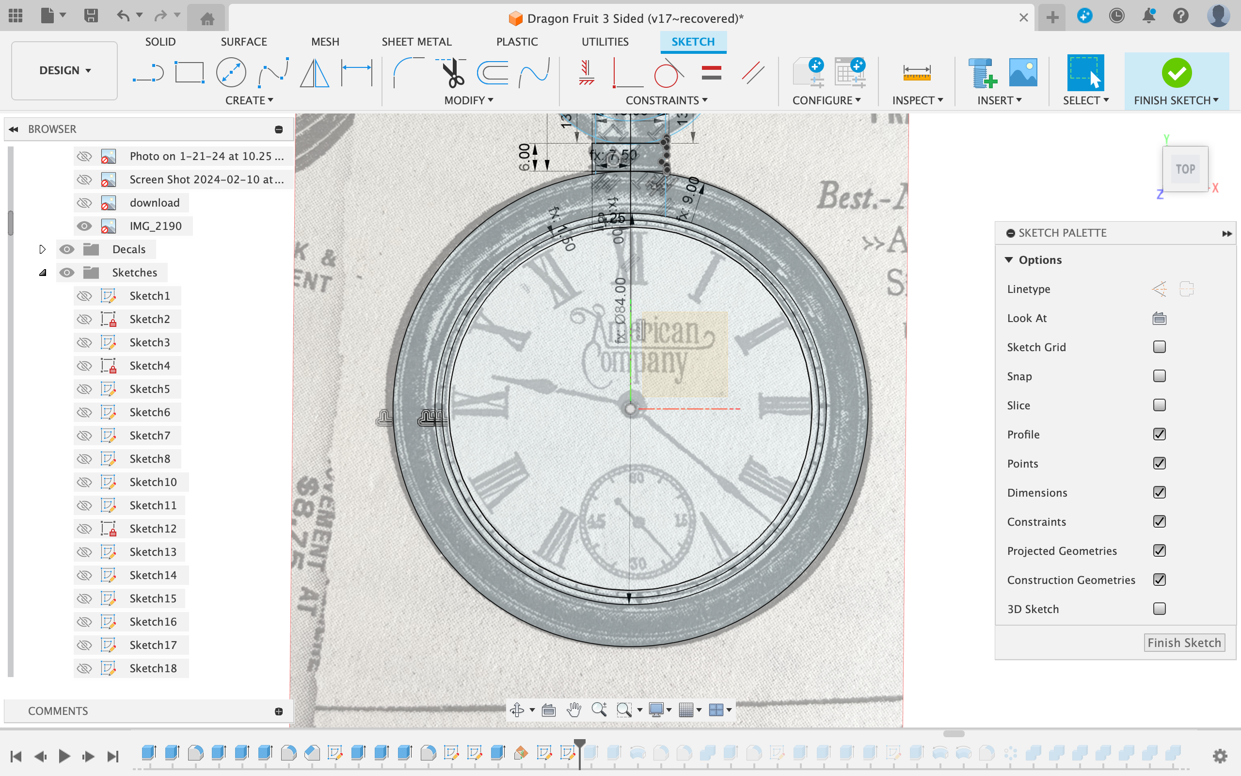
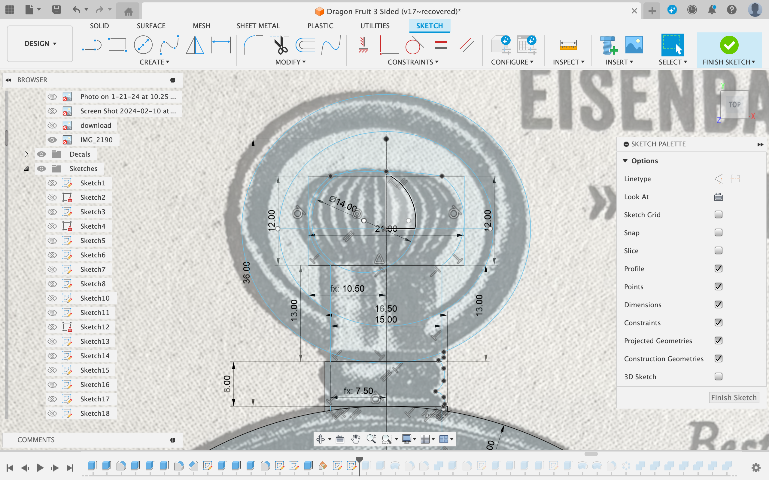
When designing parts in Fusion I always think about how you can decompose the object into basic shapes (cylinders, cubes, prisms, cones, etc)
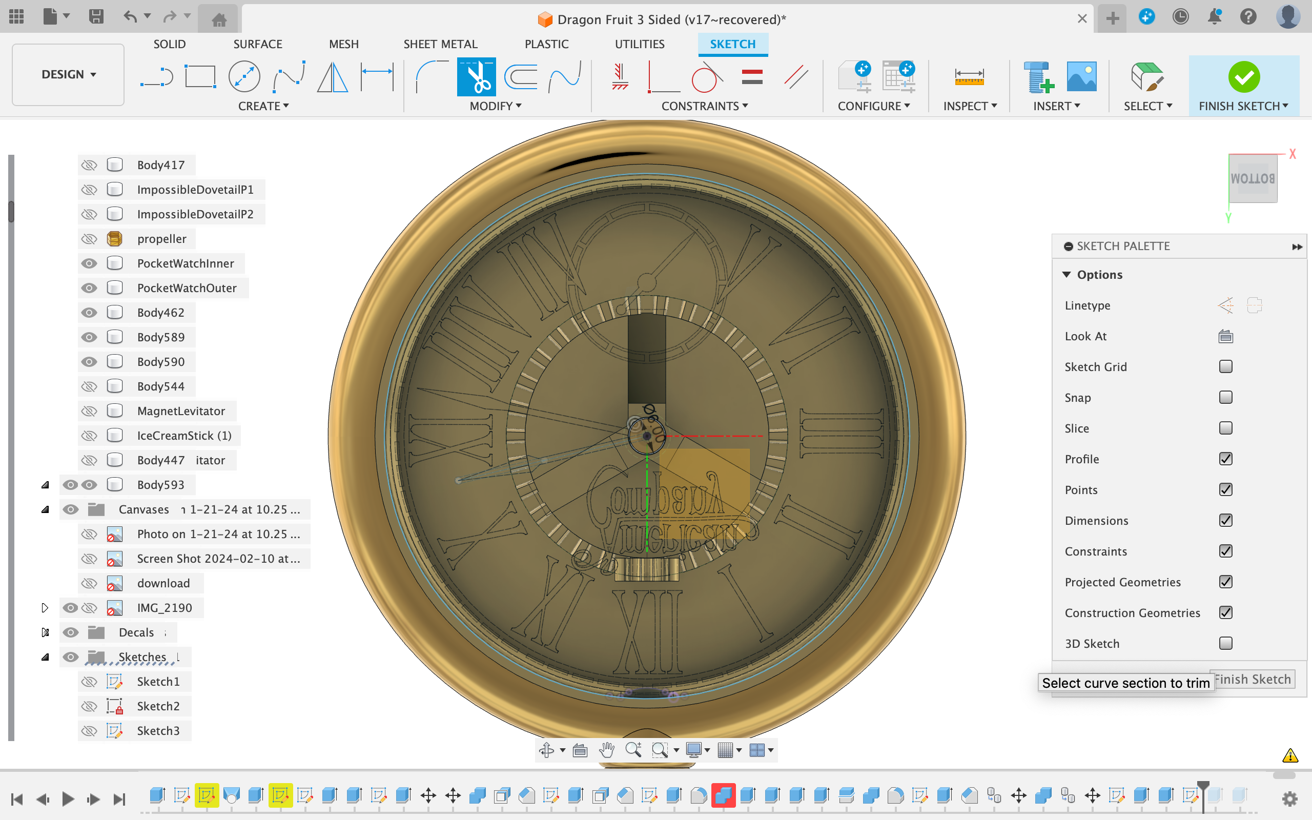
I created a sketch on the xy plane and started by drawing circles as an outline for the watch.
Next I started to sketch out the wind up mechanism using several rectangles.
Then I refined those rectangles to more closely match the actual shape by using splines.
For the ring I used 2 ellipses.
Extruding the Basic Shapes
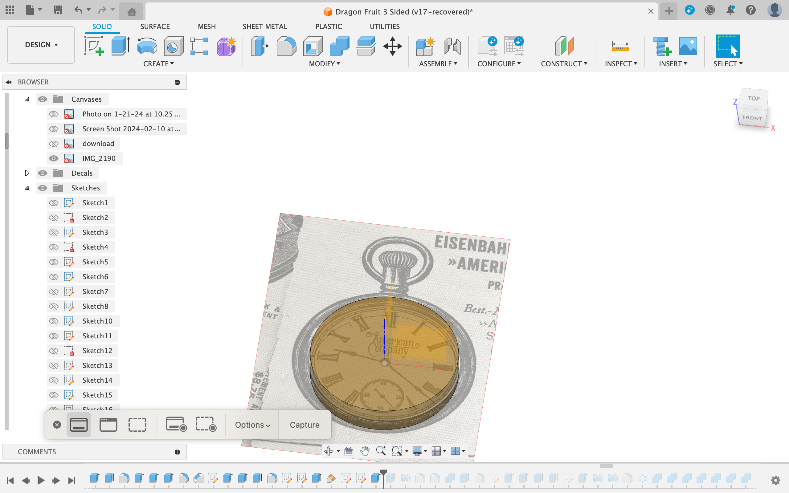
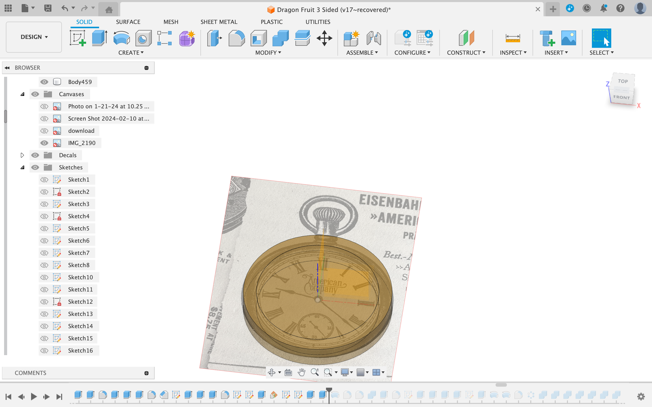
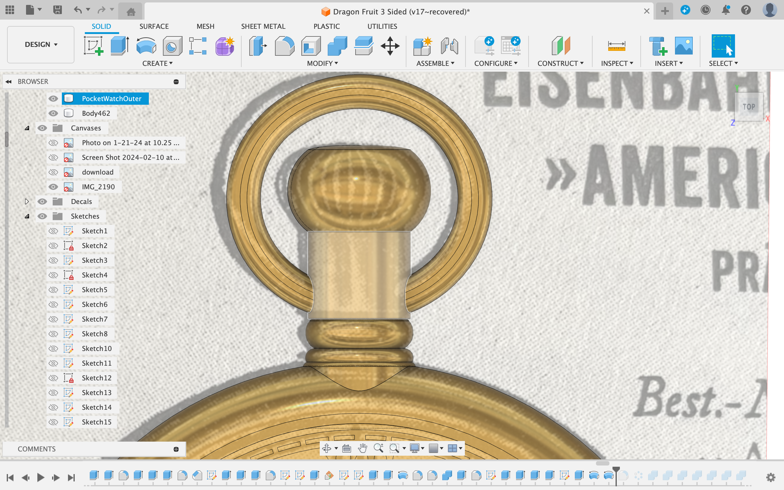
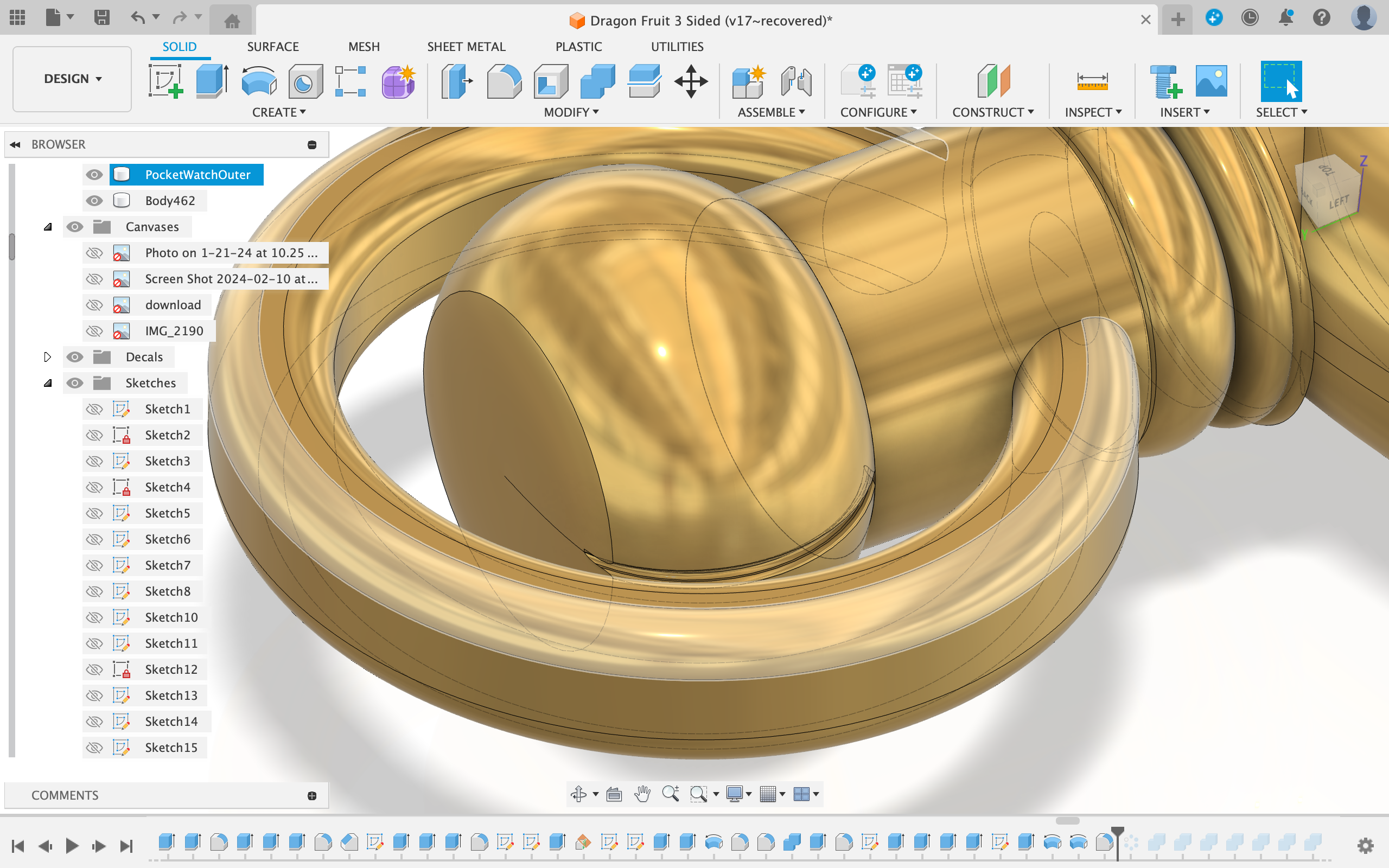
After that I symmetrically-extruded the two main objects (the ring and the circle) making sure to create two separate bodies.
Then I filleted the outer edges of the ring.
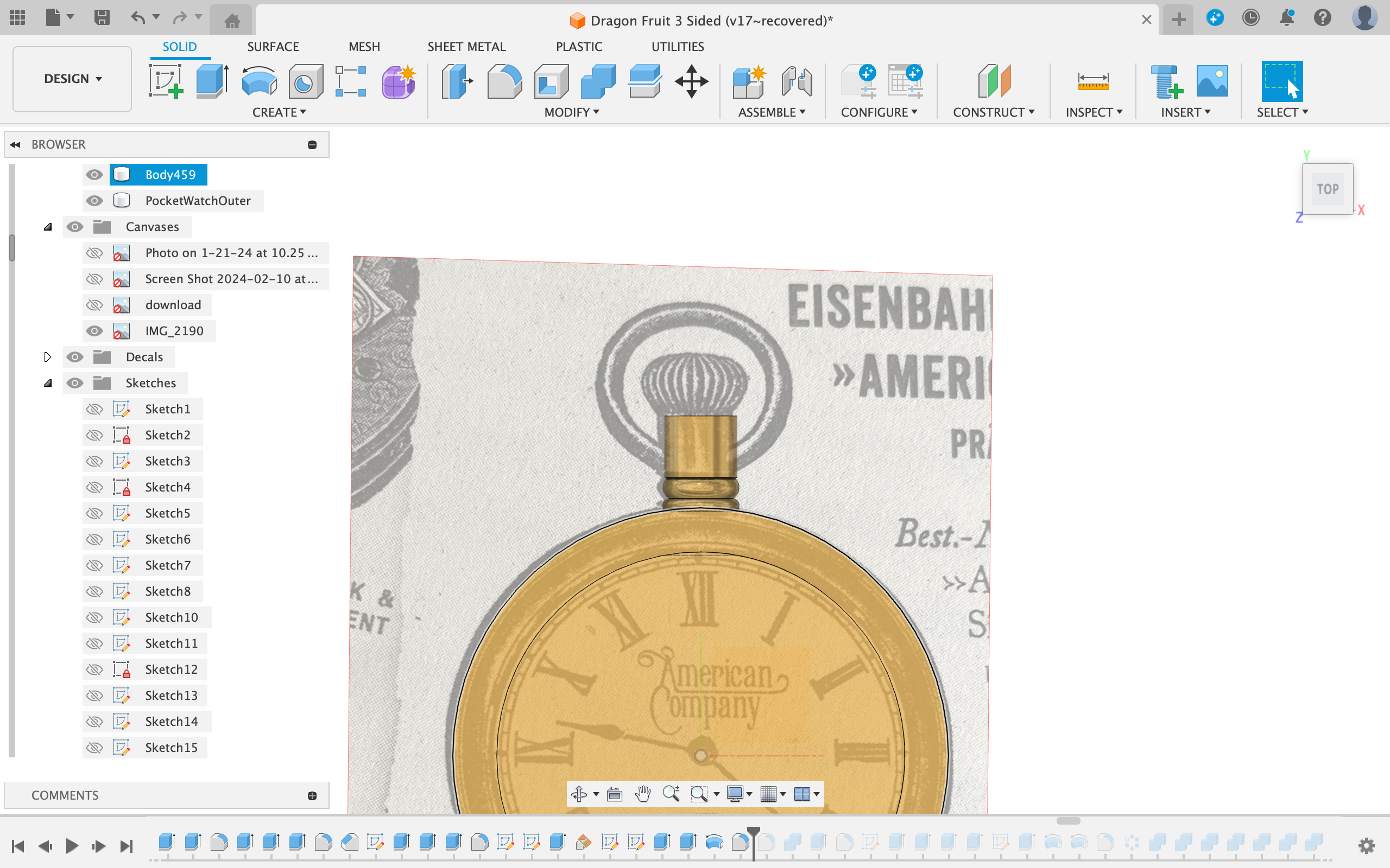
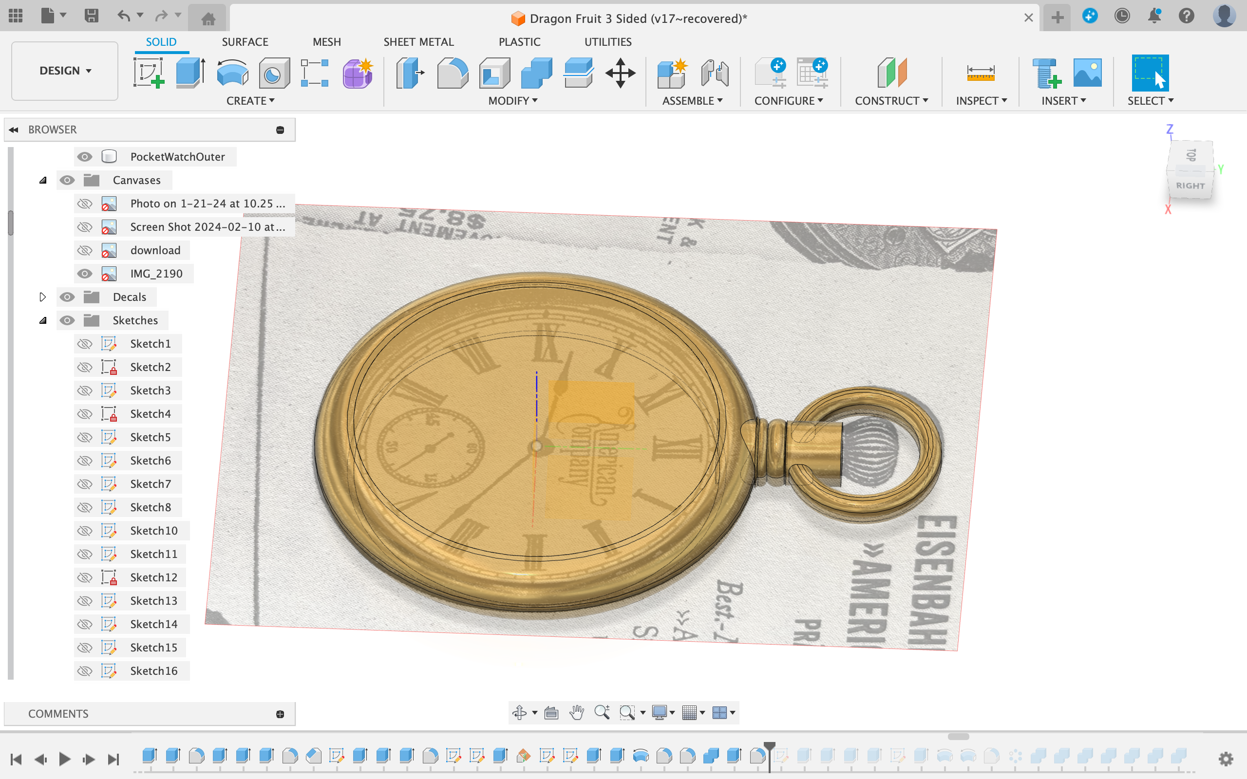
Next I revolved the connecting shaft at the top (view picture) and symmetrically-extruded the smaller ring.
I also filleted the smaller ring to make it round.
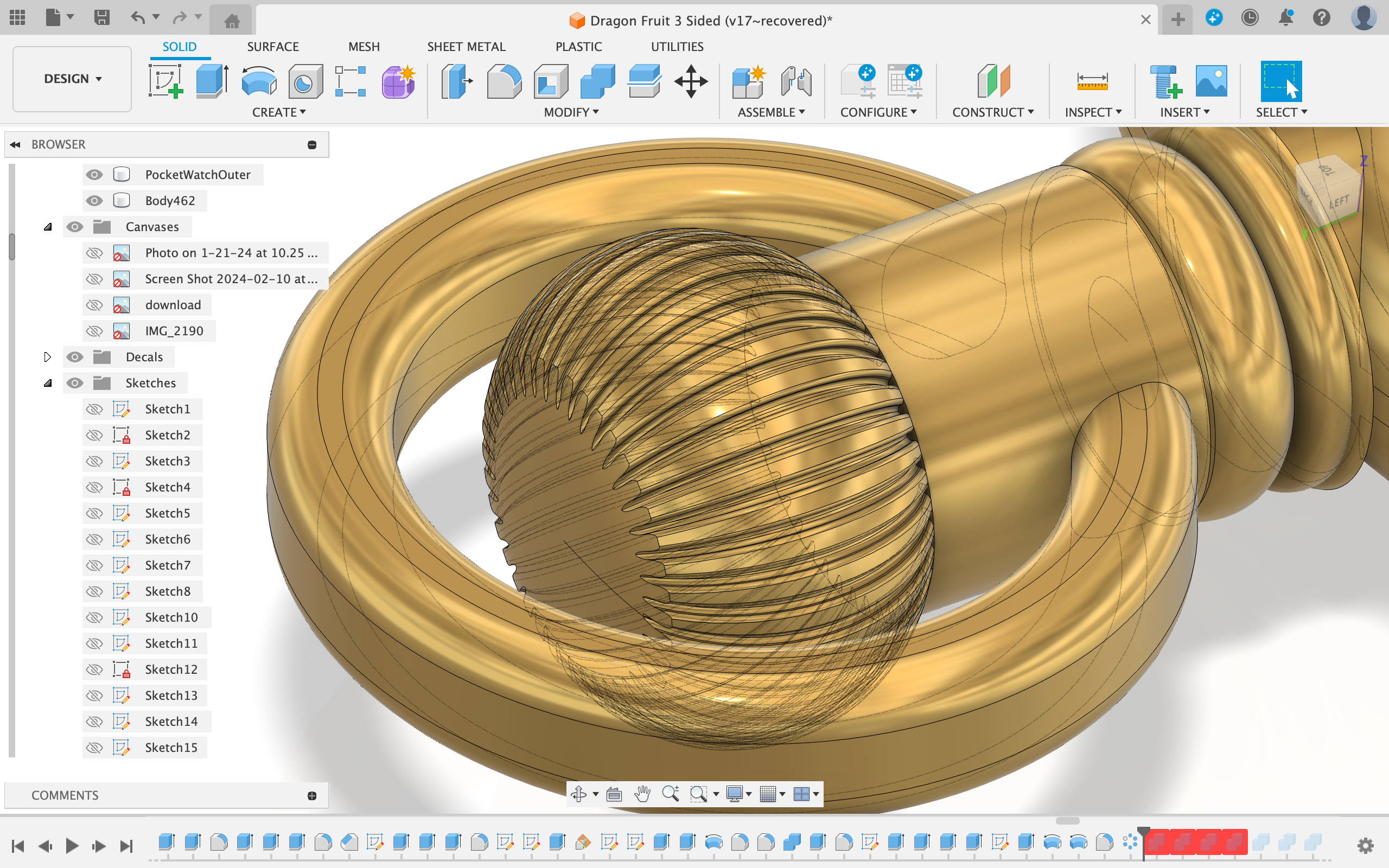
Subsequently I revolved the winding crown and made sure that it was a new body.
I decided to add little groves in the winding crown so I edited the first sketch, created an offset to the rotary part sketch of 1mm and symmetrically-revolved it partially (around 3 degrees).
Then I patterned the feature around the whole rotary-part.
The Text and Roman Numerals
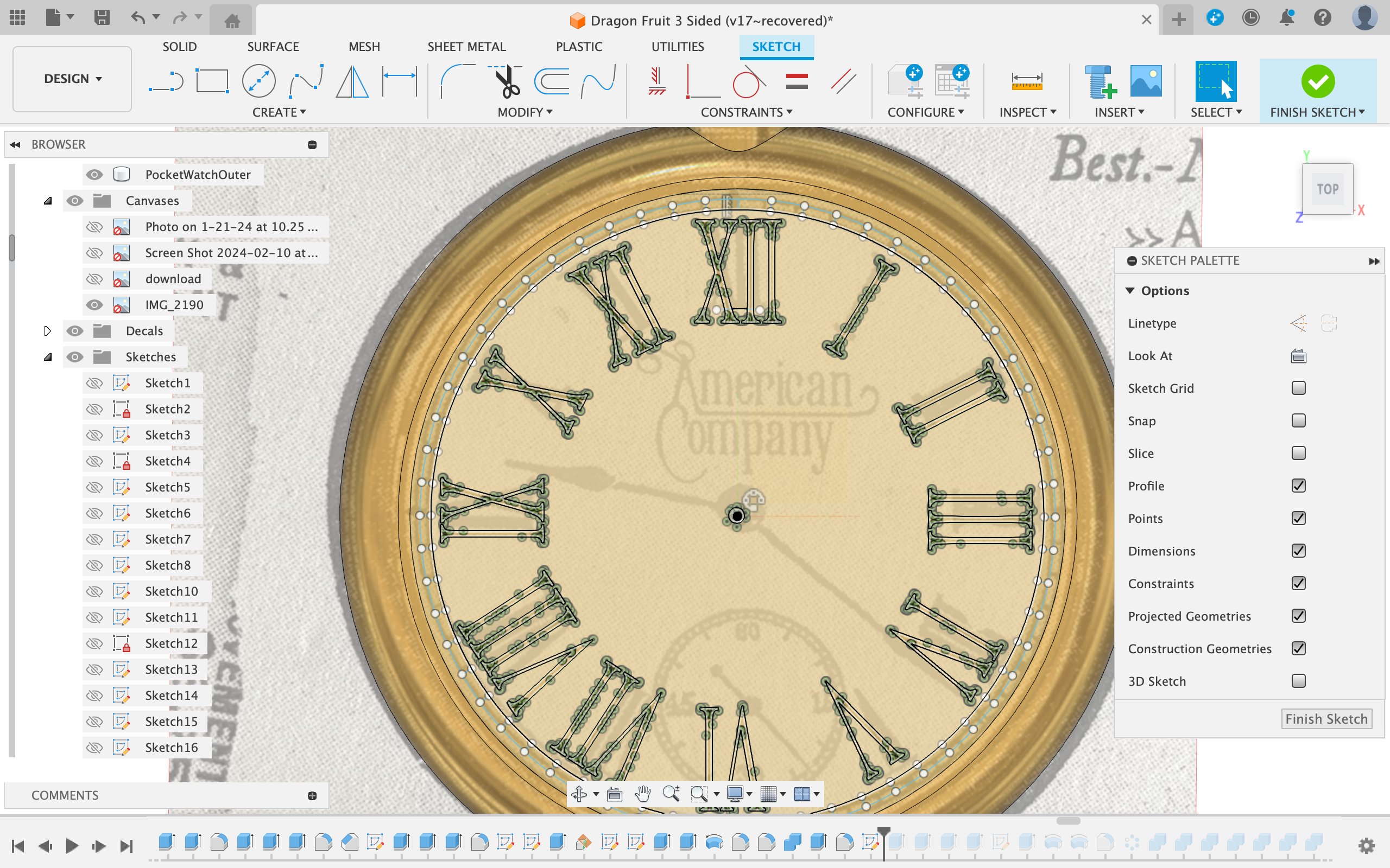
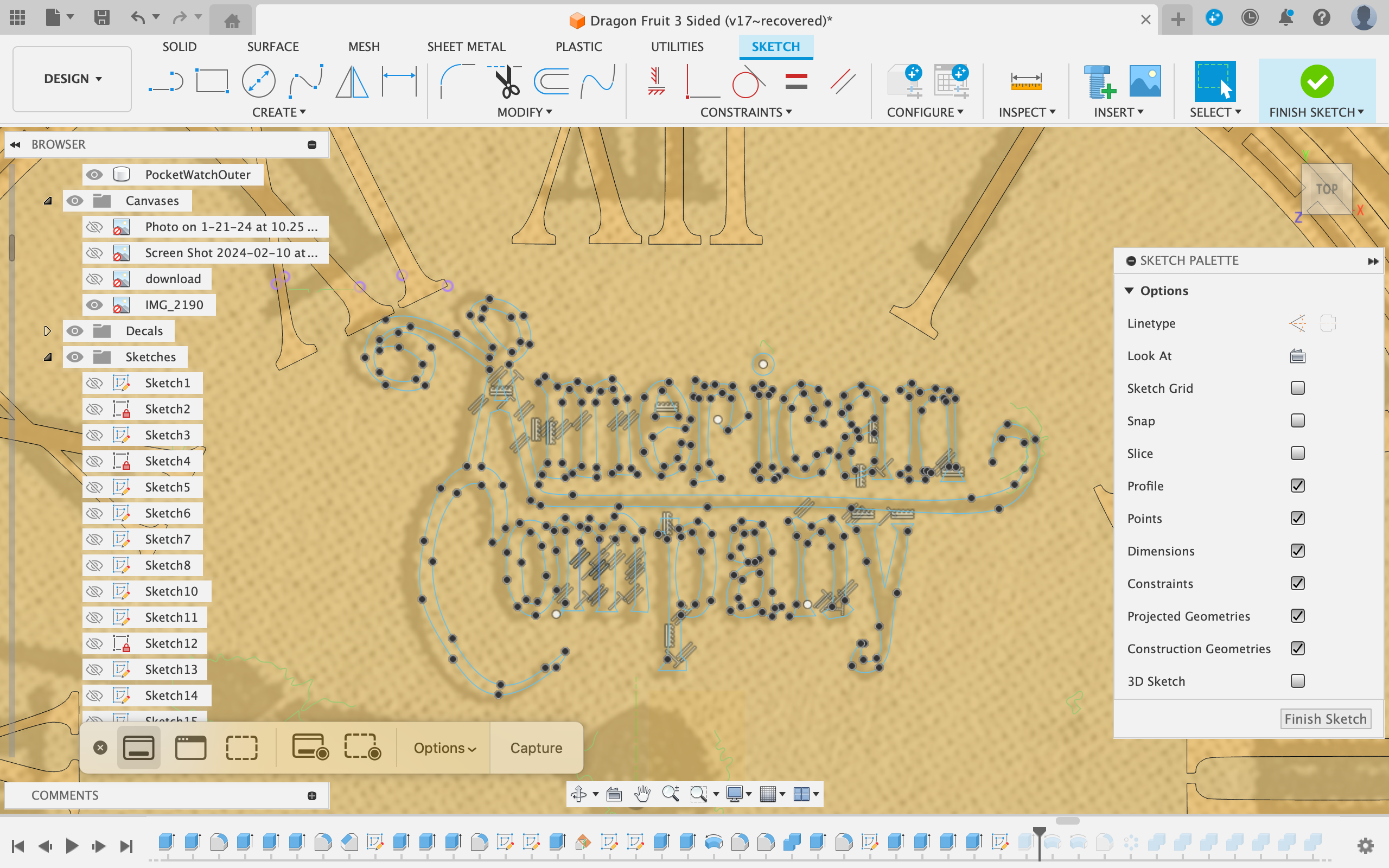
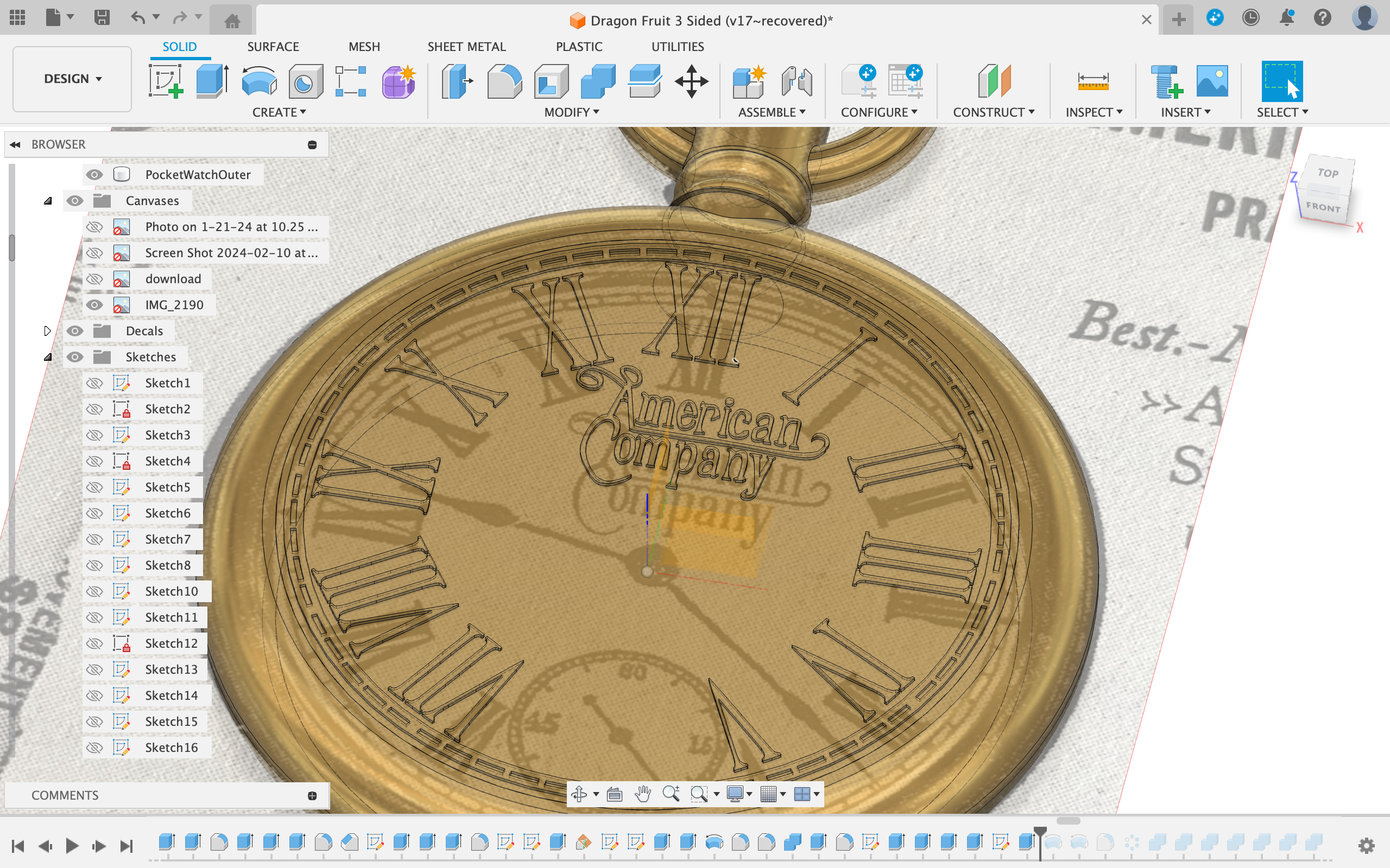
To create the text I created a sketch on the top of the clock and imported an svg of roman numerals on a clock.(alternative: trace the numerals using lines and splines)
To create the outer markings to determine the minute on the clock I created 2 large circles (as seen in the picture).
Then I created a line from one circle to another and patterned it 60 times around the center.
After that, I traced the logo (American Company) using the spline tool.
Finally I traced the hour hand and rotated it to be in a different, more open and 3D-printable position.
Extruding the Profiles
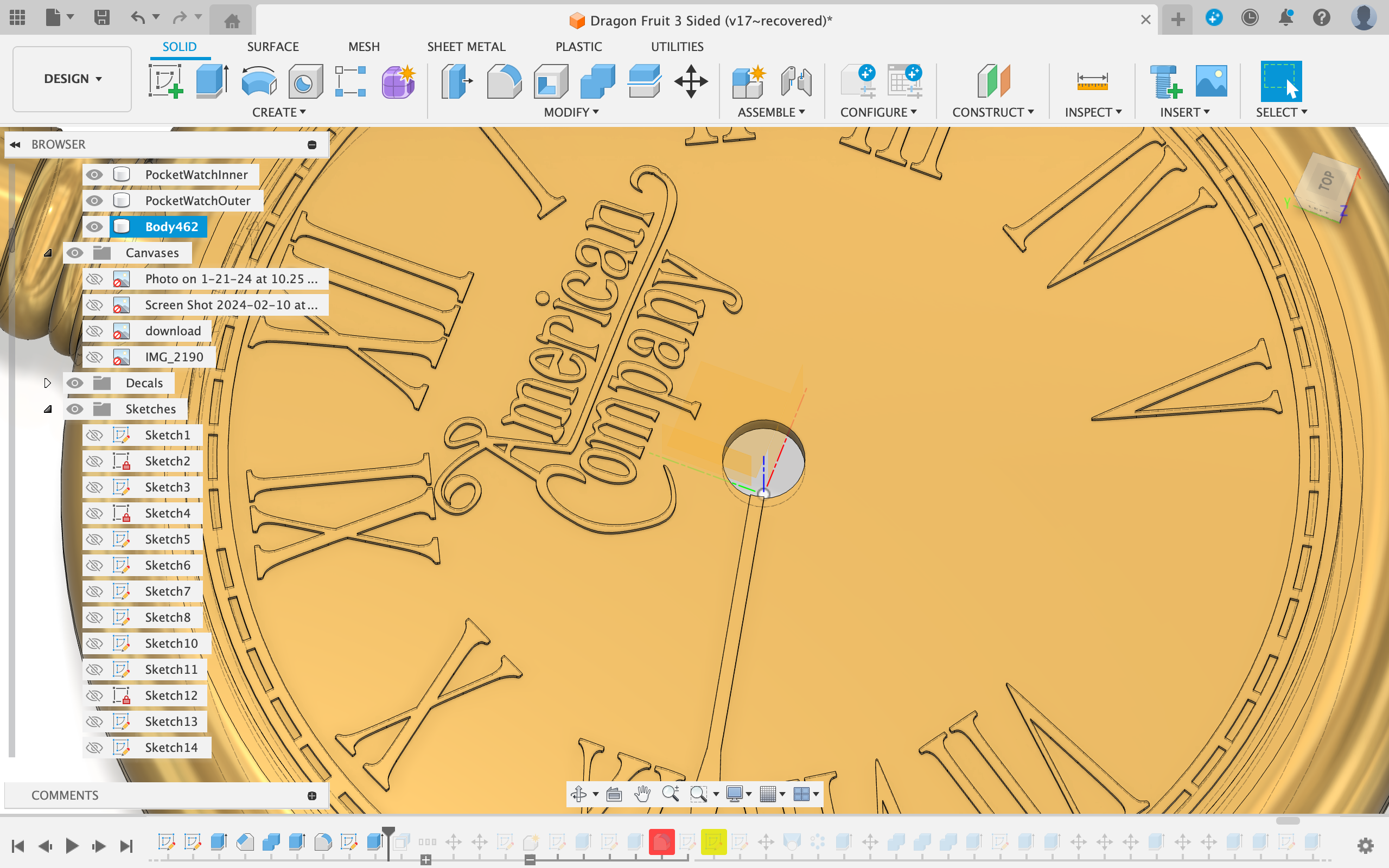
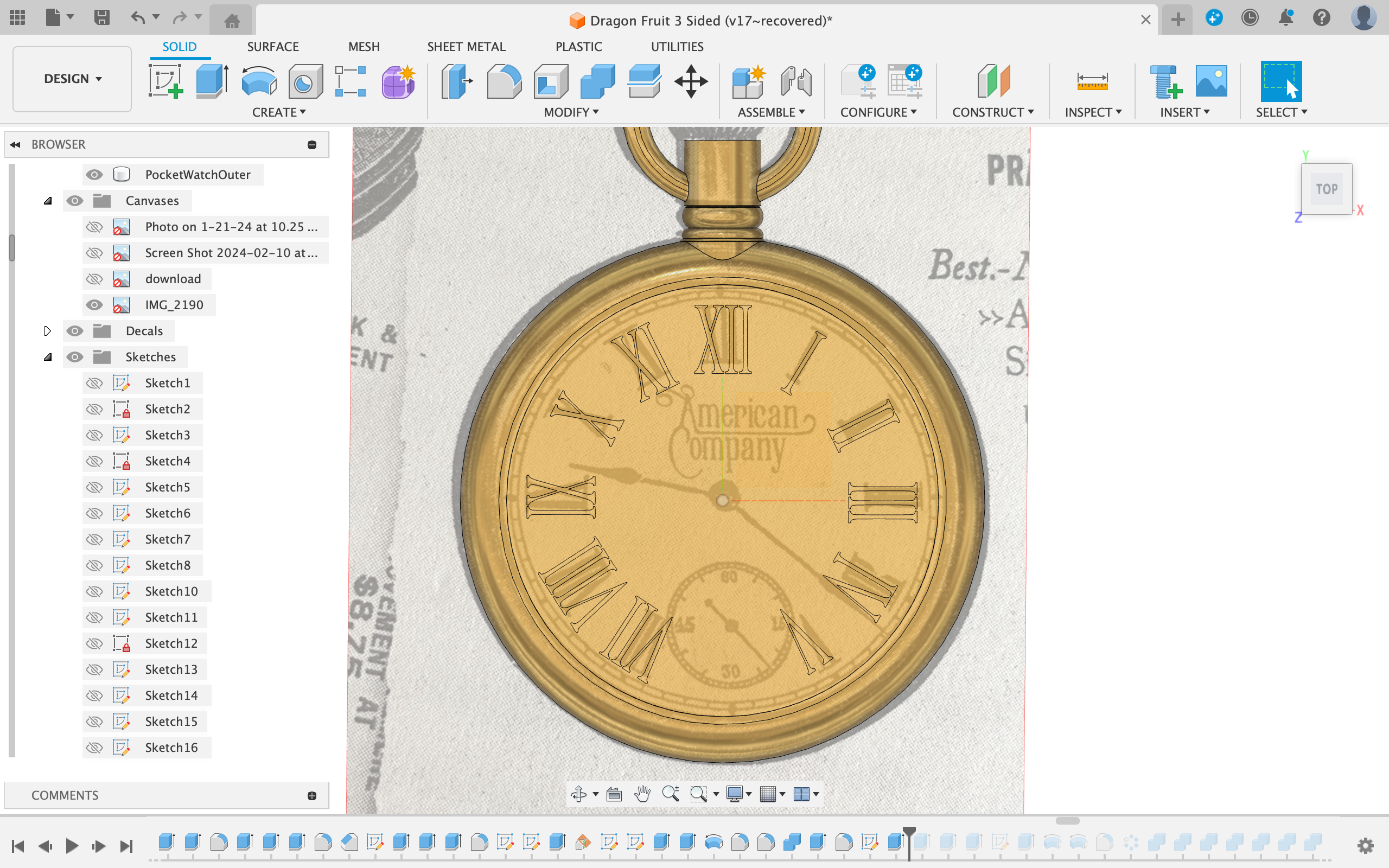
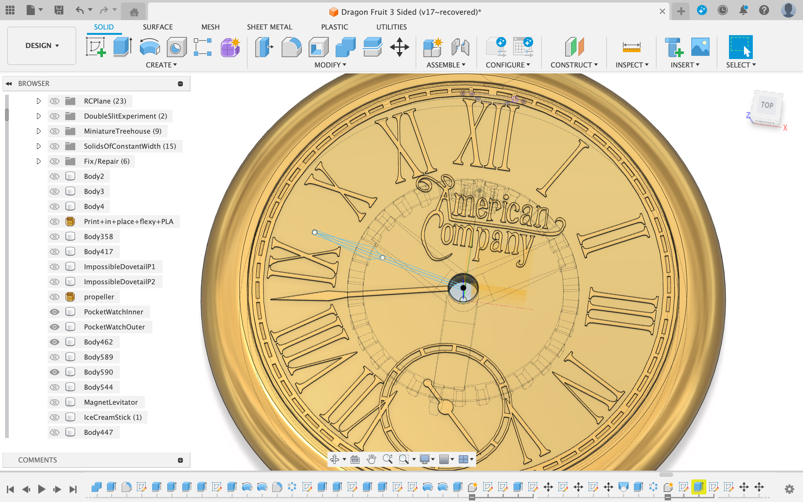
First, I extruded the American Company logo, the roman numerals, and the minute hand.
Then, I thin-wall extruded the markings on the outside.
Coming Up With a Mechanism
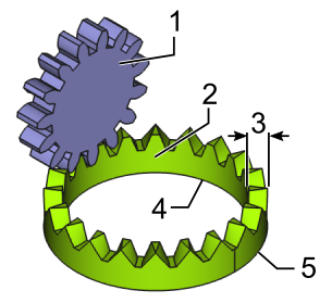
The clock in the book is broken and in the book, if you turn the winding crown the hour hand moves from the VII (7) to the IX (9) I decided to replicate this movement. To do this I decided to use crowned gears. Crowned gears (as the name implies) look a lot like crowns and have their teeth facing upwards. They can mesh perfectly with spur gears. To move from VII (7) to IX (9) in one rotation of the winding crown I'd have to use a 6:1 gear ratio. I chose to go with 5 teeth on the spur gear and 30 on the crowned gear.
Making the Spur Gear
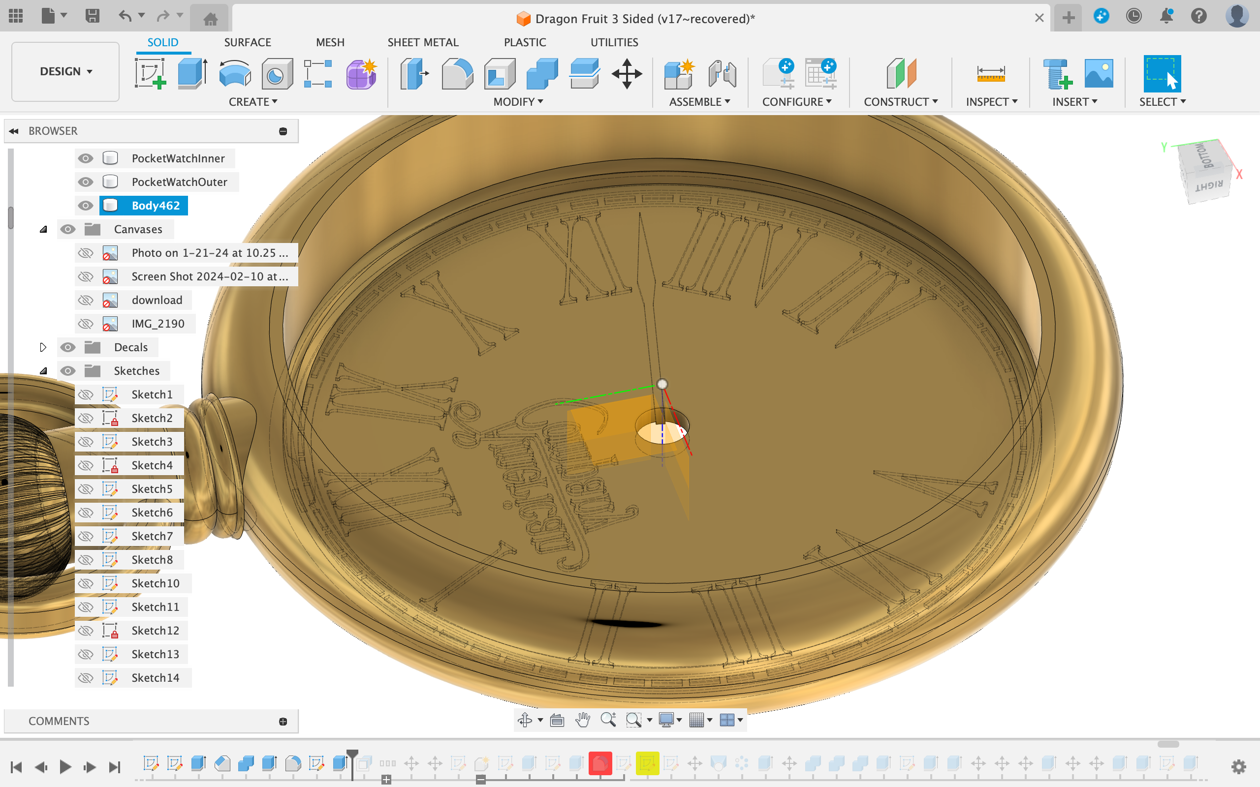
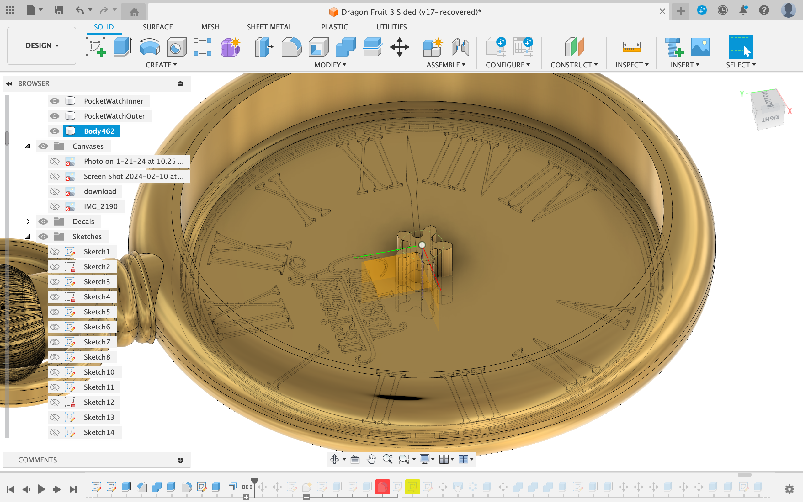
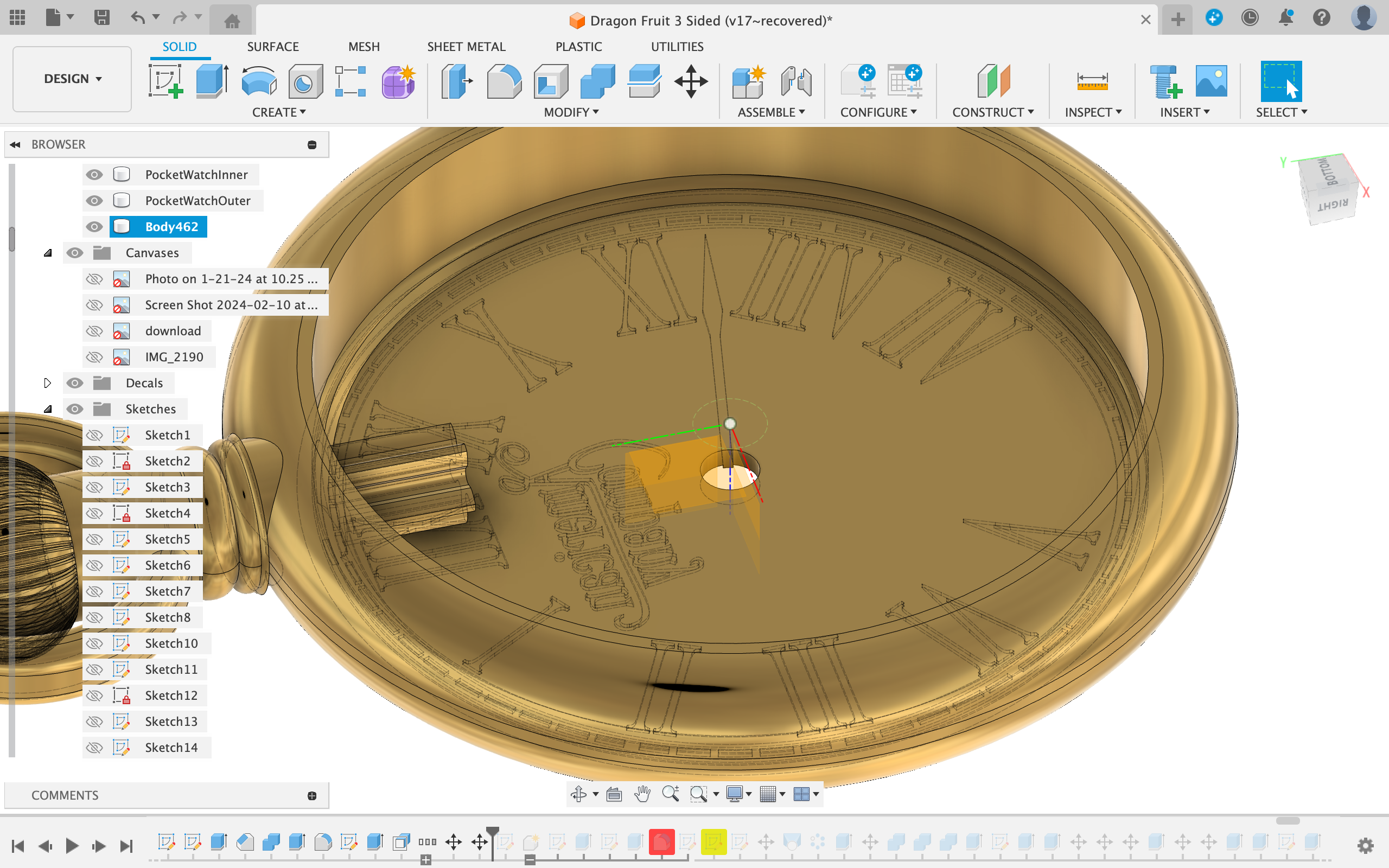
First I used the cut extrude function to make the part with the roman numerals on it thinner.
Then I created a 5 tooth, module 1.5 mm spur gear using Fusing 360's Spur gear function. (found under Utilities -> Add-Ins -> Scripts and Add-Ins -> Spur gear)
I positioned it to be roughly where it would be in the final model. (view picture)
I also decide to cut a 1.4 mm hole to stick a 1.2 mm metal shaft through to serve as an axle.
I also cut the same hole into the center of the winding crown and made sure the hole went most of the way through.
Making the Crowned Gear
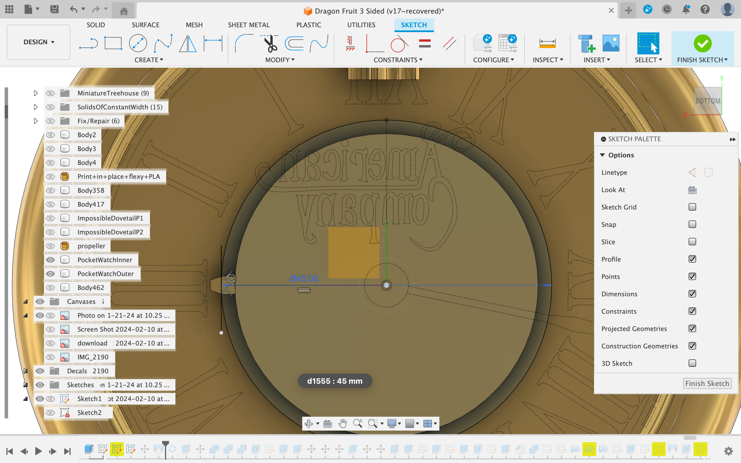
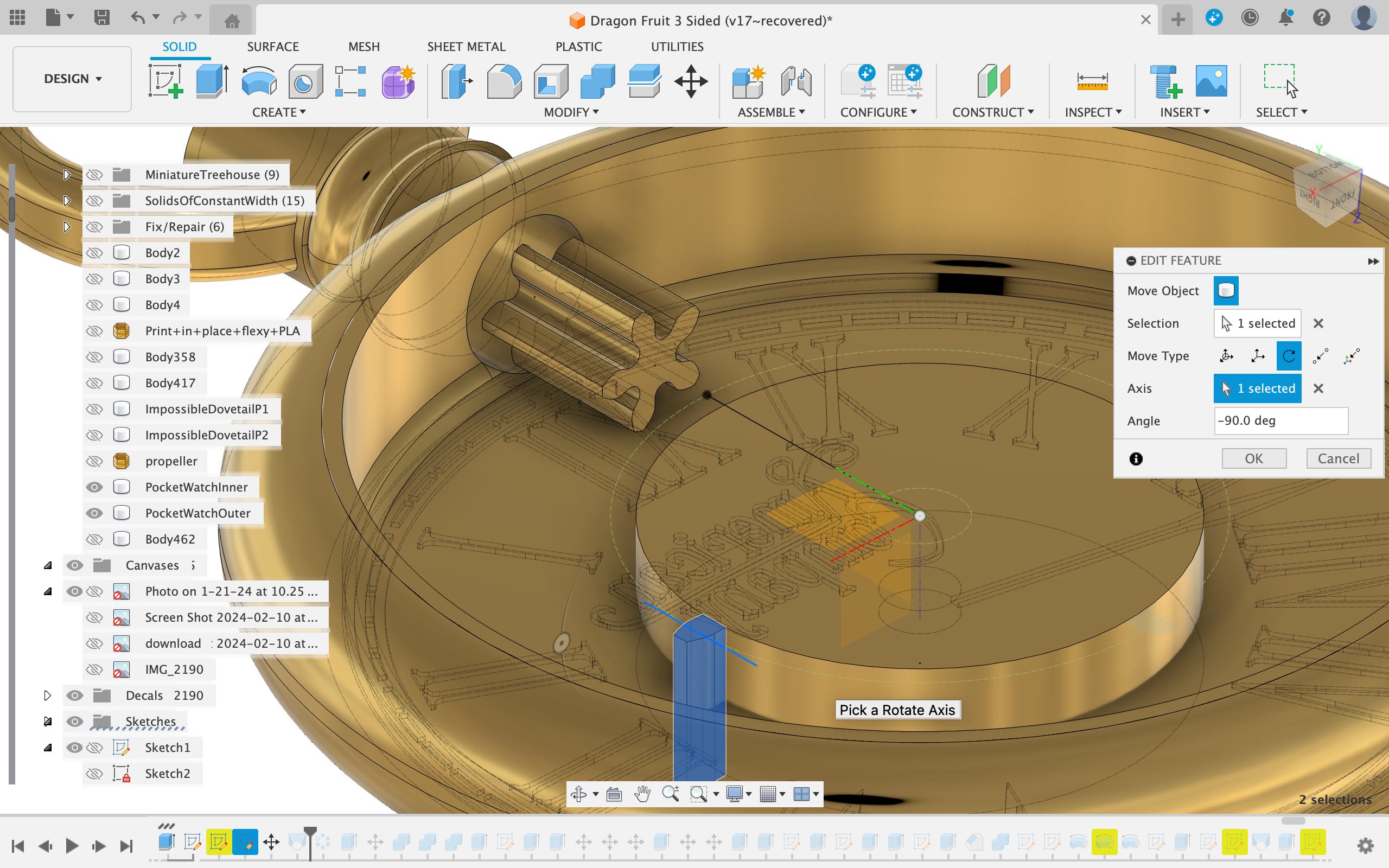
I started by creating another spur gear with the same module but this time with 30 teeth.
I expanded the group in the timeline and deleted the pattern the tooth around the cylinder step.
Next, I created a sketch on the center cylinder.
After that, I sketched a circle with a diameter of 30 (teeth number) * 1.5 (module) = 45 mm.
I created a line from the center of the circle to the outside of the circle on the small tooth.
Then, I created a line perpendicular to the first line (our axis on which to rotate the tooth).
Afterwards, I rotated the tooth around the axis 90 degrees.
Making the Crowned Gear Part 2
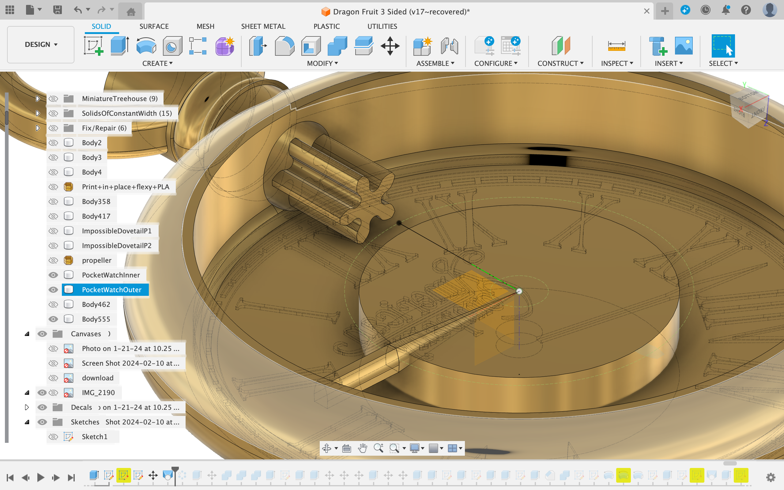
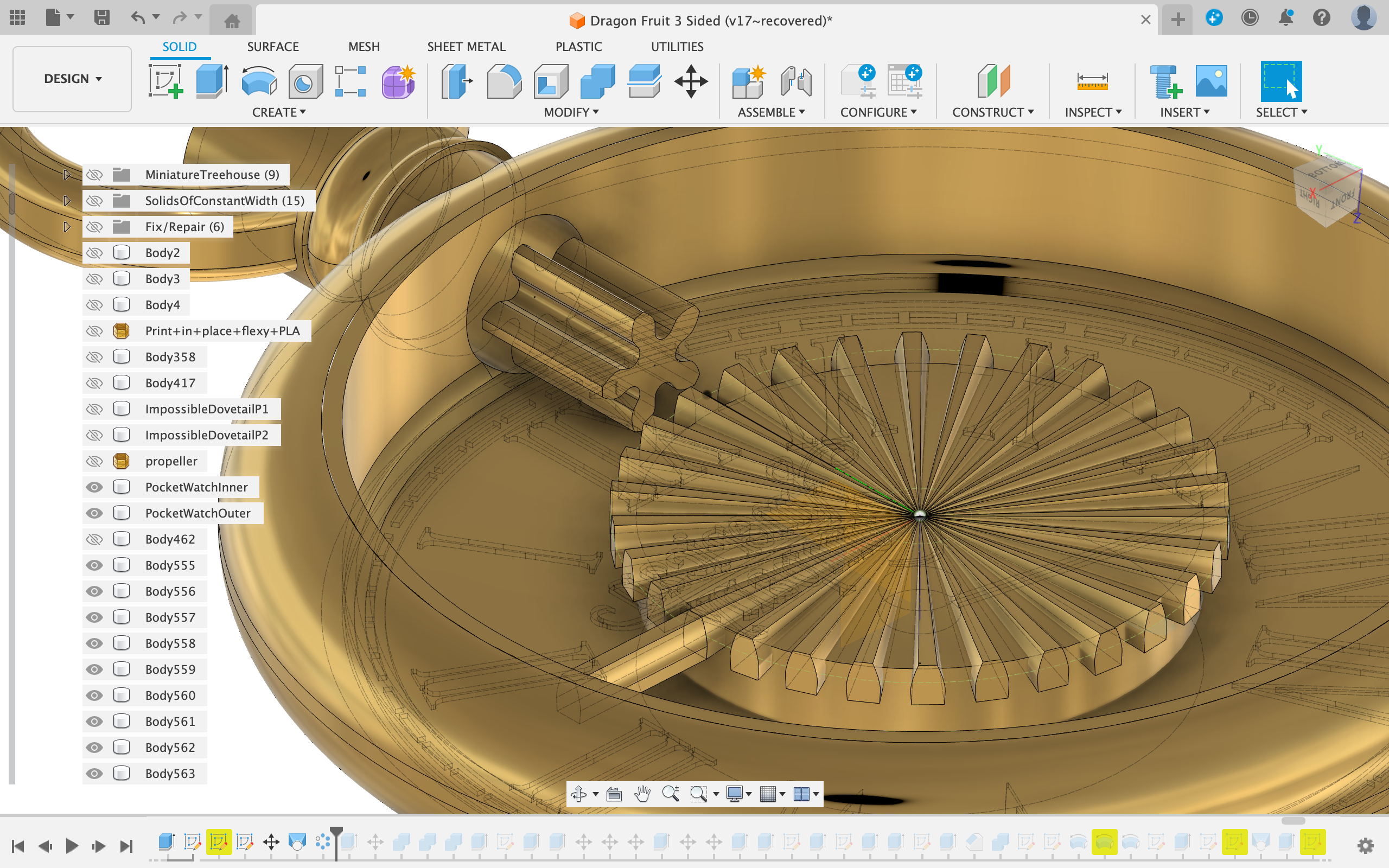
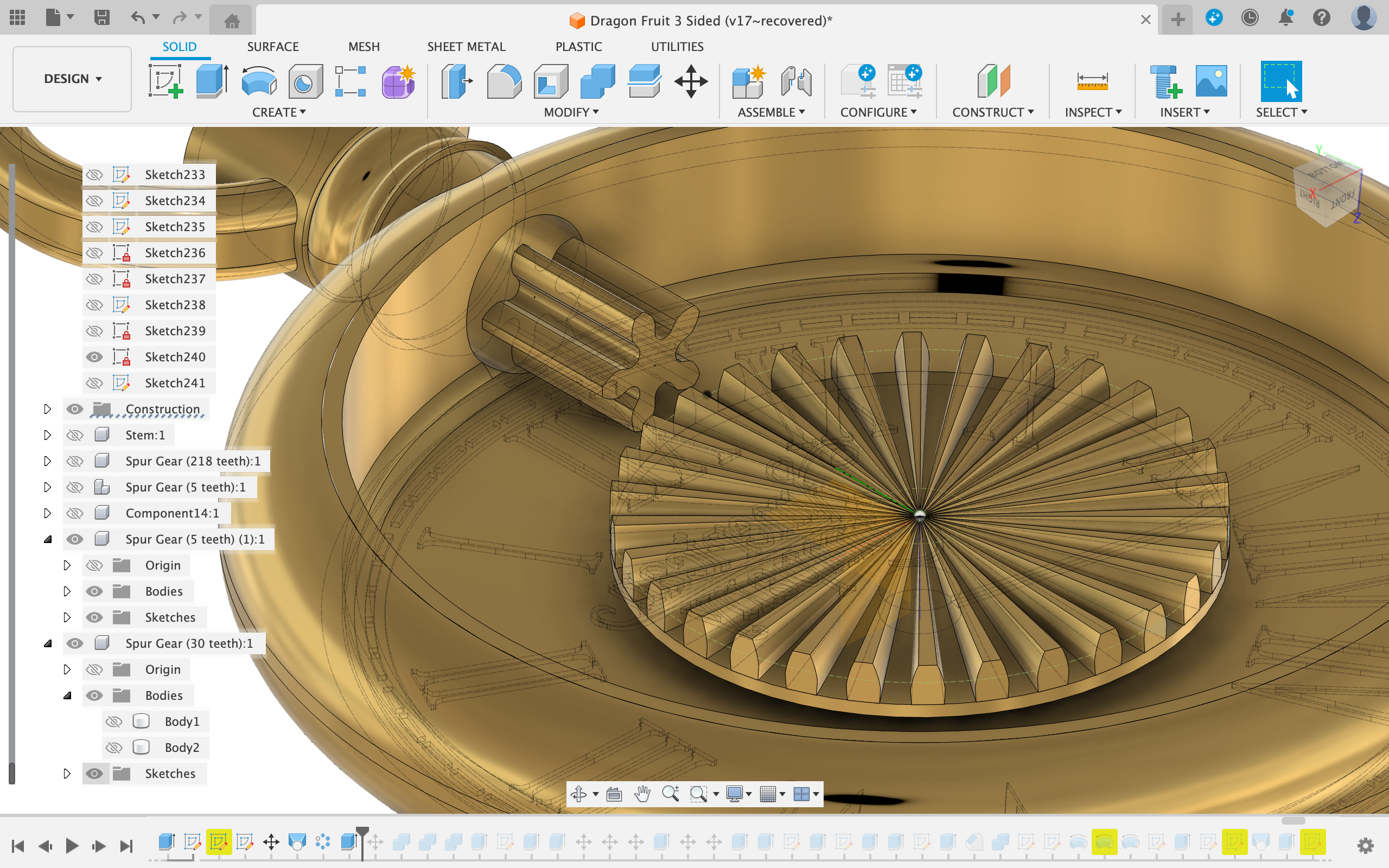
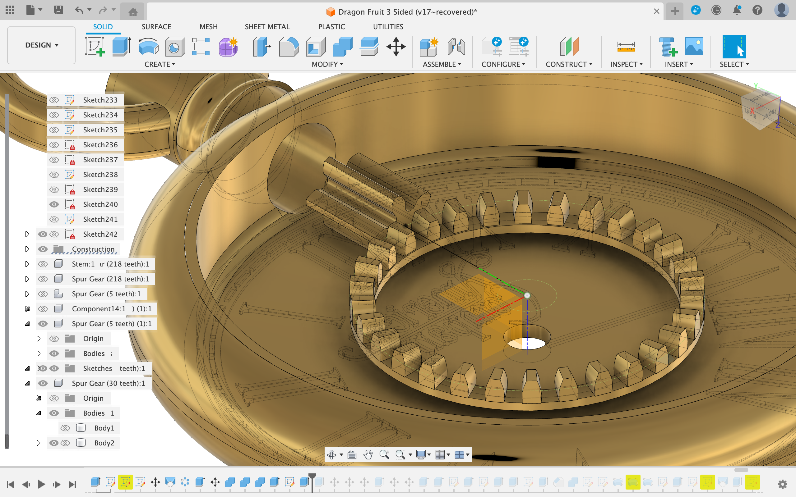
Now I lofted the front part of the gear with the center of the gear. (the origin in my case)
Then I patterned the loft 30 times around the circle.
I adjusted the baseplate for the gear using the press pull function to fit the current arrangement of teeth.
Next I cut a large hole through the middle of the crown gear to save printing material.
The Shaft and Hour Hand
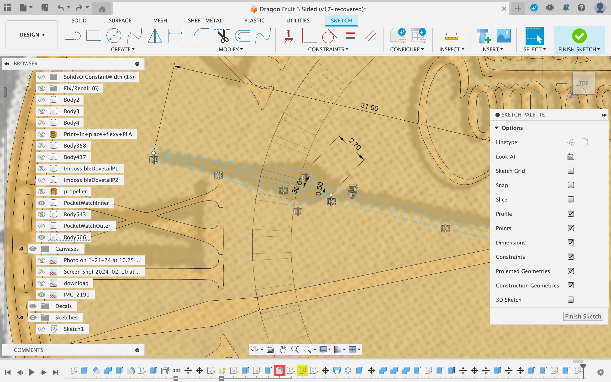
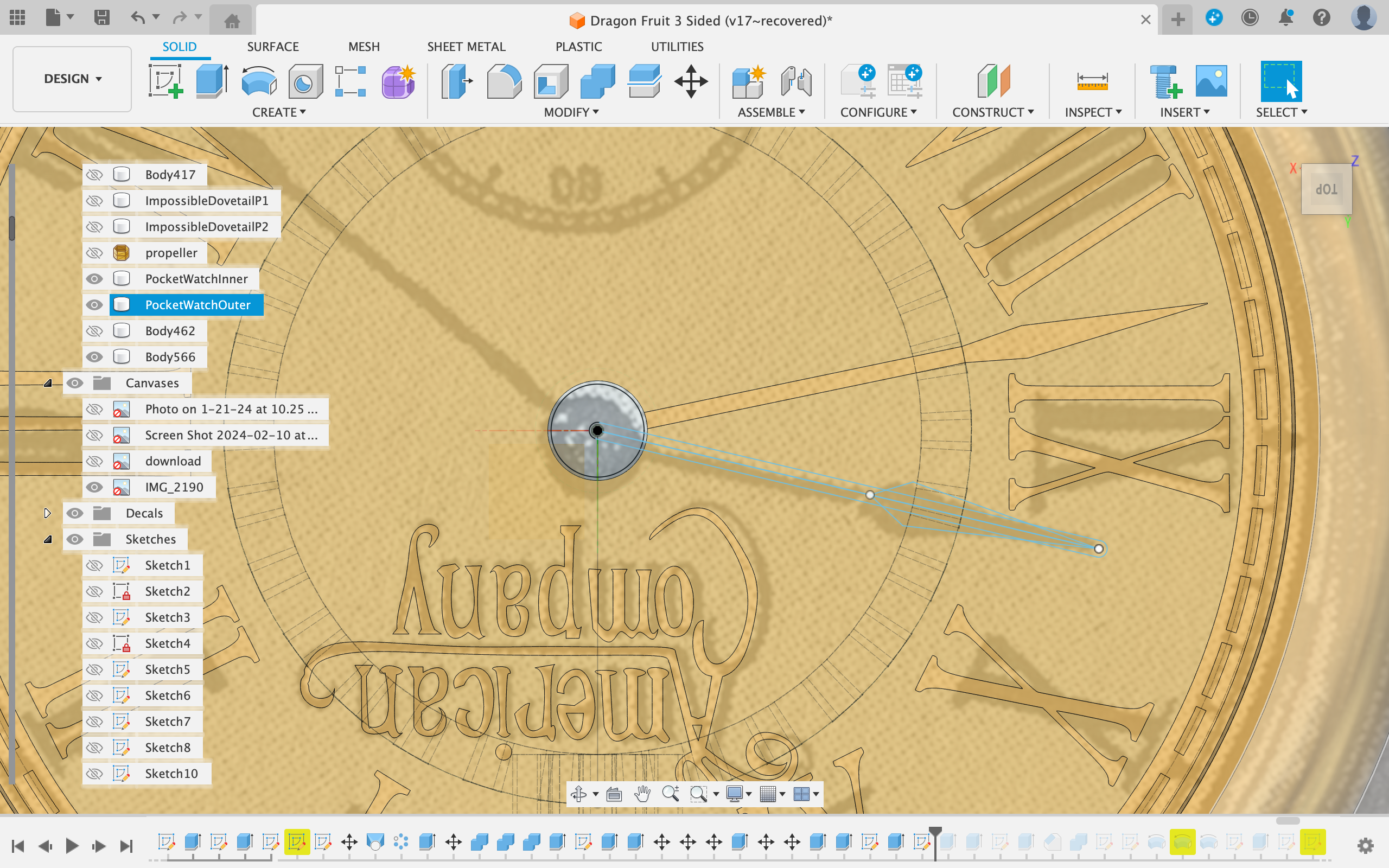
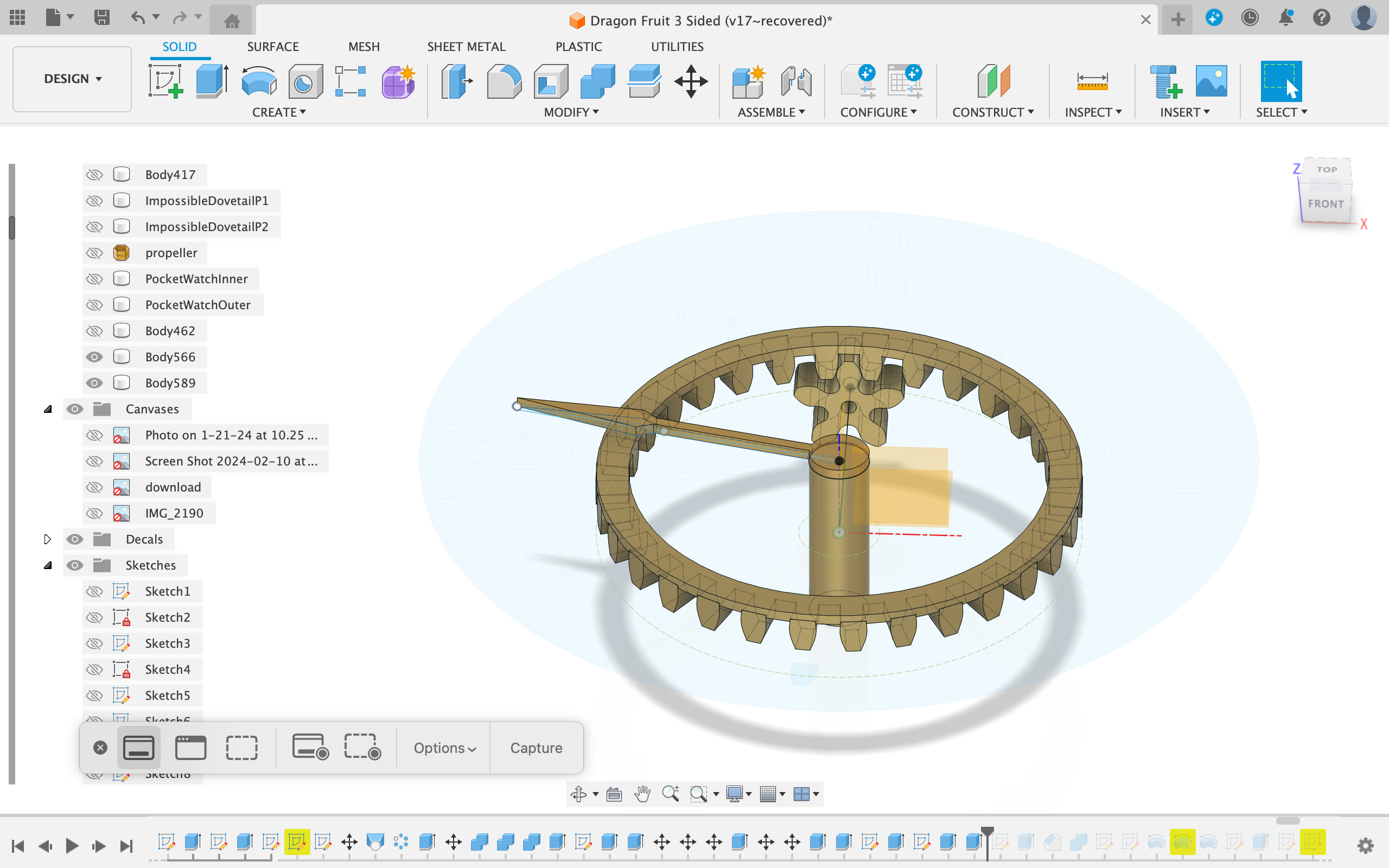
To create the shaft I cut a 6mm diameter hole in the center of the disc.
Then I traced the hour hand from the original picture and also traced the shaft.
I extruded the hour hand 1mm up and the shaft 16 mm down.
Crown Gear Shaft Connection
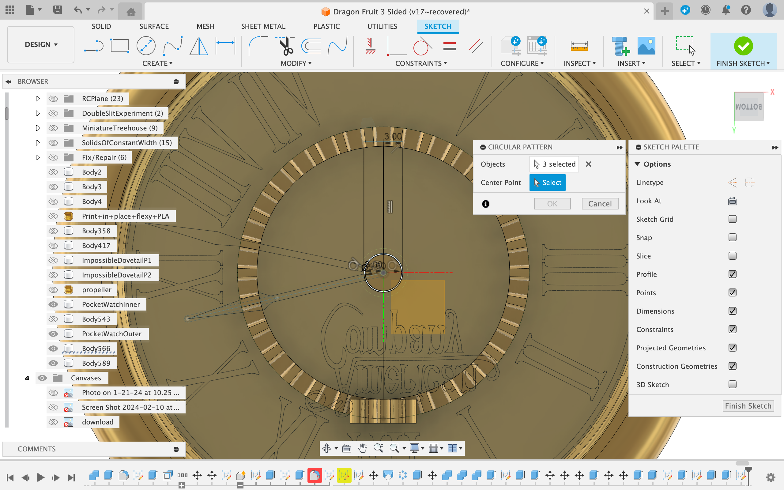
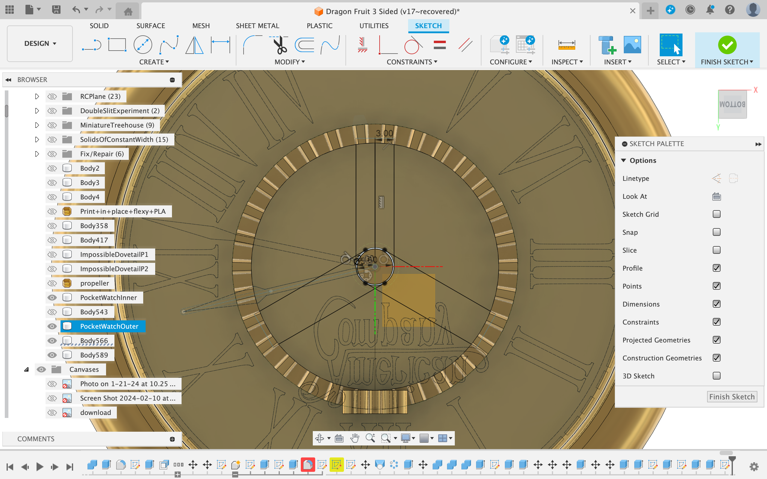
To connect the crown gear to the shaft. I decide to sketch a 2 mm wide ring with an inner diameter of 6mm.
Then I added three "spokes" to connect the ring to the crown gear. (I drew only a single spoke and patterned it 3 times around the center)
I extruded the ring 5mm and the spokes 3 mm.
Backplate
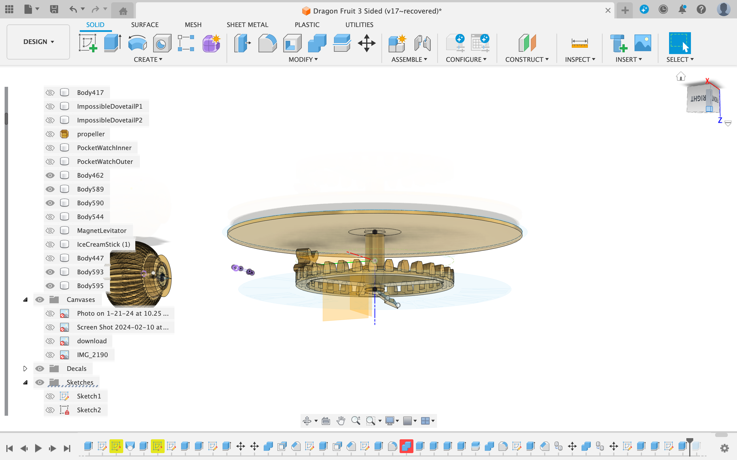
To design the backplate, I simple created a sketch and drew a circle with a diameter to cover the back of the watch.
Then I added a 6mm diameter circle concentric to the first.
Afterwards, I extruded the ring 2 mmm.
Printing
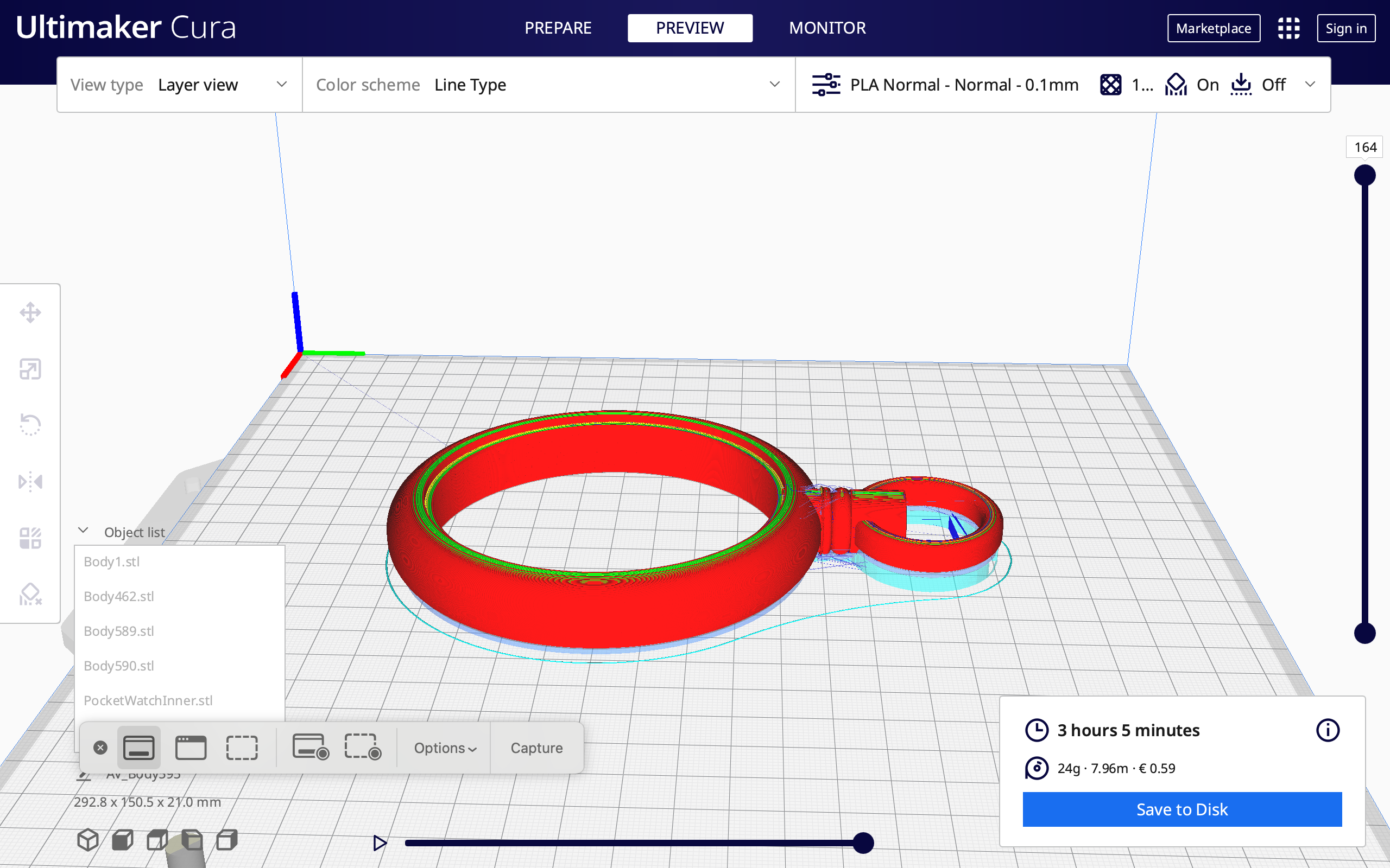
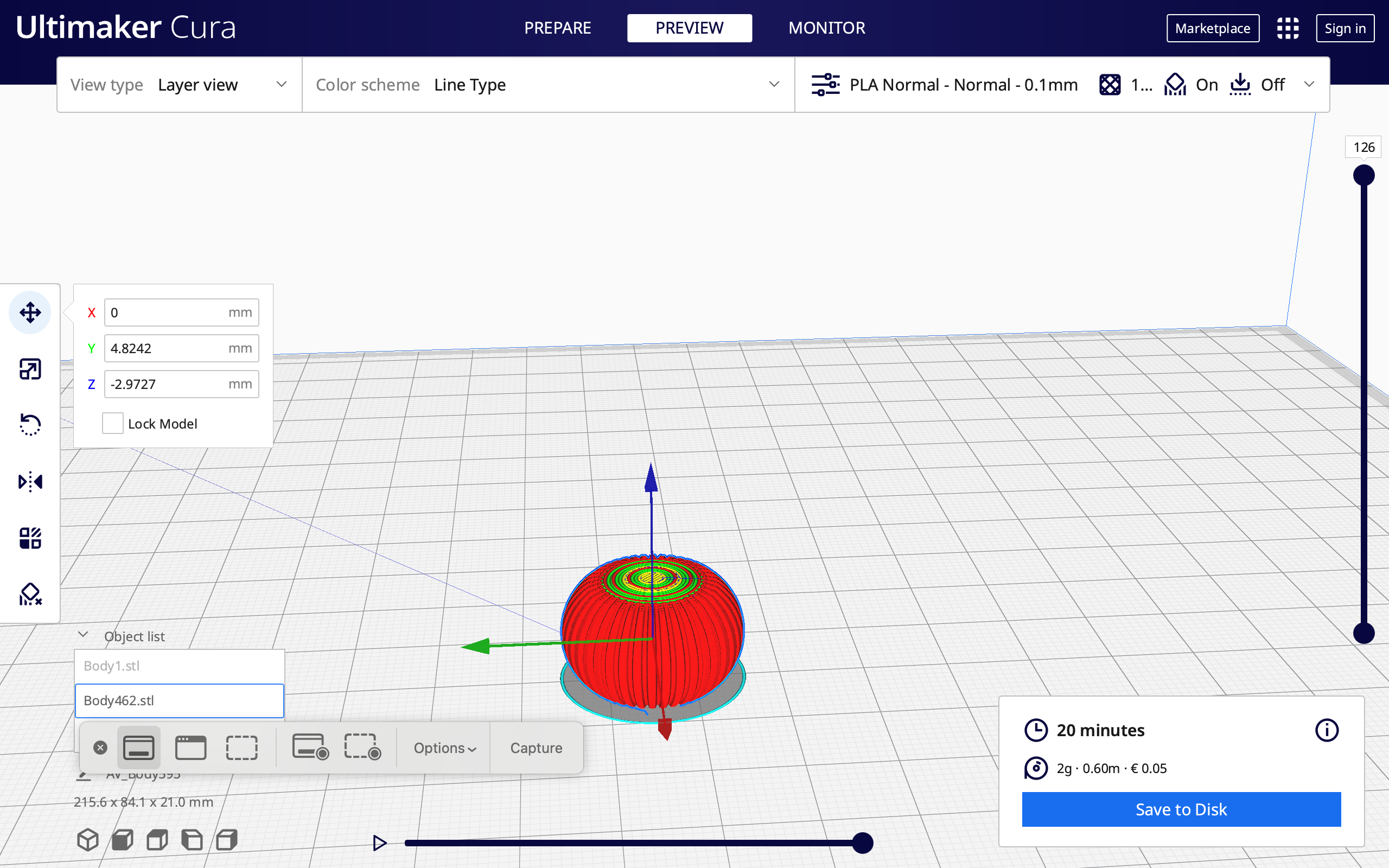
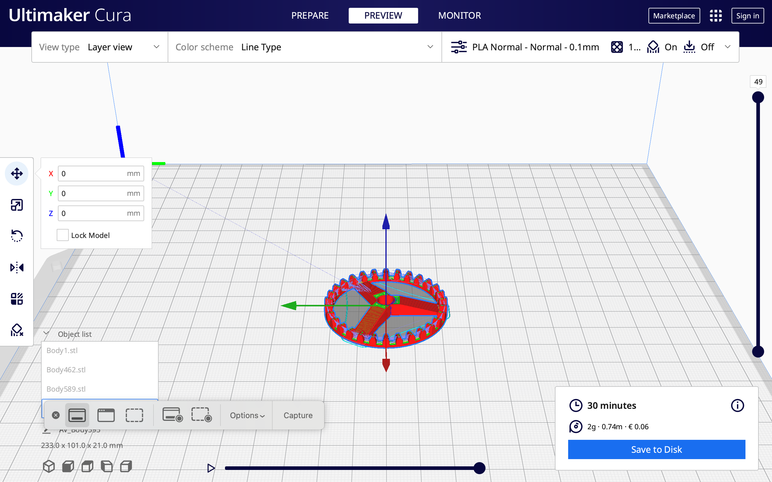
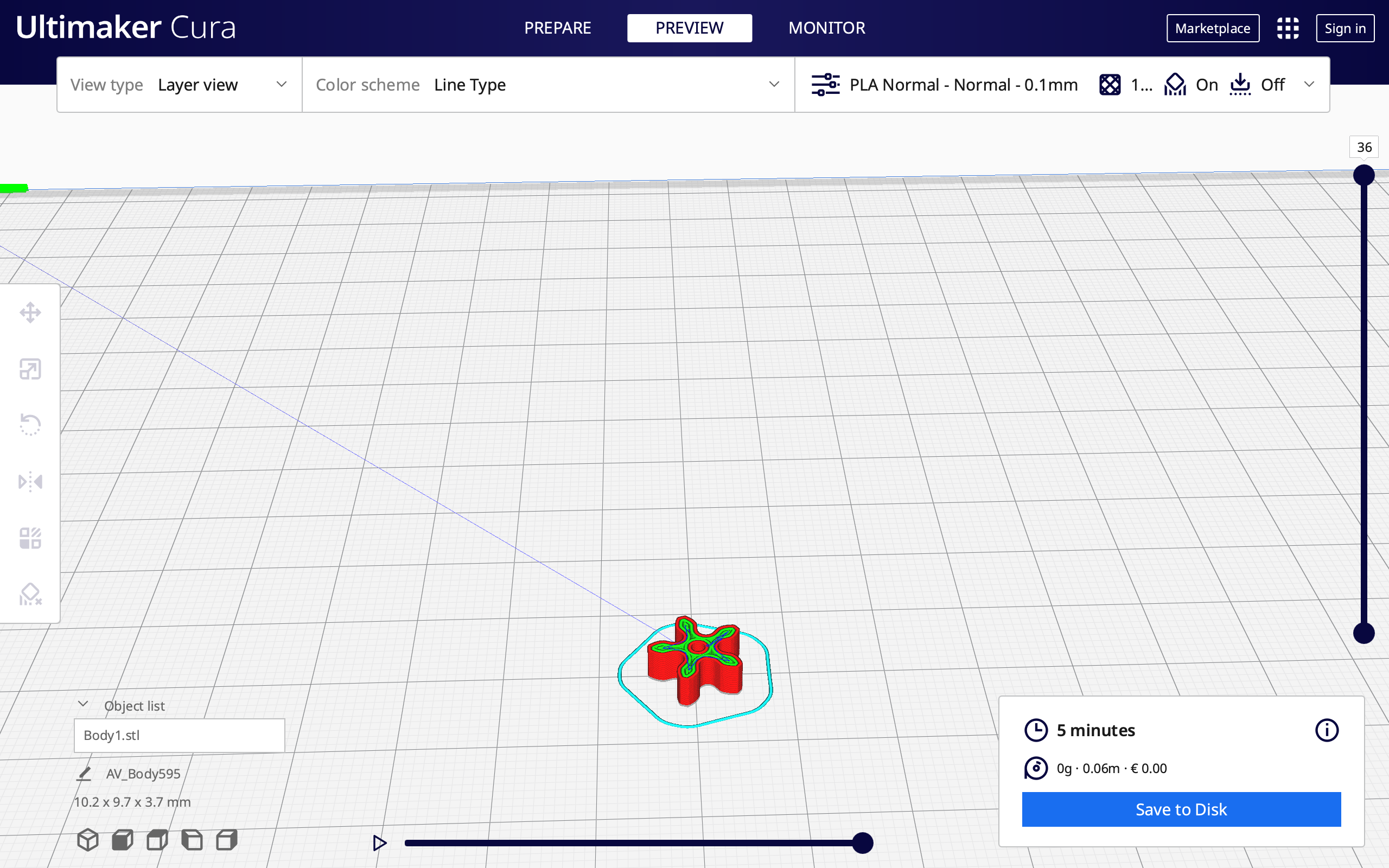
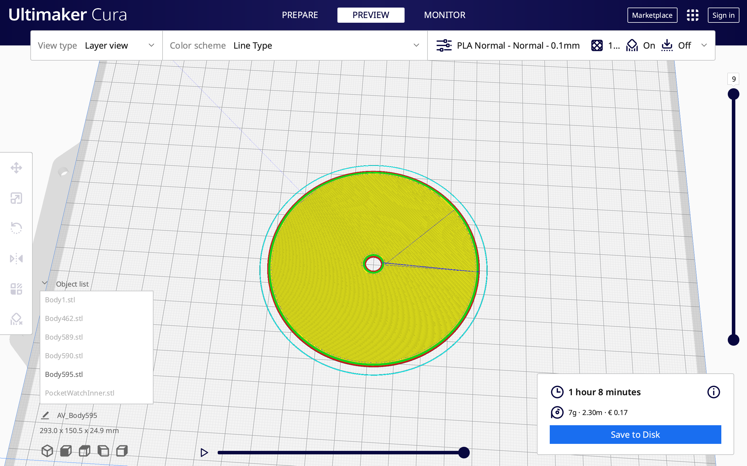
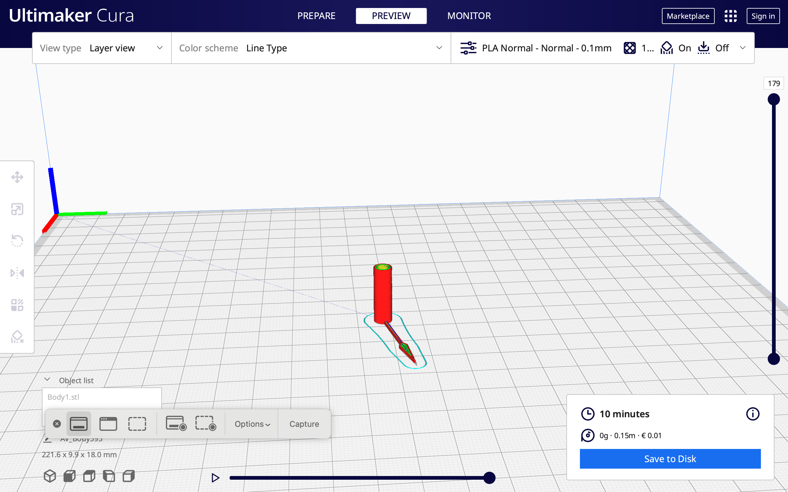
Outer Case of the Watch : Print the outer case of the watch lying down (picture 1)
Material : PLA Gold
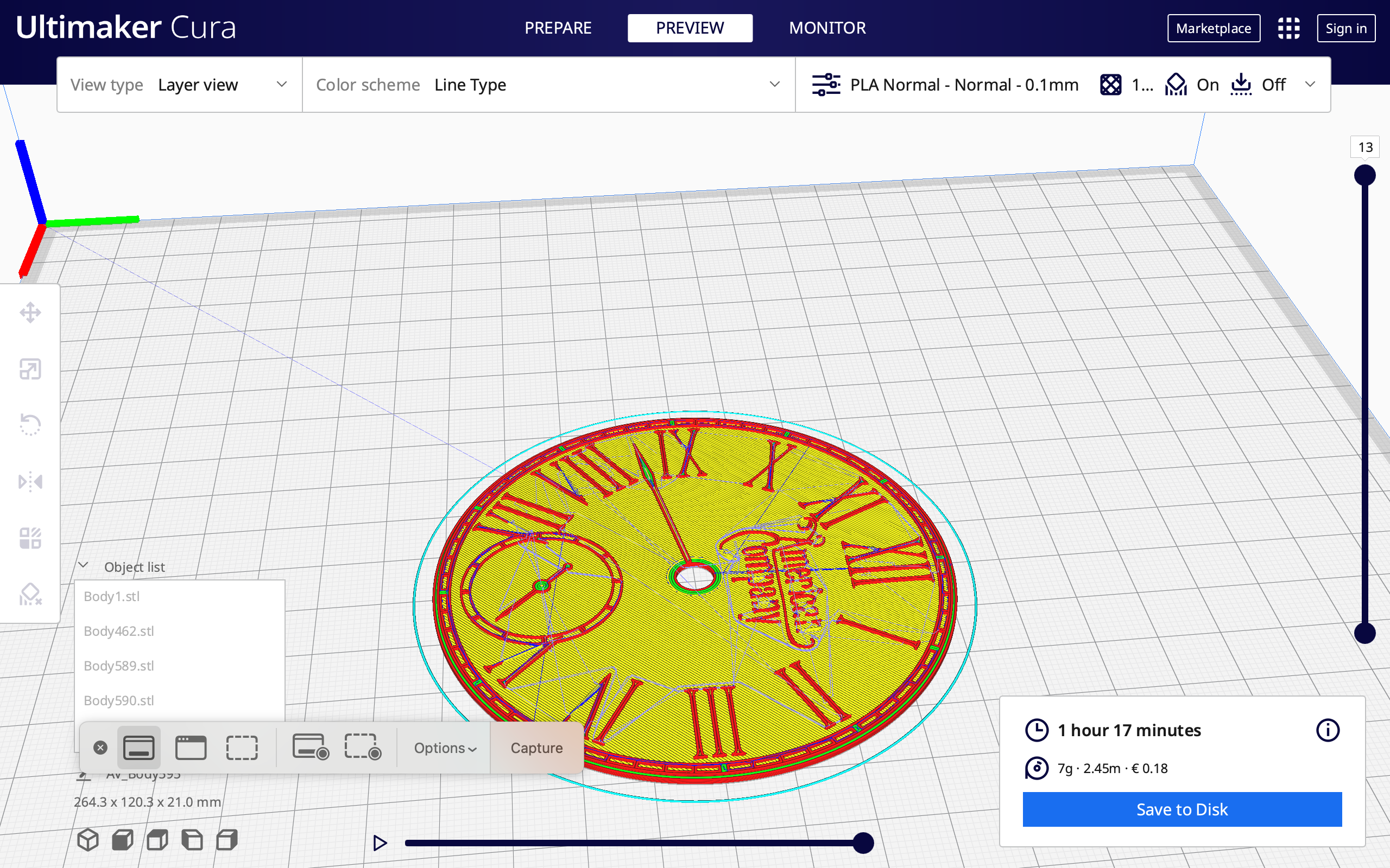
Plate with the numerals : Print as is. Change the color midway through the print (catch the right moment when the printer starts doing letters and switch the filament to black) (Picture 2)
Material : PLA White and Black
Winding Crown : Print it upside down. (Picture 3)
Material : PLA Gold
Gears: Print Flat (Pictures 4 & 5)
Material : PLA White
Backplate : Print as is. (Picture 6)
Material : PLA Gold
Hour Hand : Print with the hour hand facing down (Picture 6)
Material : PLA Black
Assembling and Making Changes
Assemble the clock like in the Fusion 360 File :
- Glue the front plate to the outer casing
- Slide the hour gear onto the front plate
- Press the crowned gear into the hour hand shaft
- Cut a 60 mm wire and connect the small spur gear to it
- Slide the Winding Crown in place and press the wire with the spur gear on it through the connecting tube into the hole on the winding gear
- Put on the Baseplate
Making Changes :
If anything doesn't fit, you can use sandpaper or modify the part in Fusion 360 using the press pull feature and reprint it.
Done
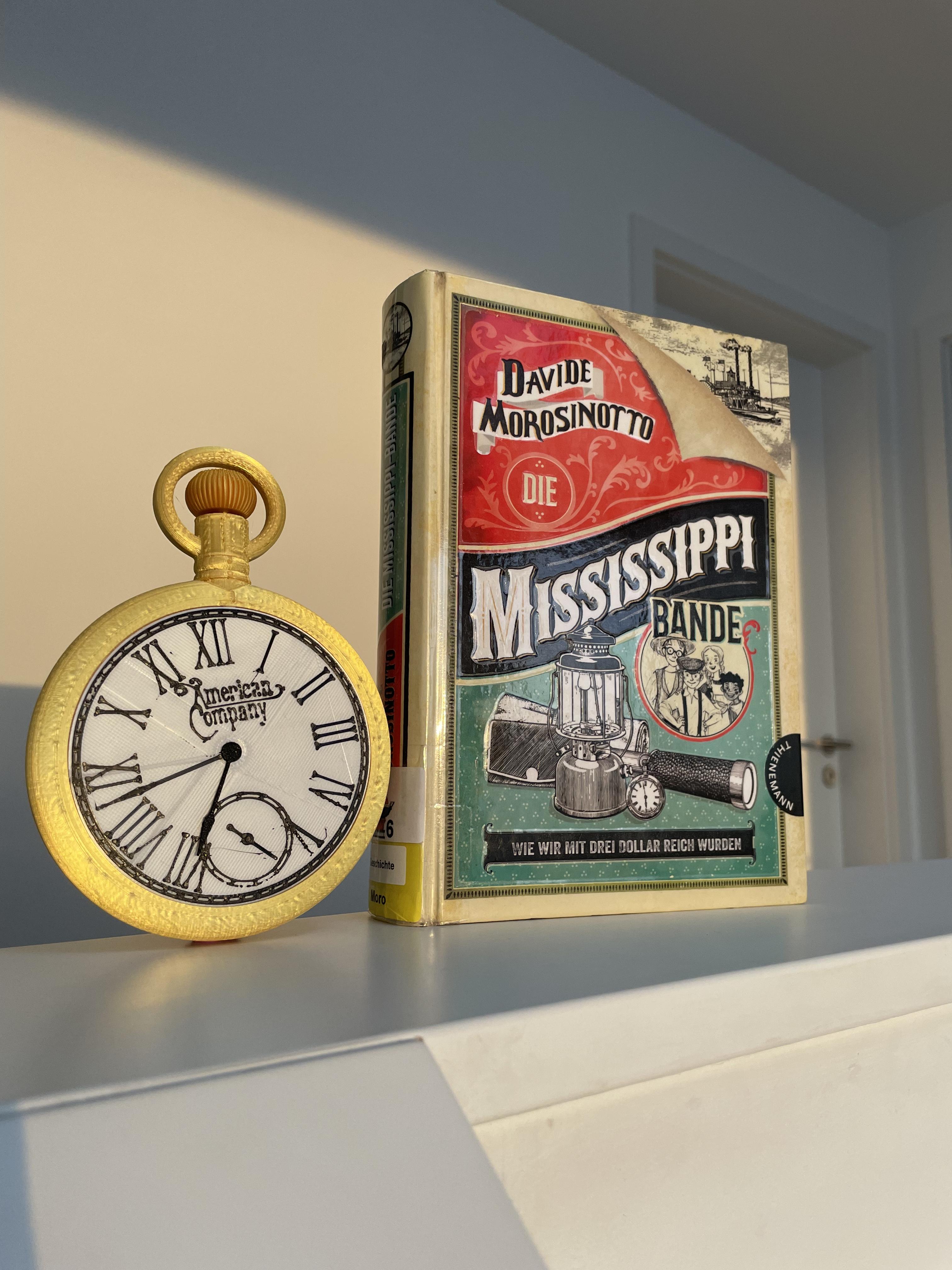
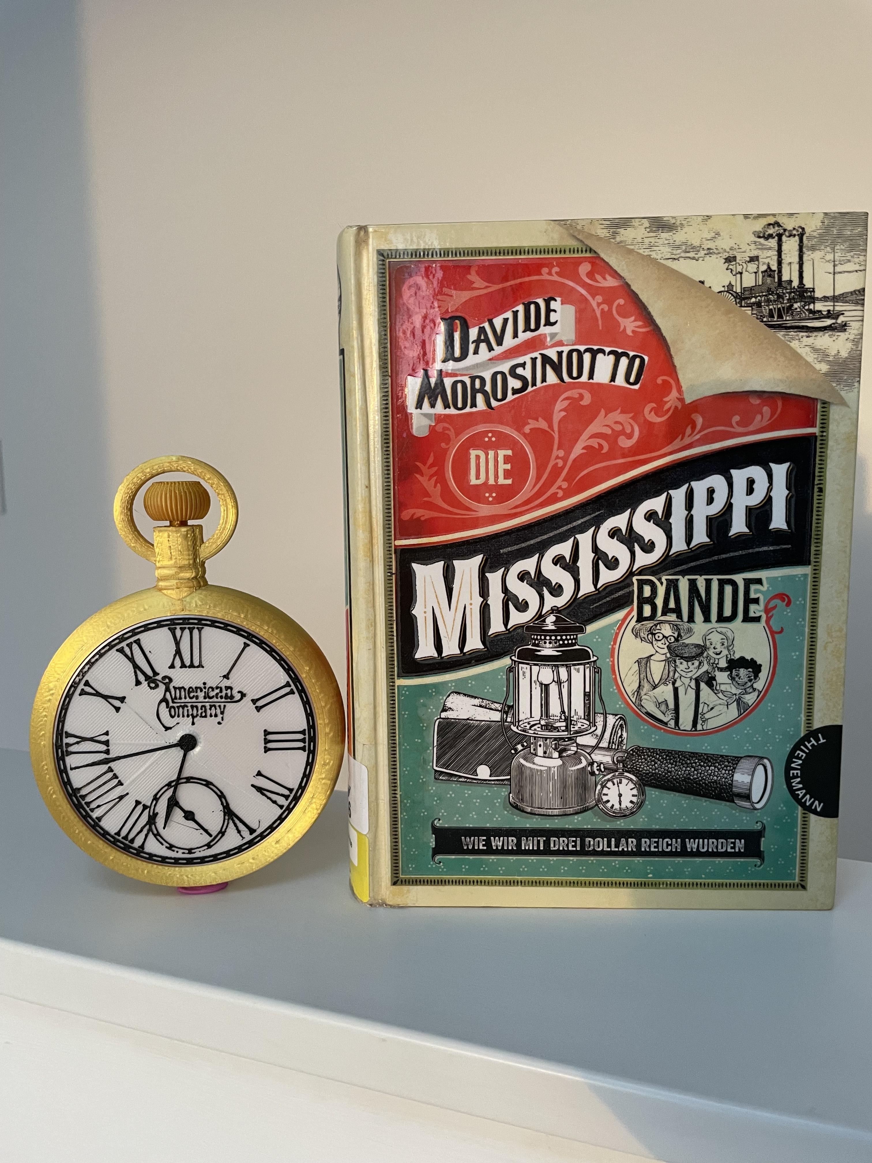
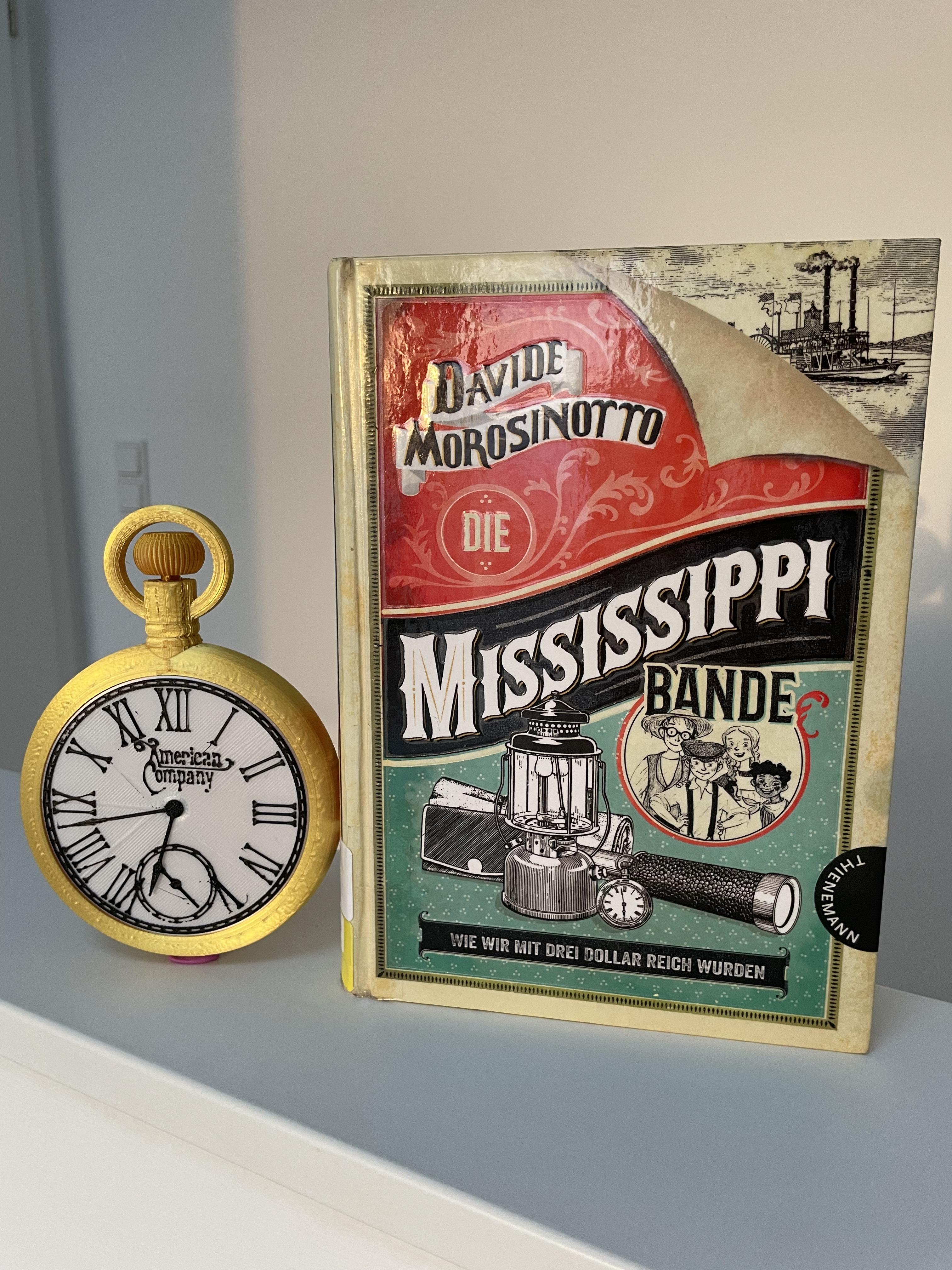
Now you're done.
Click below to watch a video of the final watch.