3D Printed Mouse - Vaxee Outset AX Inspired - Ajazz I305 Internals
by MechaMouse in Workshop > 3D Printing
1846 Views, 13 Favorites, 0 Comments
3D Printed Mouse - Vaxee Outset AX Inspired - Ajazz I305 Internals
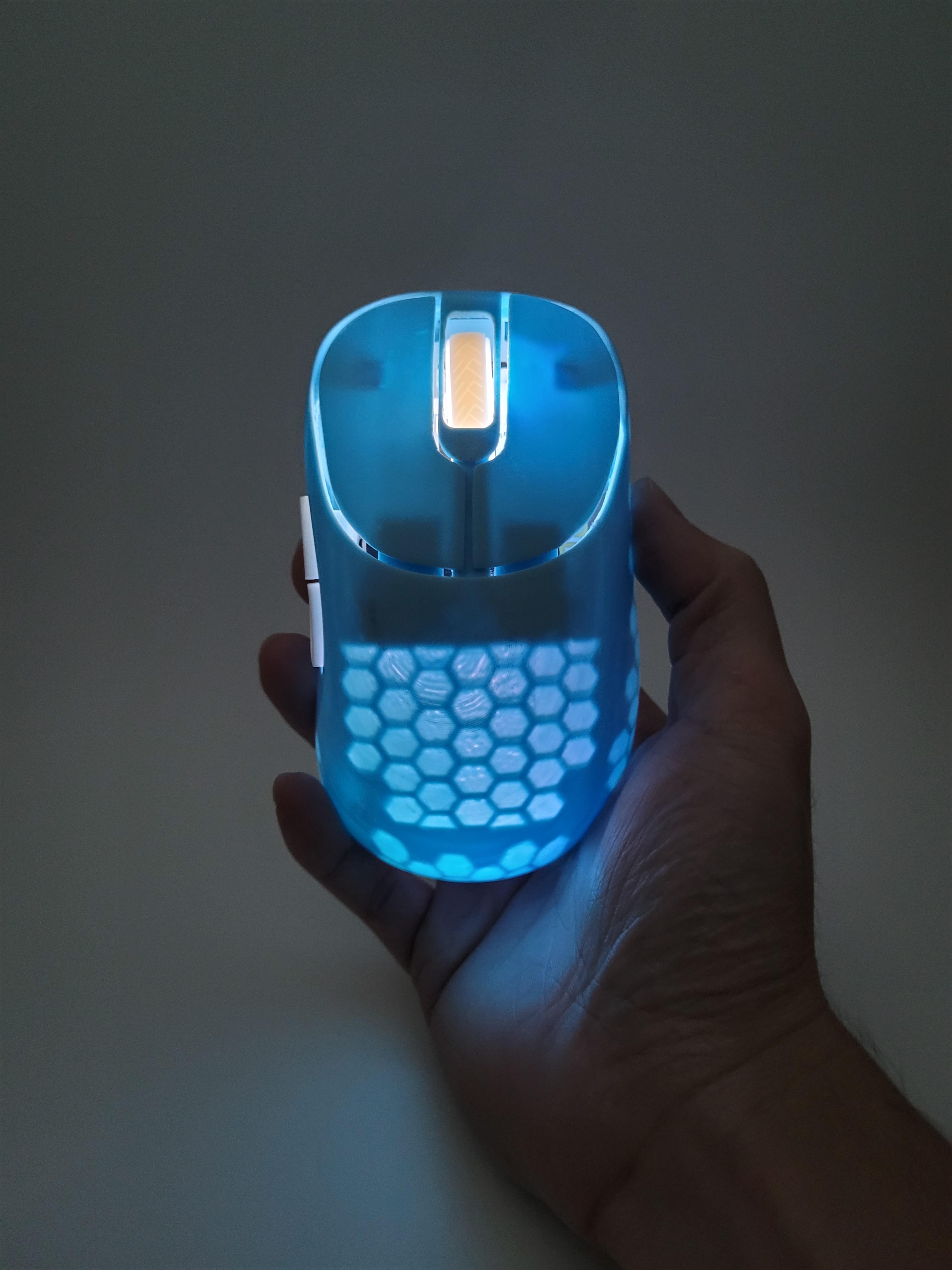
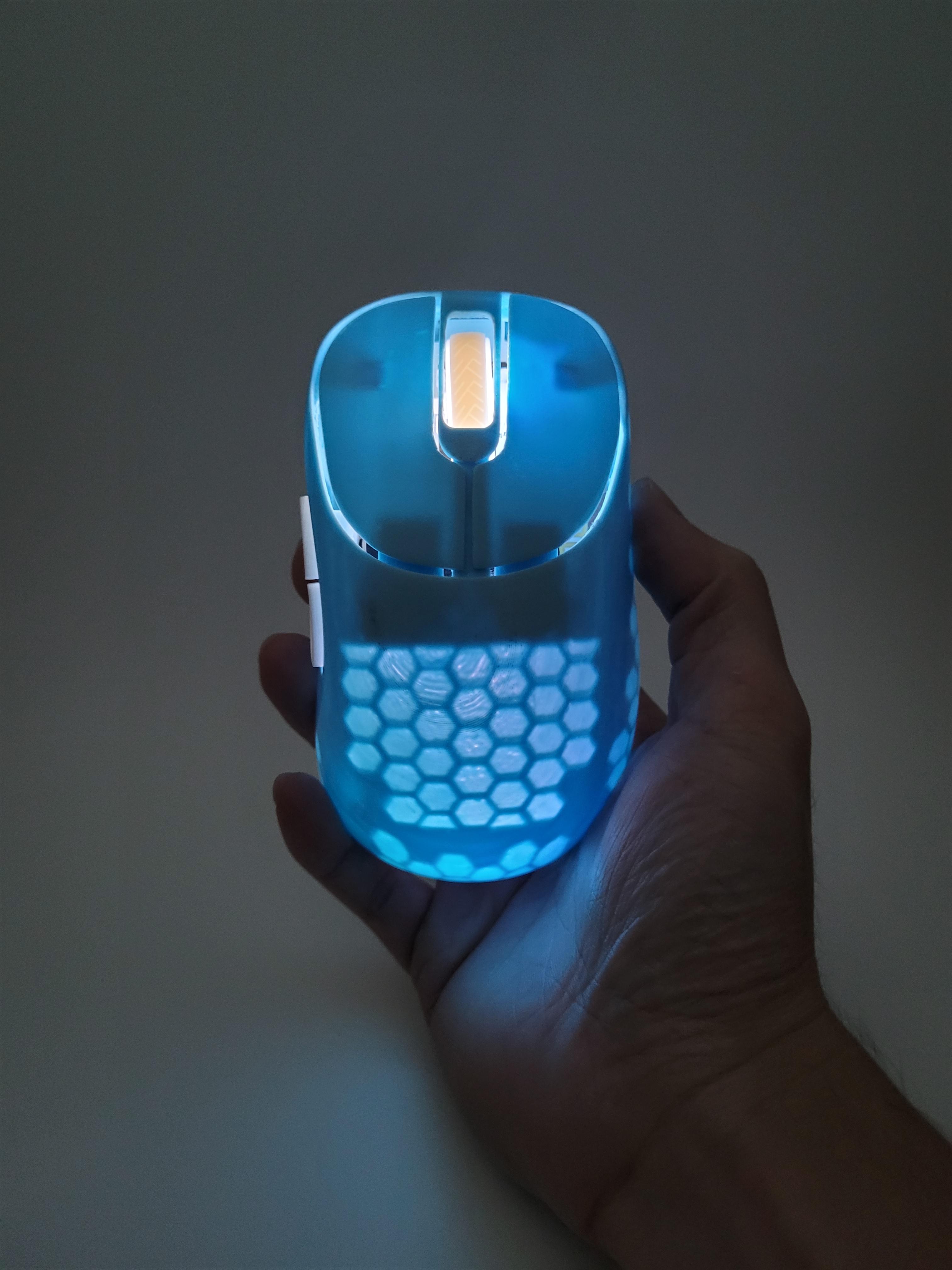
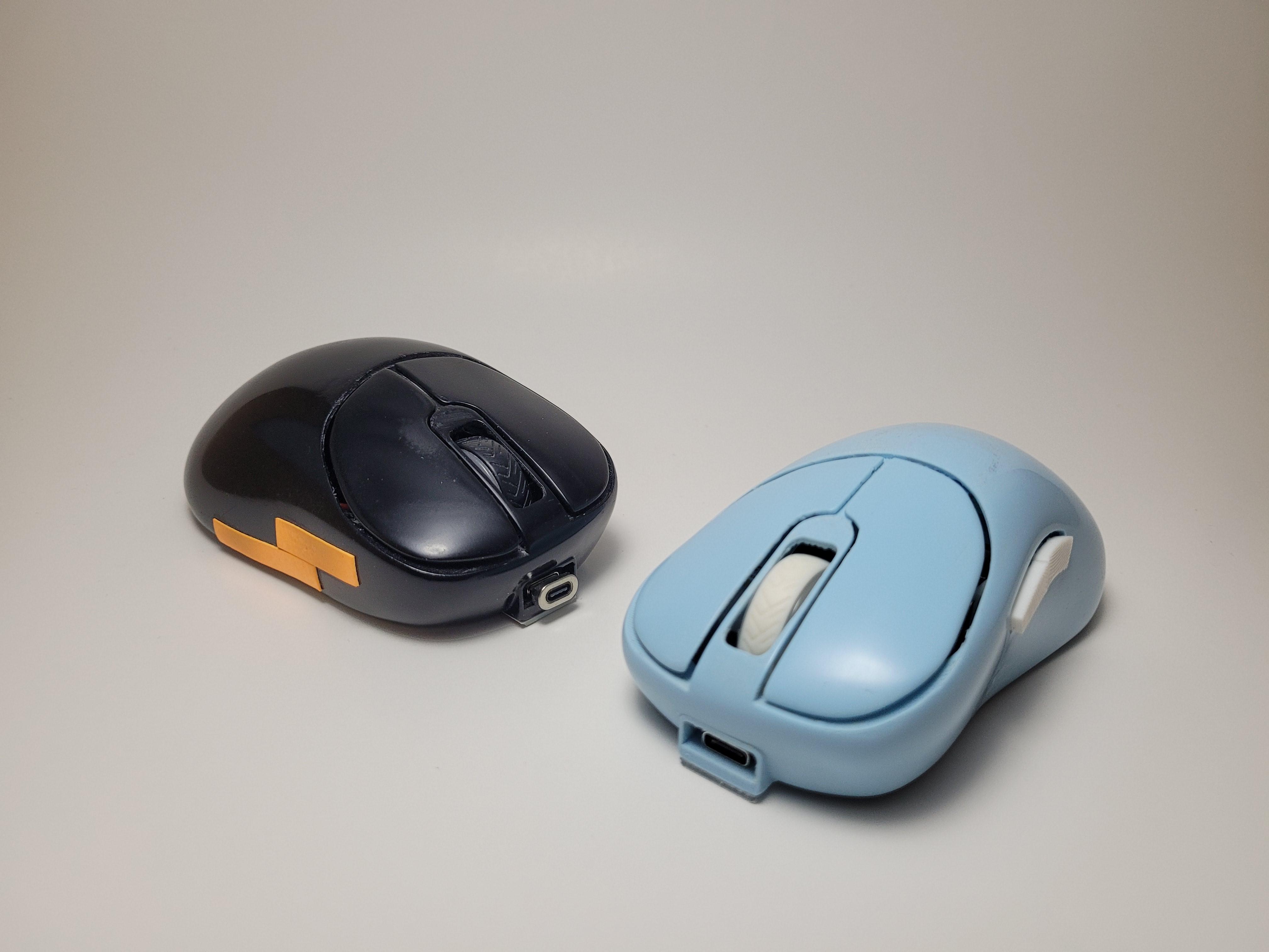
This mouse is a 3d printed shell, using Ajazz i305 Pro hardware. The shape is inspired by Vaxee Outset AX, and is in the form of an ergonomic shape gaming mouse.
If you have a spare Ajazz i305 Pro that you want to try experimenting with, this is a perfect project!
If not, the mouse can be acquired for a decent price and the overall cost of the project is reasonable
Cost Breakdown:
- Ajazz i305 Pro ($30 USD)
- 3D printed parts (~$5 USD of material)
- 3D print files fee ($6 USD)
- Screws (~$1)
- Mouse feet (~$ optional)
Total = ~$42 USD
Link: 3D Print Files
Ajazz i305 Pro Software: Drivers
Notes:
- This is not a 1:1 shape, but a reference shape was used to produce a similar shape
- No soldering is required, but if you have access to one, it will be useful for additional modding (e.g weight reduction, swapping mouse switches and scroll wheel encoder)
- Will require access to a 3d printer or 3d printing service
- 3D printed files for a small fee
- Final weight is roughly 70-73 grams (PLA Material)
- weight reduction can come to around 65-68 grams
Supplies
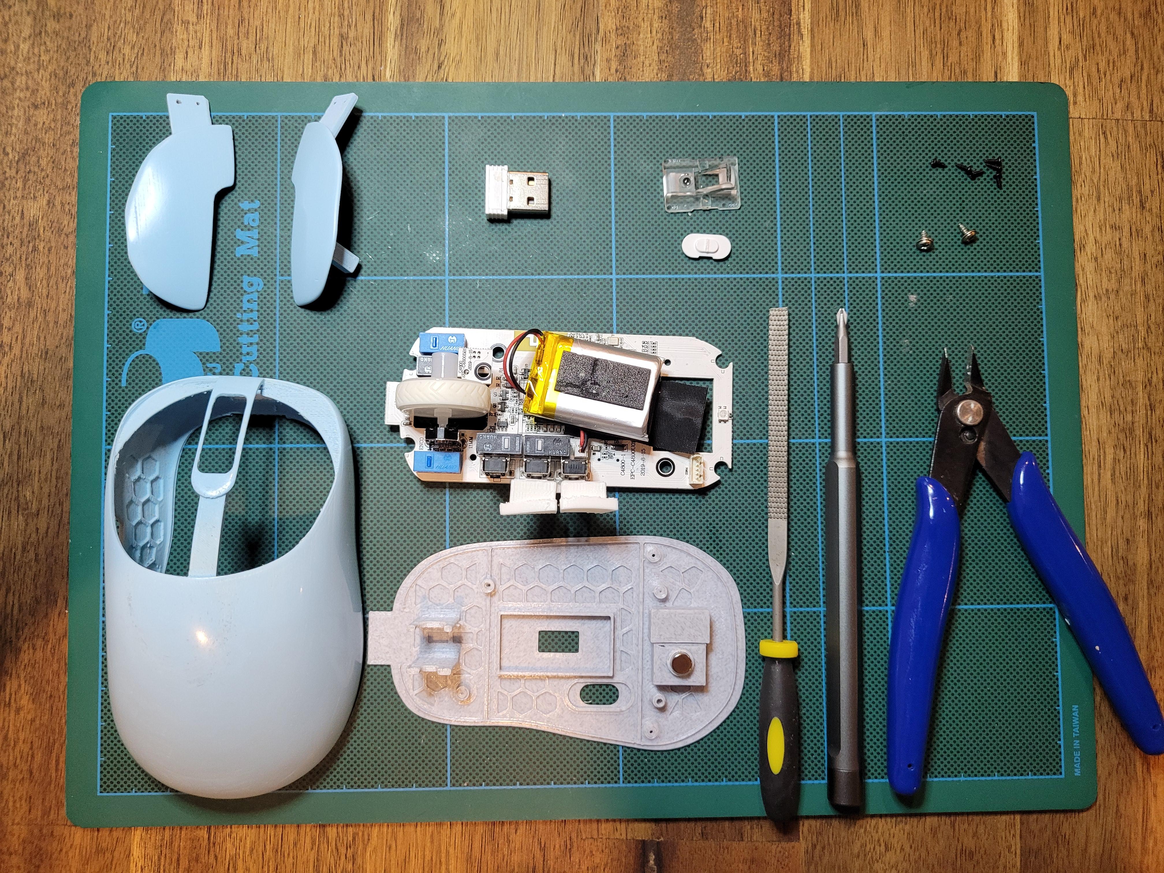
Required Parts:
- 3D Printed Mouse Parts
- Ajazz i305 Pro
- Salvage the following parts
- PCB + Battery + 2x PCB screws
- On/Off switch
- Sensor Lens
- Mouse Feet
- Magnet for Dongle (Optional)
- 3rd party Mouse Feet (Optional by recommended)
- 6x M1.2x4mm screws
Tools:
- Sand paper (~Optional)
- 120 grit, 200, 320, 600,1000, 1500, 2000
- Filers
- Glue Gun
- Some sort of clippers
- Screw driver kit
3D Print the Files
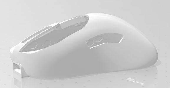
3D files to be printed:
- Mouse top shell
- Mouse bottom plate
- If you plan on using Vaxee shape mouse feet, it may block the magnetic dongle holder
- Options
- with dongle
- without dongle
- Mouse Left/Right buttons
- Mouse Side buttons
FDM print settings:
- < 20% infill settings
- Printed with tree support for top shell laying flat
If you wish, you can sand your parts now if you are confident but I would highly recommend sanding after you have testing the assembly of the mouse and fittings
Steps for sanding:
- Start with a grit no less than 120 and sand until the layer lines are no longer visible
- Work to the next grit 200
- At 320 and above, begin to wet sand the parts
- Stop at 2000
- (OPTIONAL) if you wish to have a shiny polished finish, you can apply automotive polishers. I personally used Meguiar's Ultimate Compound
If you wish to spray paint, I would not recommend sanding any higher than 600 grit. I am not an expert in post processing and spray painting, but if you want more guidance, feel free to send me a message
Disassemble the Mouse
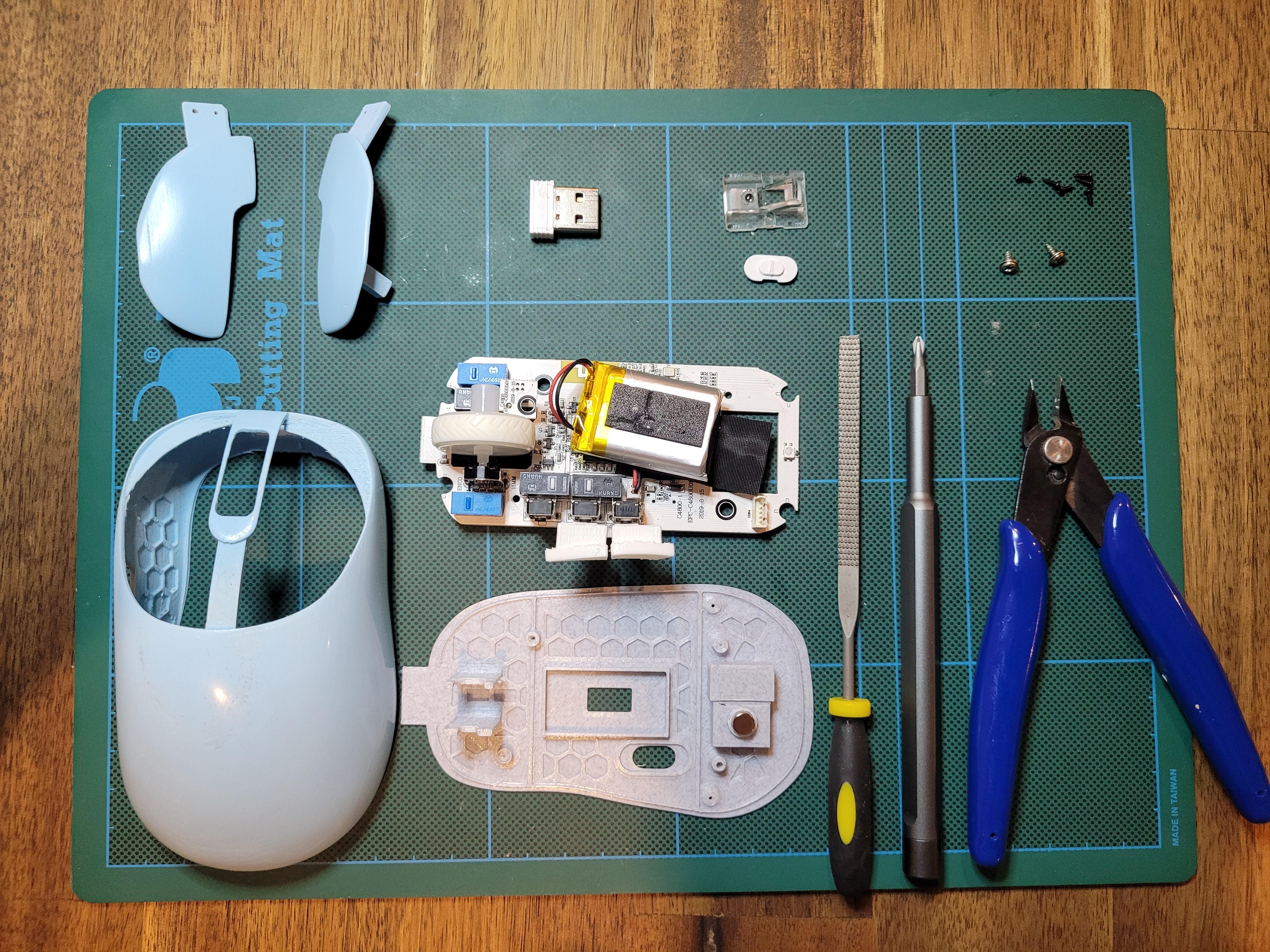
Disassemble the Ajazz i305 Pro mouse:
- Heat up the mouse feet on the bottom and CAREFULLY peel the mouse feet off. If you bend or damage the mouse feet while removing, it will be hard to reuse as it will not stick flat back onto any surface. But if you do not care, skip to step 3
- Stored the mouse feet aside and try not to get any dust stuck to it
- Remove the bottom screws and salvage the following parts:
- PCB + Battery + 2x PCB screws
- On/Off switch
- Sensor Lens
- Magnet for Dongle (Optional)
Clip the On/off Switch
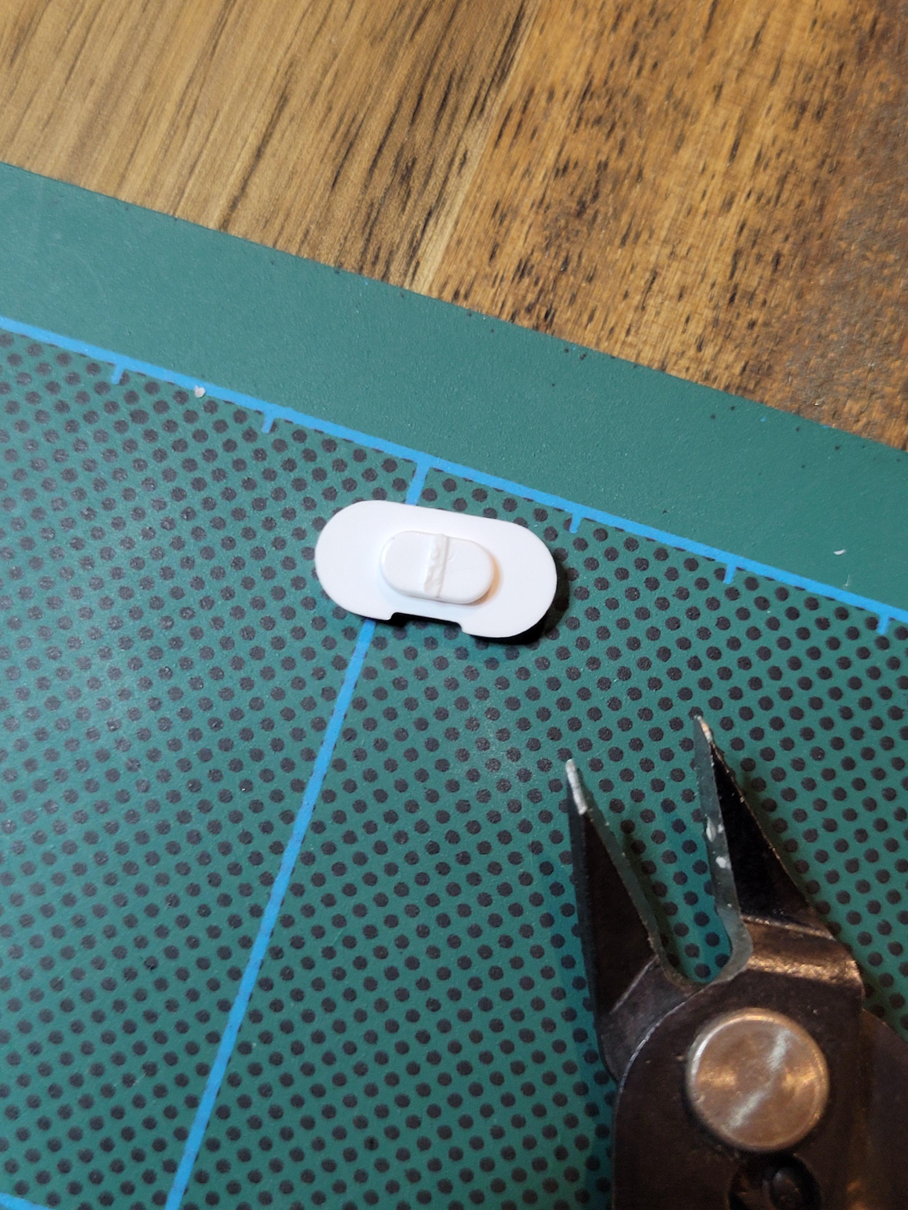
Using your clipper, clip off the middle groove. This will prevent the switch from being extruded too far out the bottom
Bottom Plate Assembly
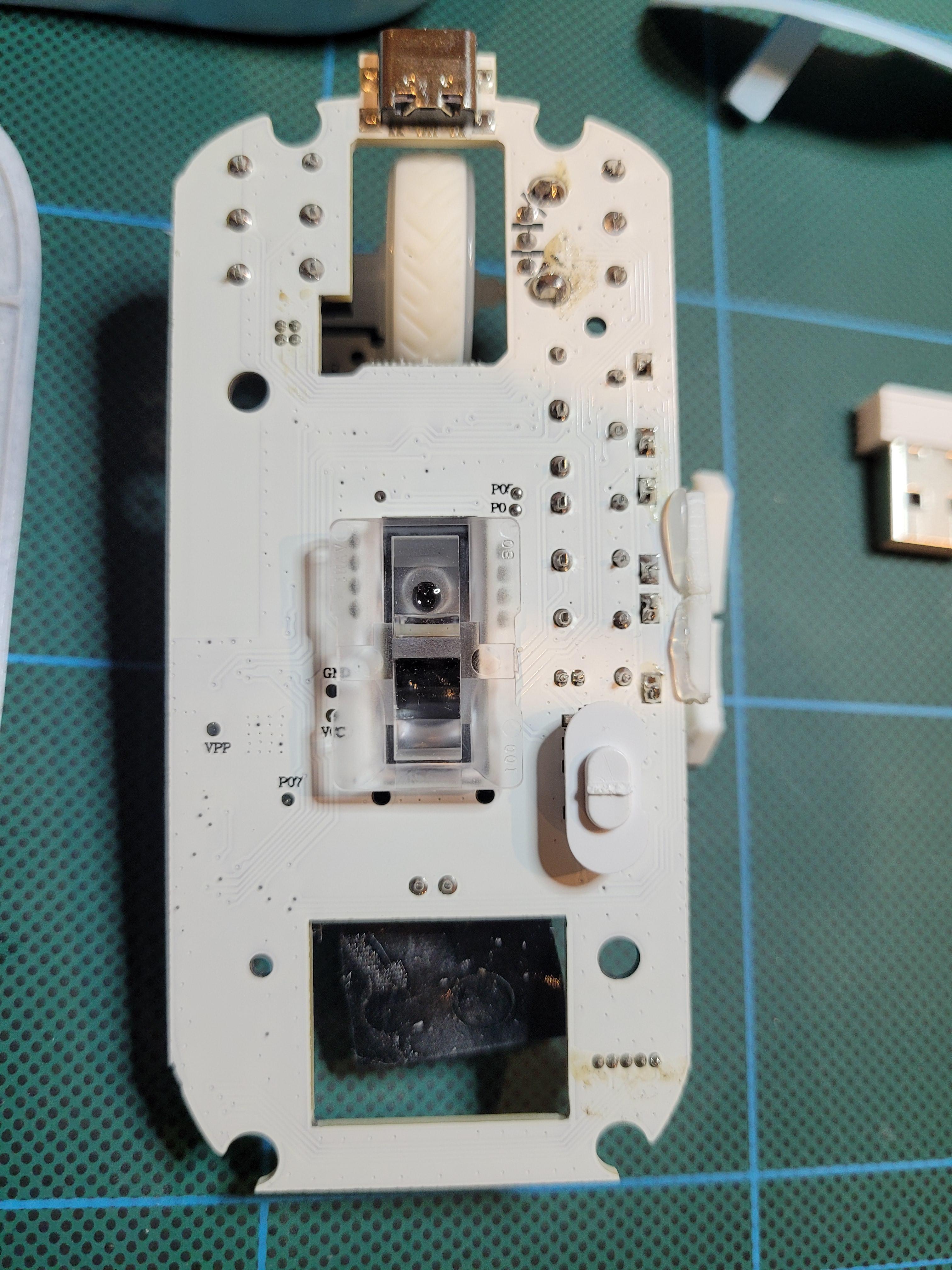
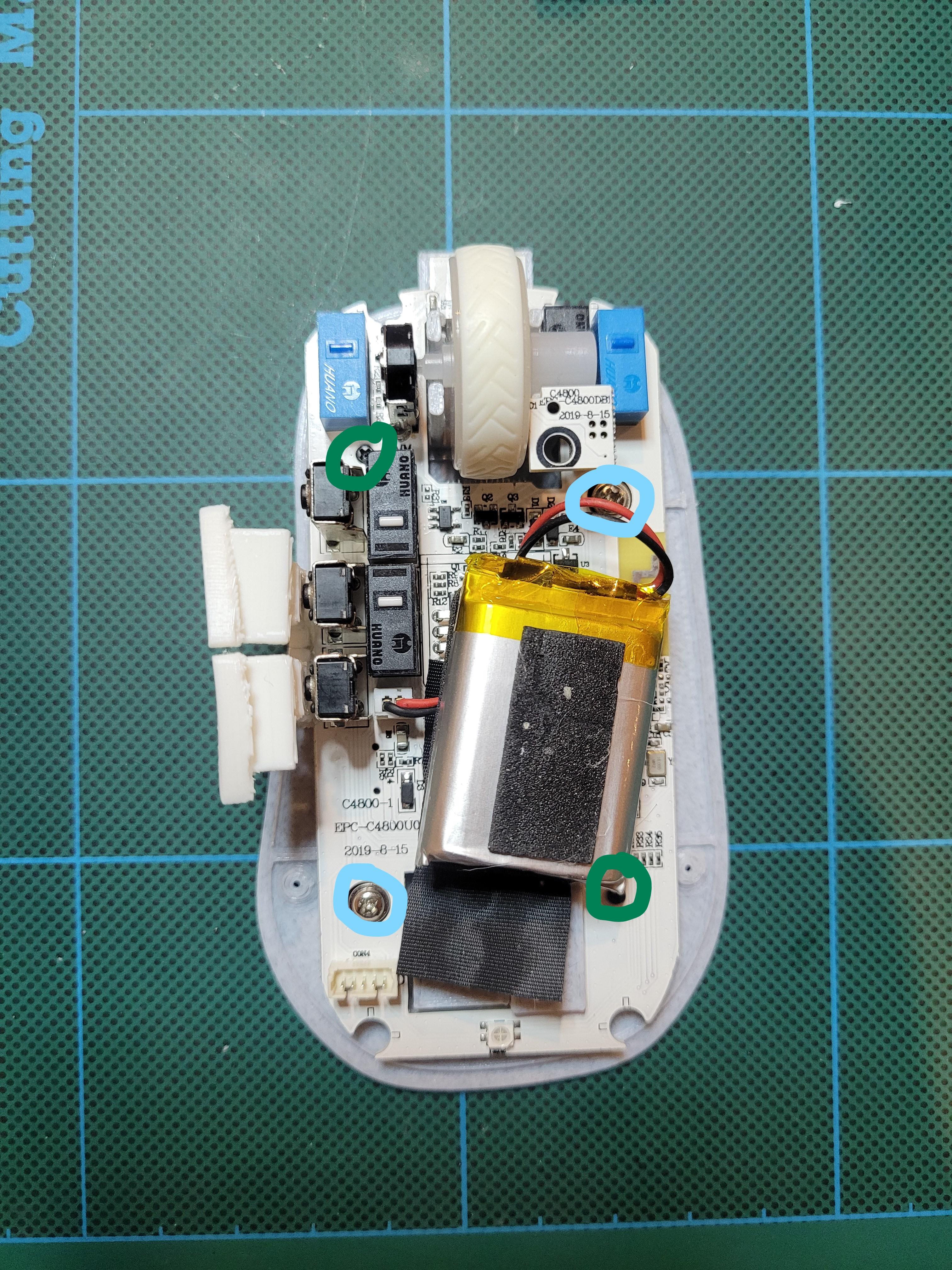
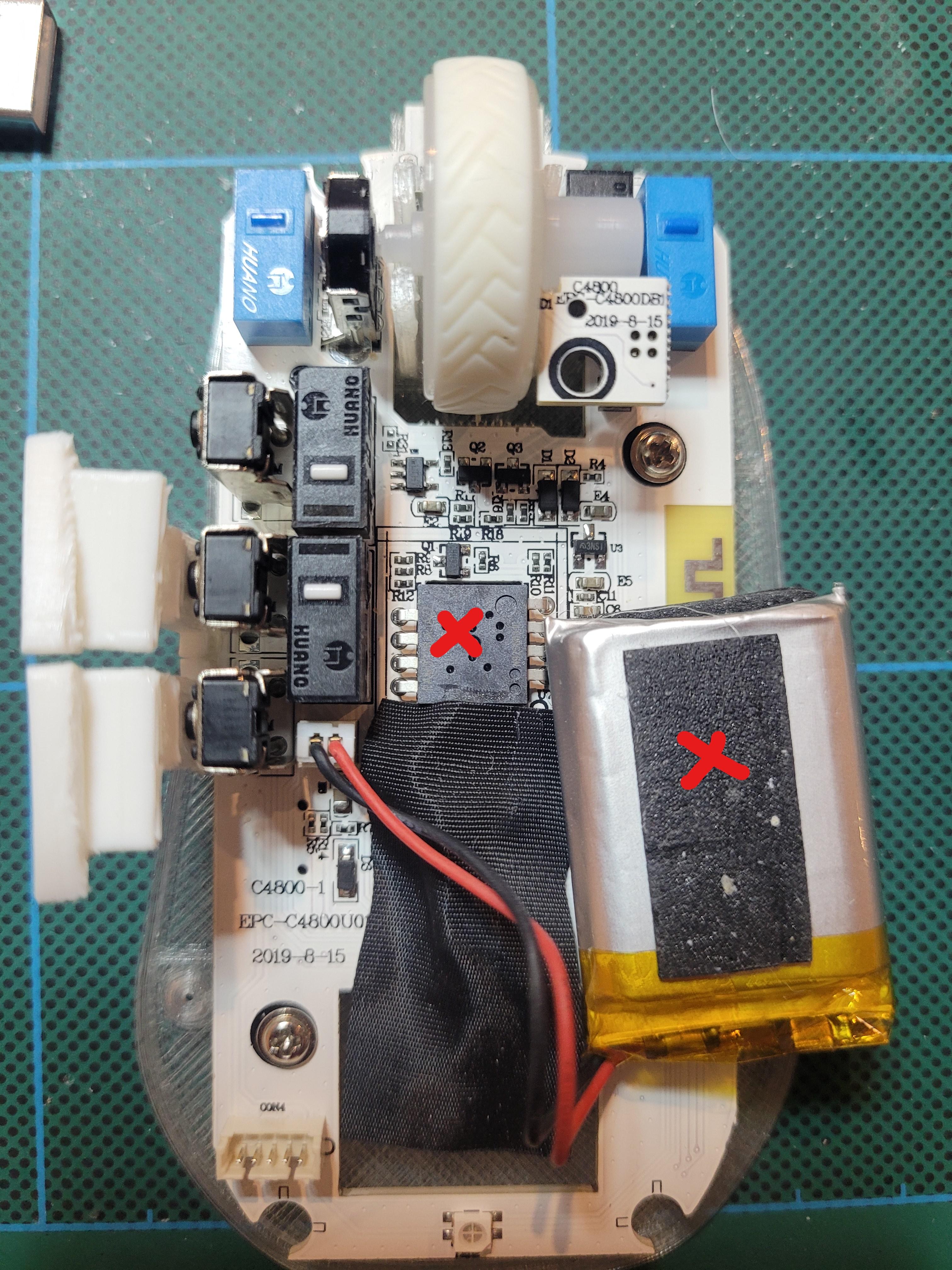
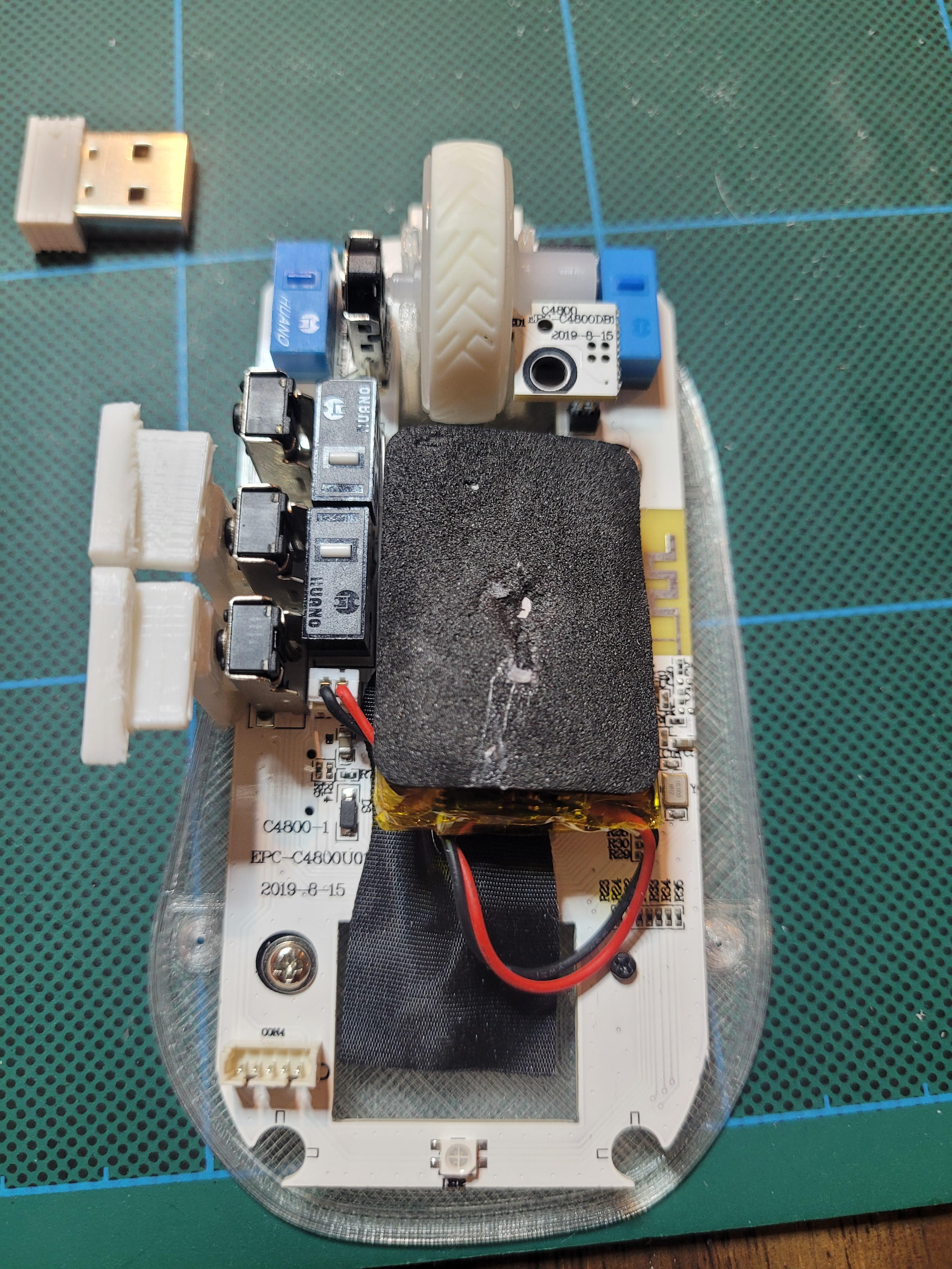
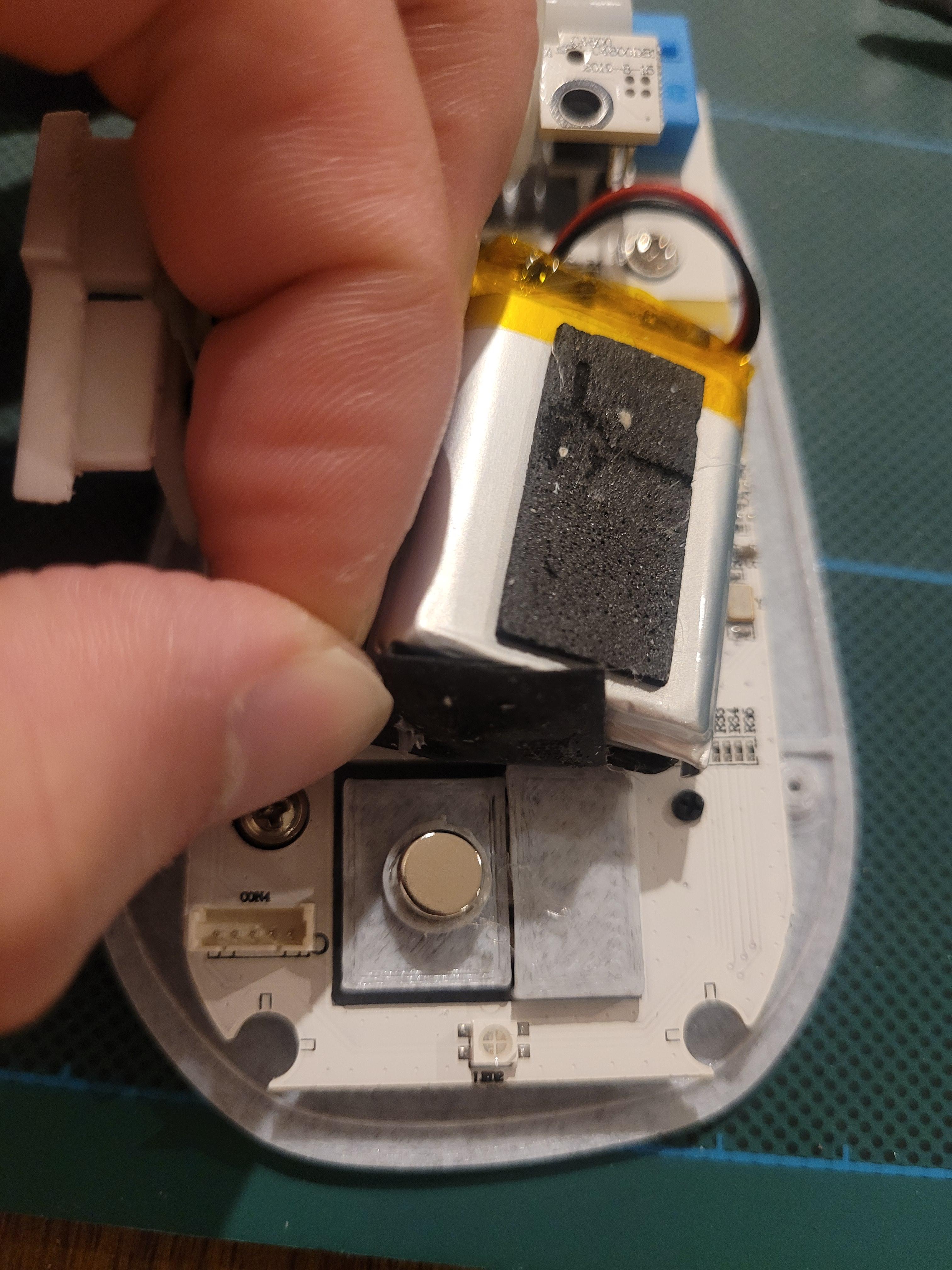
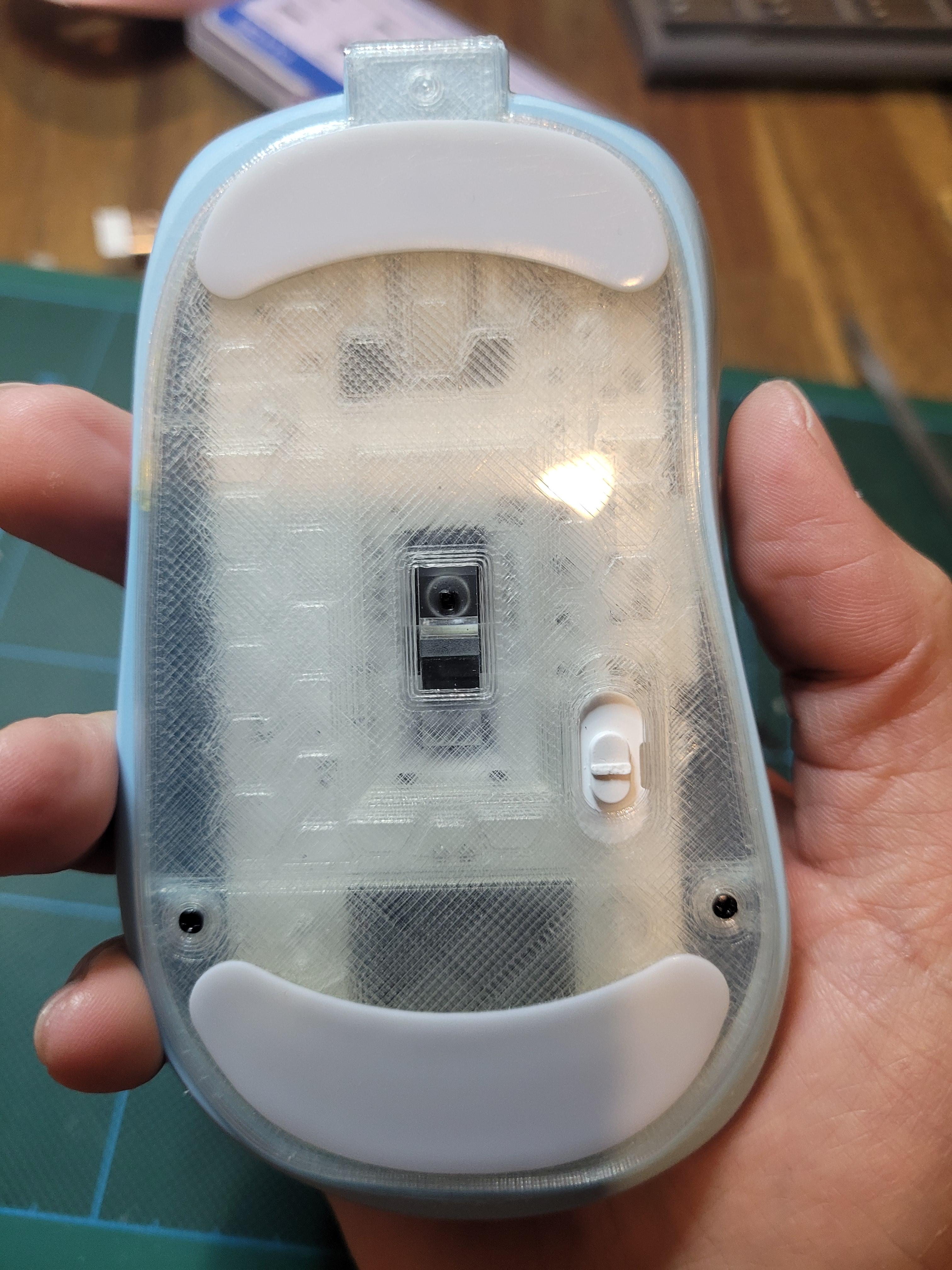
- Mount the bottom sensor lens and On/Off switch to the bottom of the PCB. I find it a lot easier if you keep the PCB upside down while placing onto the bottom plate
- Use 2 of the PCB screws that came with the mouse and 2x M1.2x4mm screws to mount the PCB
- refer to the image
- green holes are for the M1.2x4mm
- teal holes are for the PCB screws
- Apply some glue gun to the red marks (refer to image) and stick the battery accordingly to the pcb
- (OPTIONAL) For the dongle bottom plate, apply some glue gun as well to hold the magnet
Side Buttons
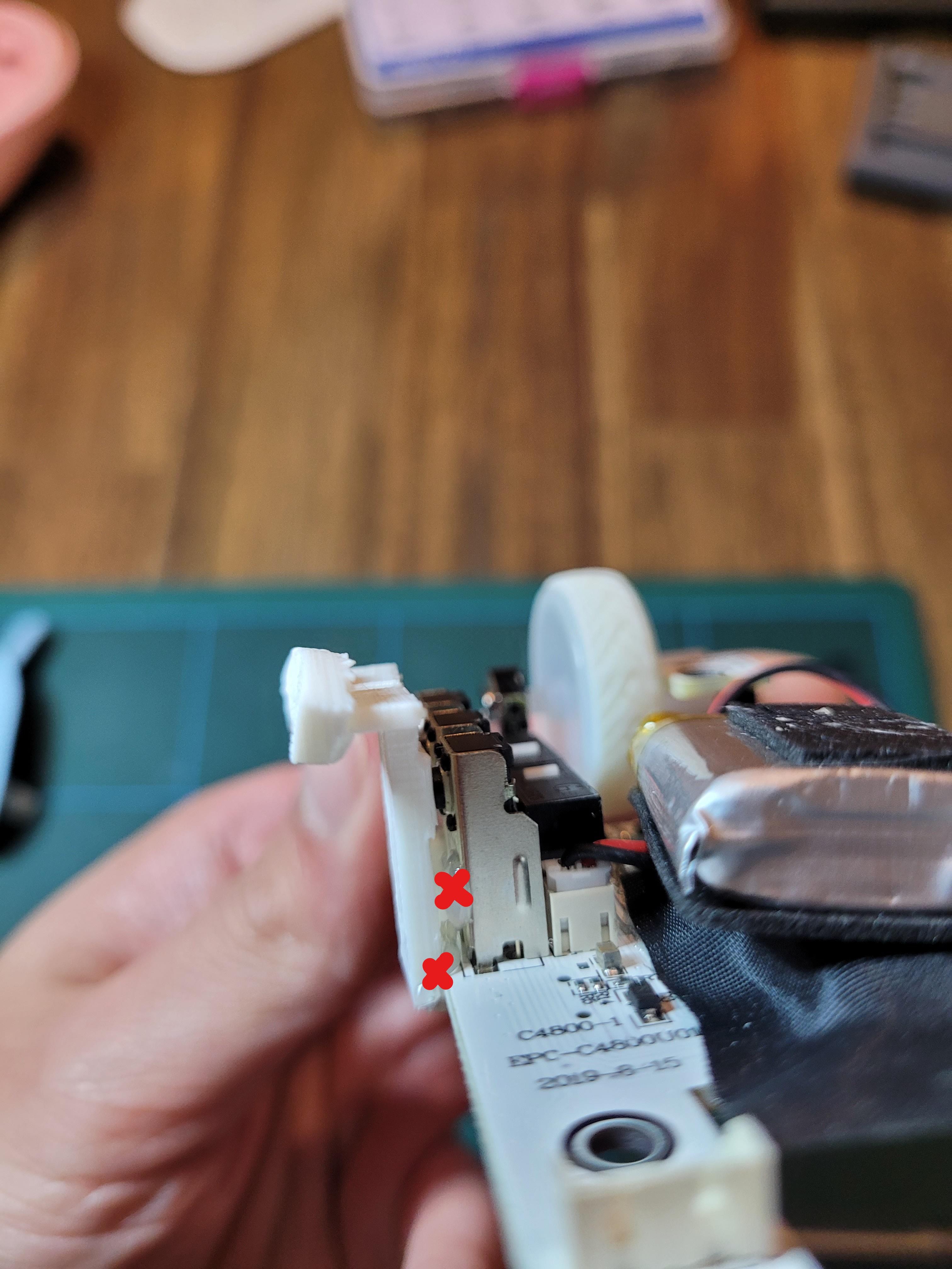
Apply some glue gun to the spots for the side button to mount onto the PCB and side switches
Top Shell and Left/Right Mouse Buttons
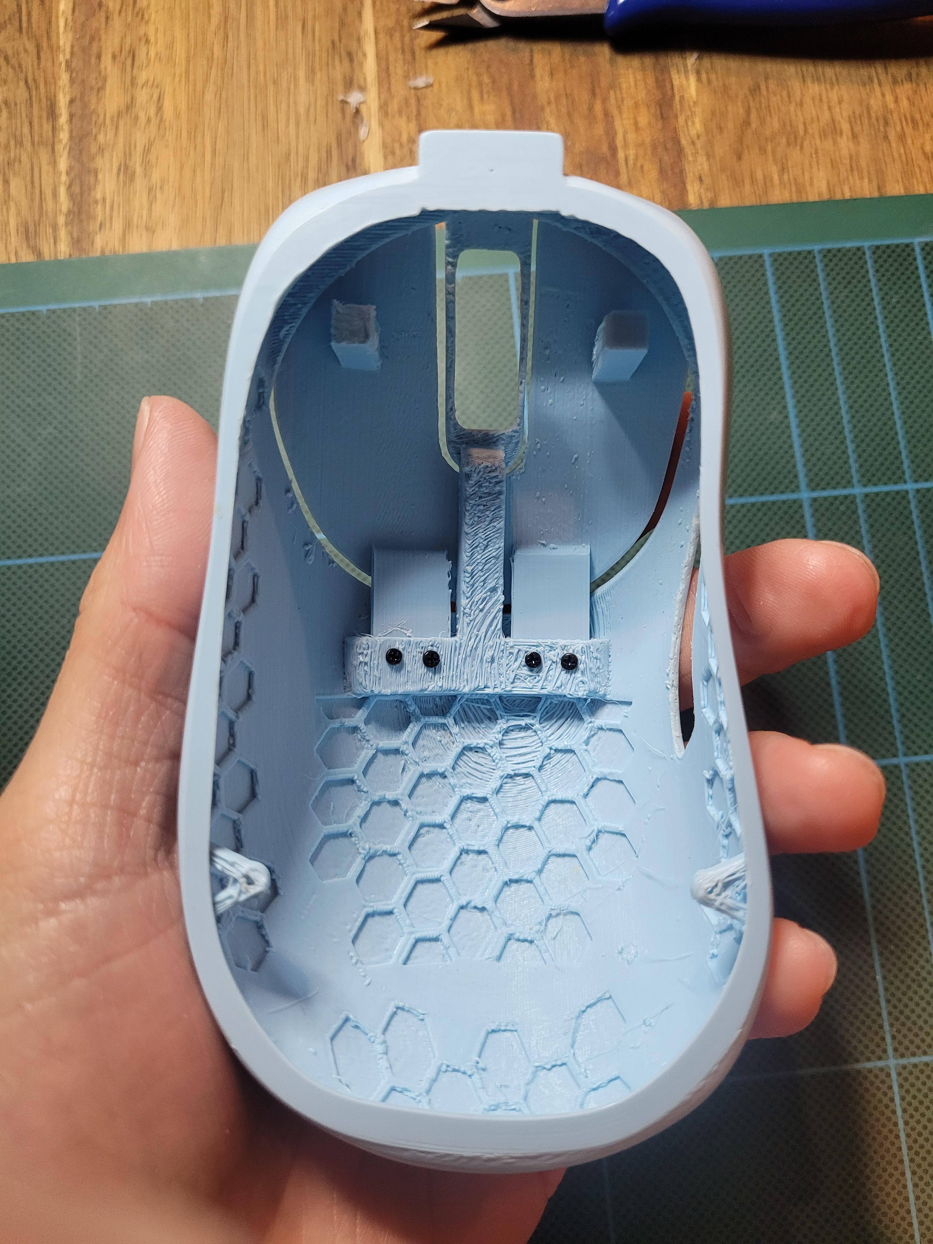.jpg)
- Insert Left/Right Mouse buttons into the Top Shell slots
- Use the 4 screws (M1.2x4) to secure the buttons
Note: Because these are 3d printed parts, the screw holes produced may not be the best. Use existing screws or something sharp (tweezers) to predrill the holes to make it easier when screwing the mouse buttons on
Top Shell and Bottom Plate Assembly
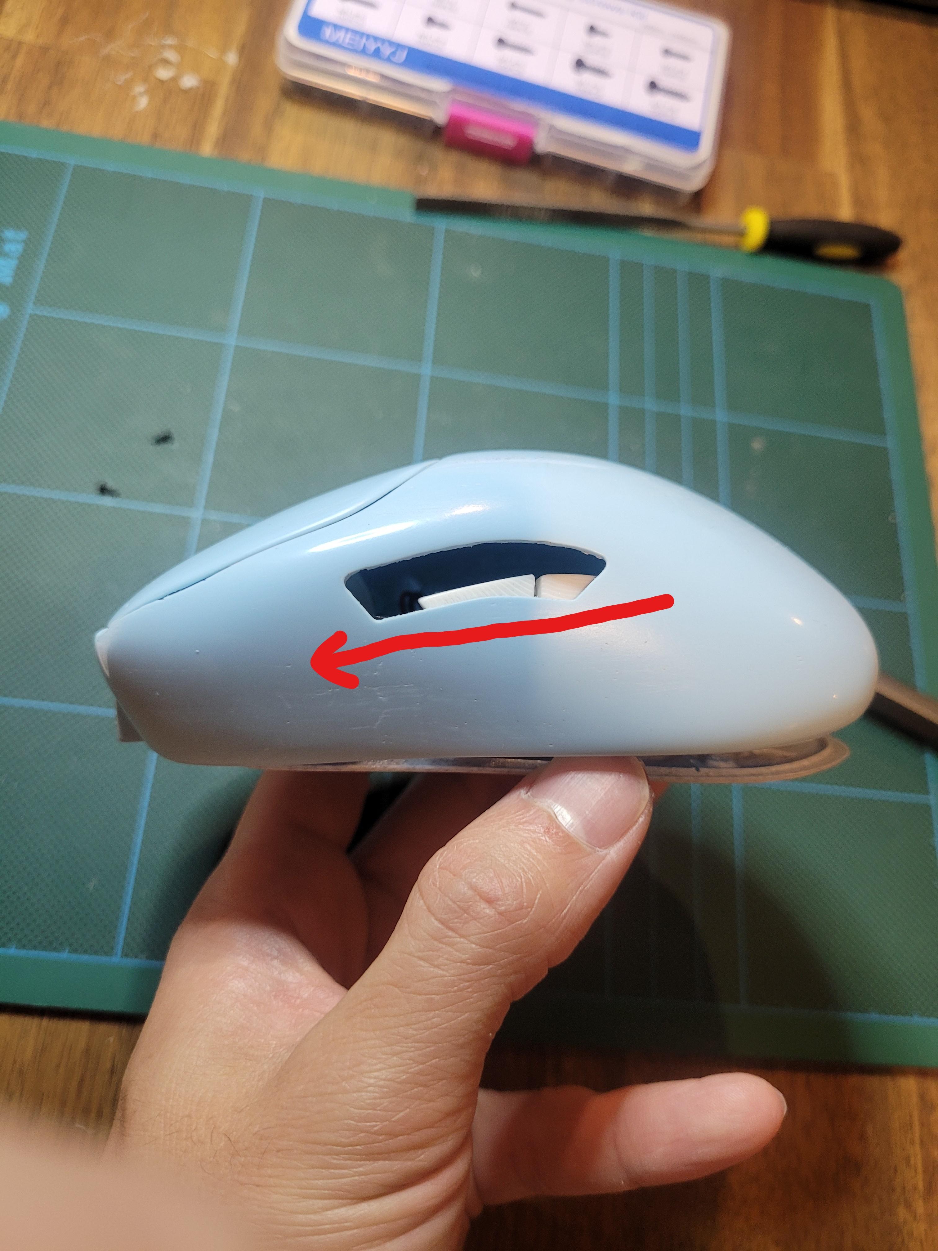
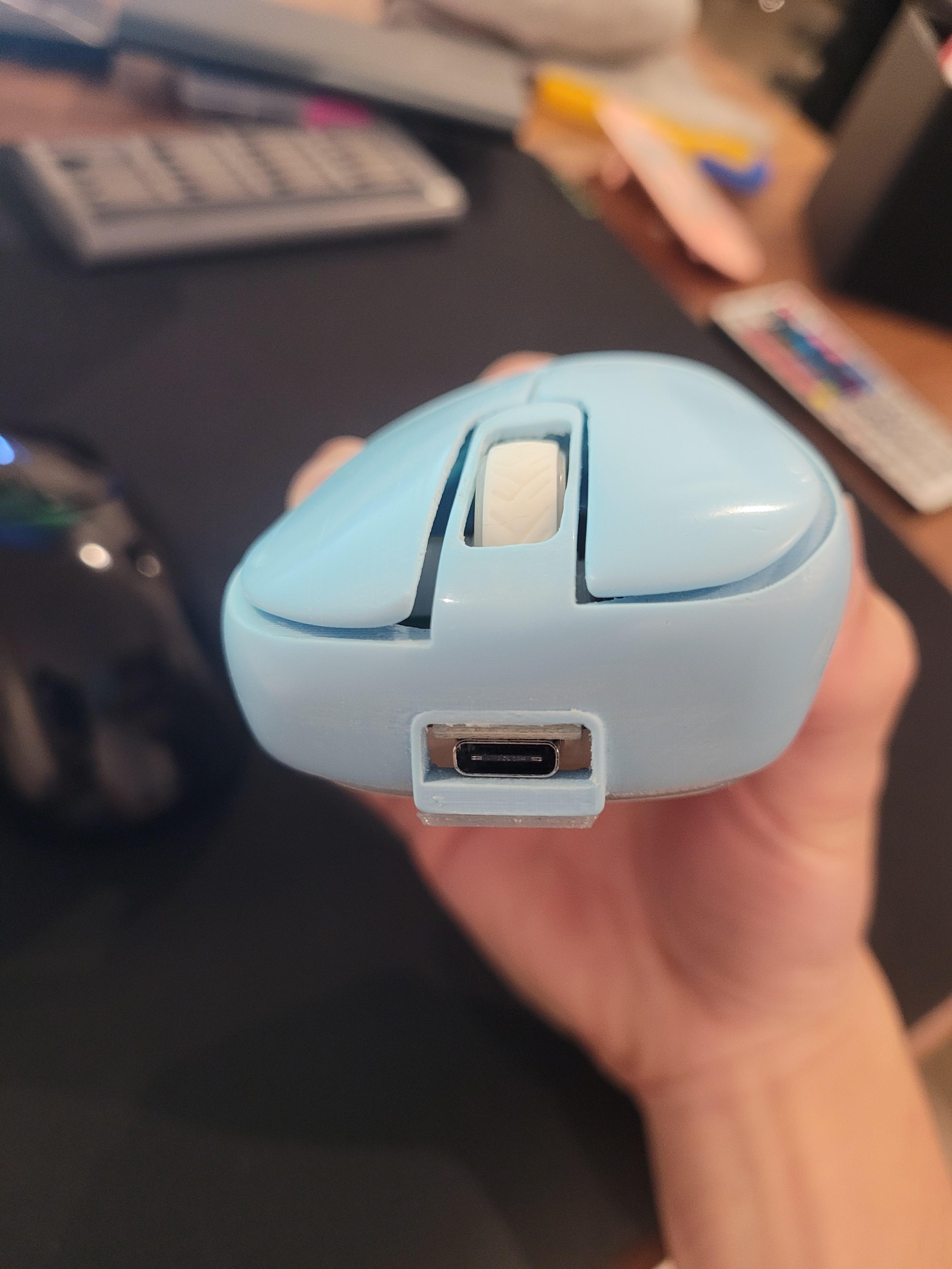
.jpg)
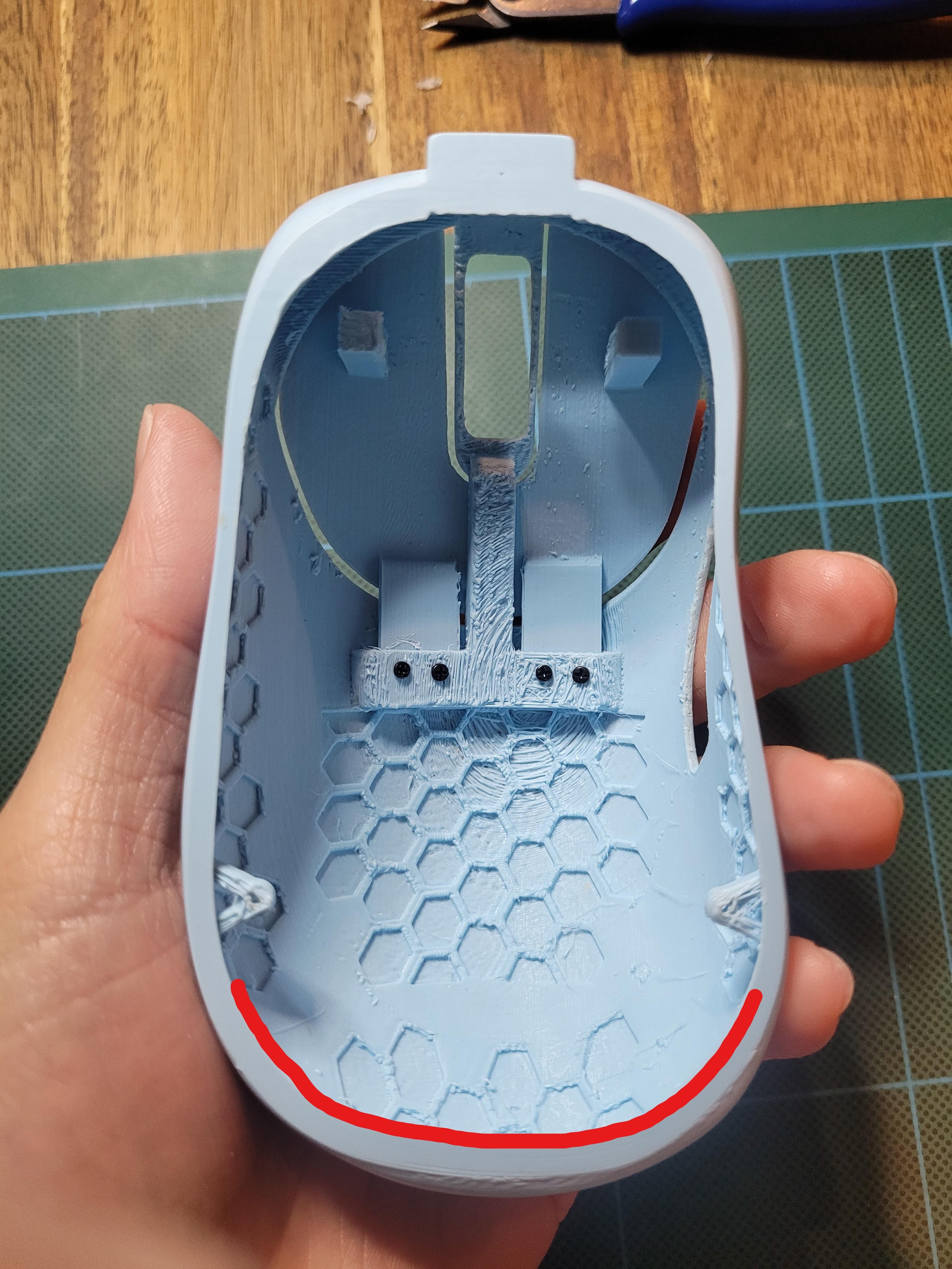
- Slide the top shell onto the bottom shell + PCB. The front goes in first at an angle where the USB C port will sit. If you find the top shell too tight to fit, sand part of the bottom hole (refer to image)
- Use two screws (M1.2x4) to secure the top shell and bottom plate together
- Apply your mouse feet to the bottom plate
Mouse Click Adjustment
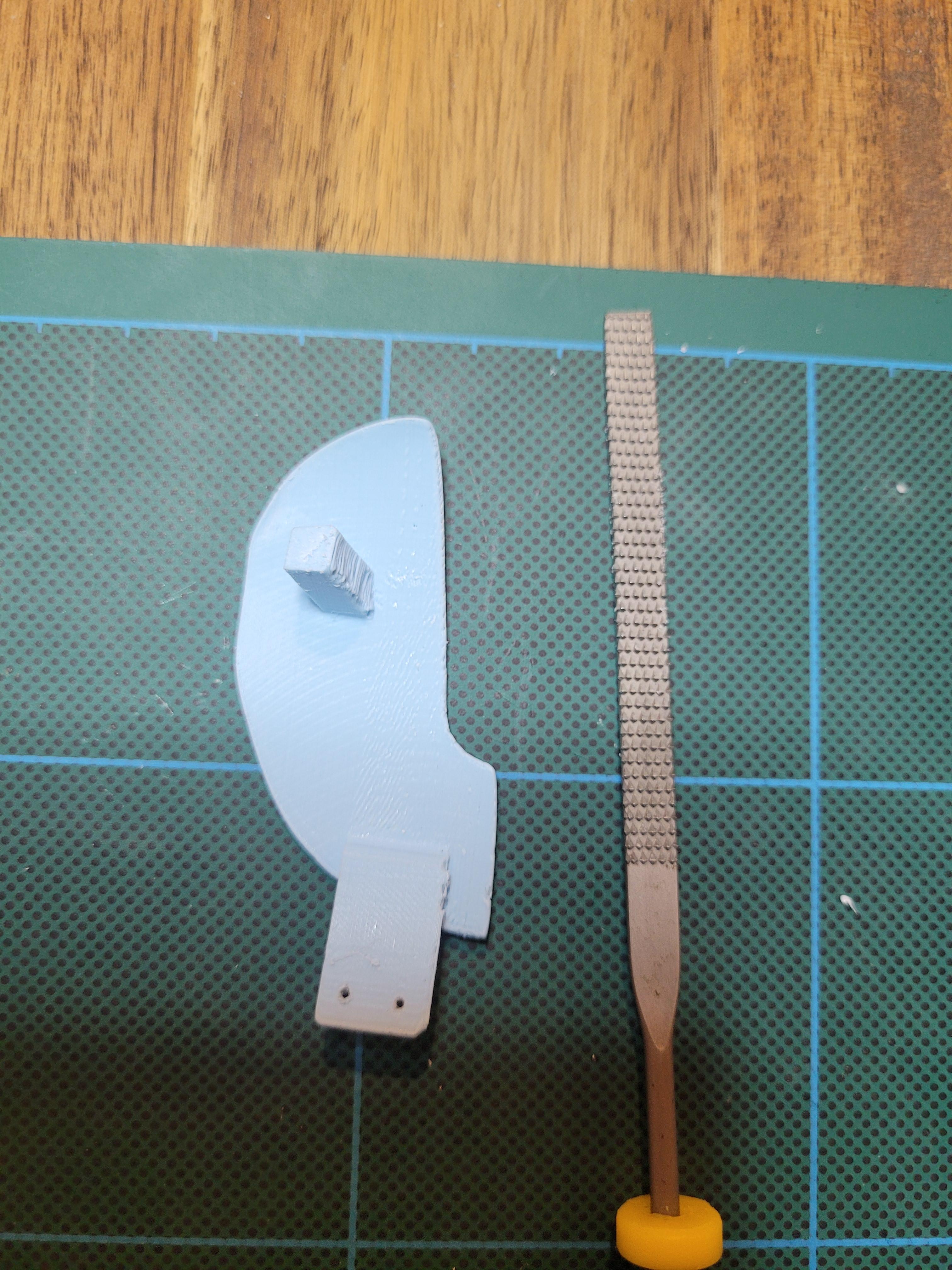
I've purposely made the Left/Right mouse stems a bit longer than needed so they can be adjusted accordingly.
After you've assembled your mouse, test your clicks and see if they are to your liking. Use your filer and SLOWLY file away the stems with micro increments. Make sure you do not file too much as you don't want the stems to be too far from the mouse switches. If you file too much, just use aluminum tape or something to fill in the gap.
Finshed!
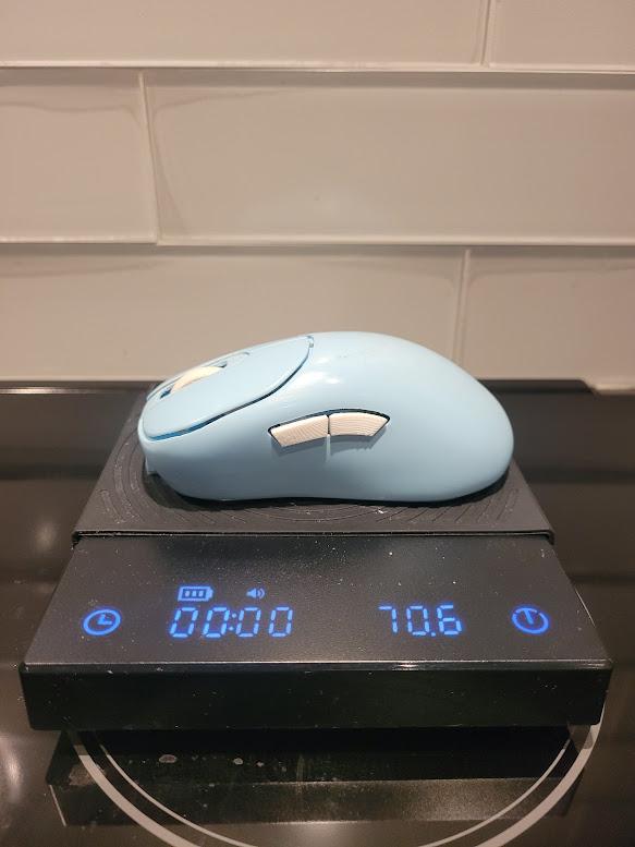
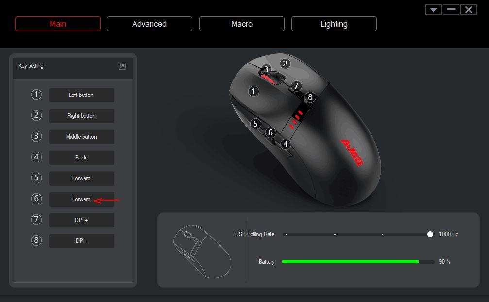
And your mouse is complete! Please adjust the software for the side buttons (mouse4/5).
Mouse Bindings:
- bind Mouse 6 as Forward
Here are some weight reduction tips:
- smaller battery (e.g 300 mah)
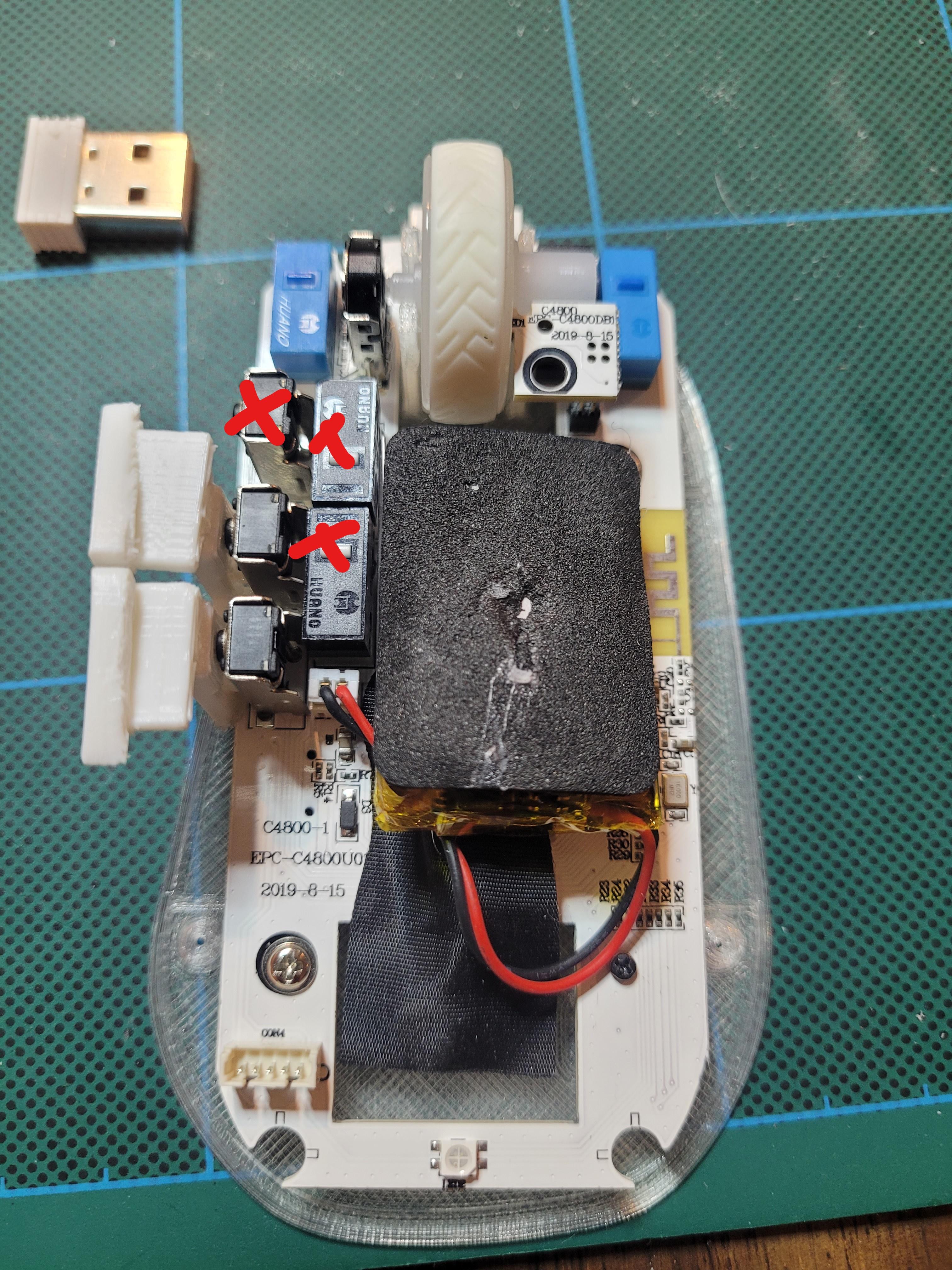
- remove dpi switches
- remove mouse 4 switch
- print the parts in ABS