3D Printed Mouse Joystick for Computer (with Right and Left Click)
by Tevendale_Engineering in Circuits > Assistive Tech
548 Views, 2 Favorites, 0 Comments
3D Printed Mouse Joystick for Computer (with Right and Left Click)
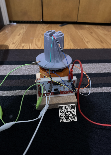
: Set-up and Overview)
This controller can replace the functions of the traditional mouse but is packed in a compact body given by a joystick. The goal is to attach this module in areas where traditional mice require a footprint larger than available, such as the armrest of a wheelchair. Additionally, the interchangeability of the grip of this device allows you to attach external accessibility parts onto it for people with conditions that prevent the use of the traditional right-handed mouse structure. As the device is wired, batteries are not required. To make the device durable and easy to produce, a majority of the device is created using 3D printing.
Supplies
Access to 3D printer and PLA filament required
Supplies/tools required:
- Copper tape
- Electrical tape
- Hot Glue
- Super glue
- Alligator clips (optional)
- Arduino Jumper Cables (8)
- Makey Makey
- Springs (6-pack)
- Sandpaper
- Pliers (for removing the 3D print infill)
Usb-a converter may be required based on your device's I/O
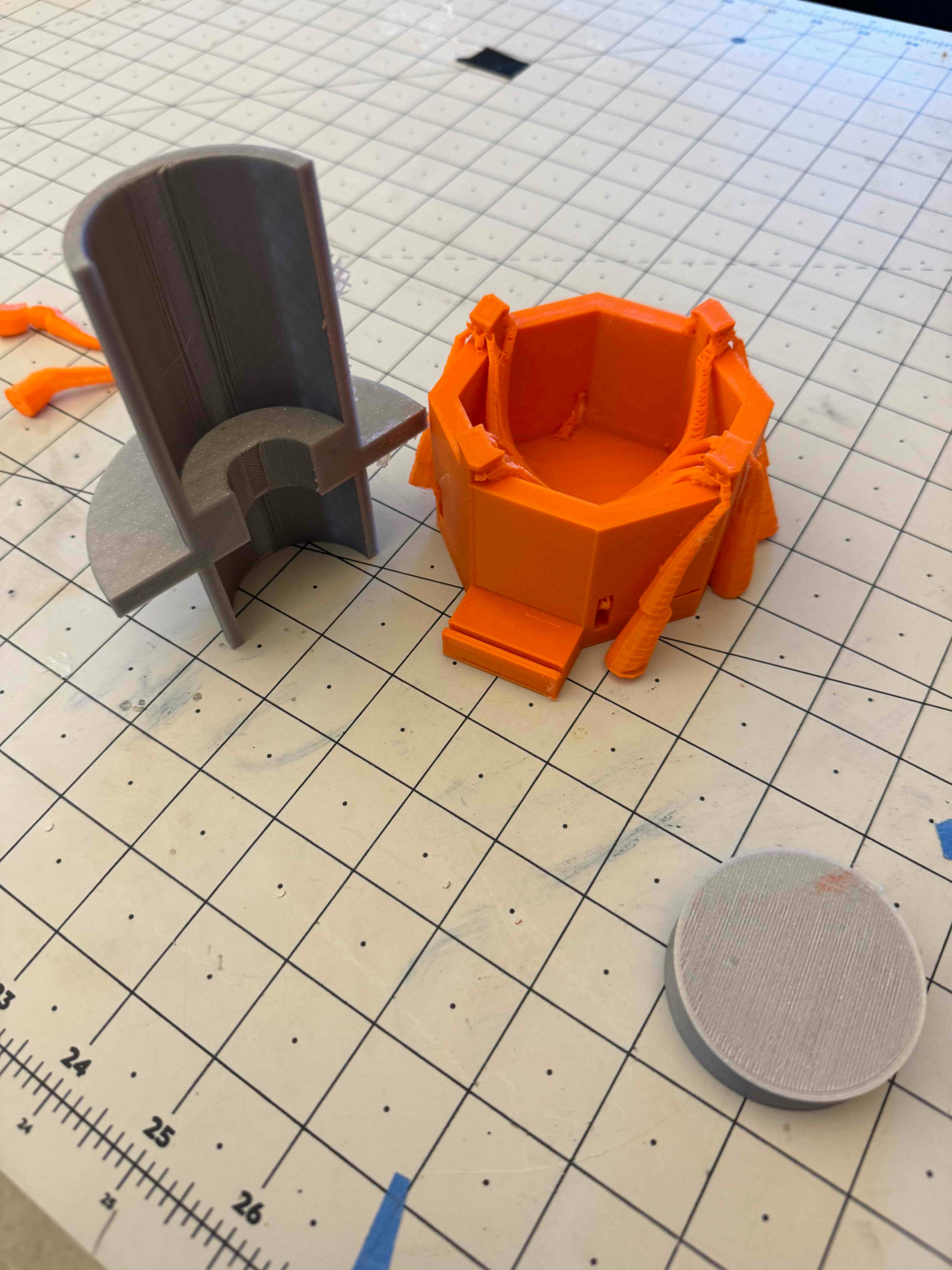
Print 3D Parts
.JPG)
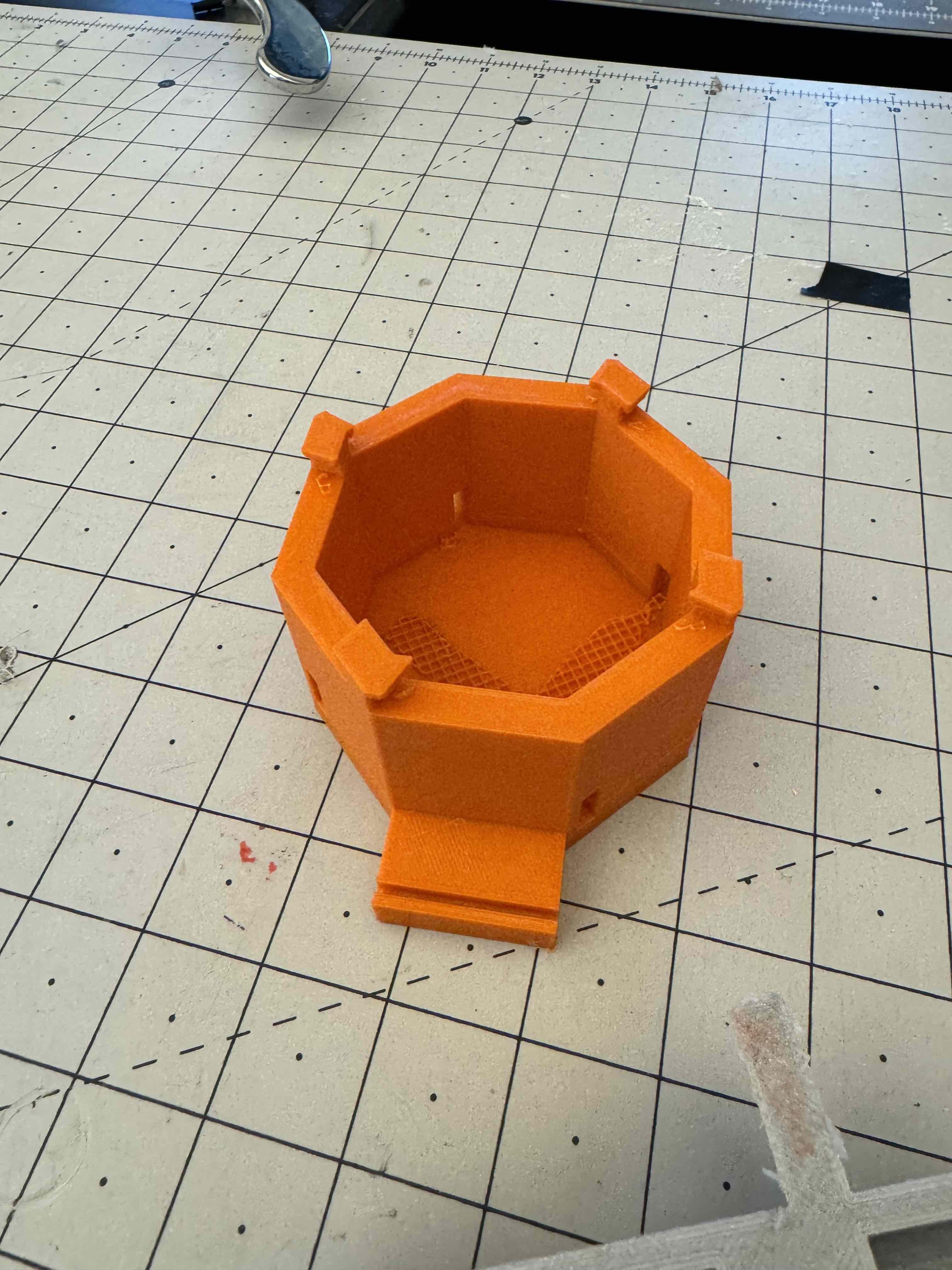
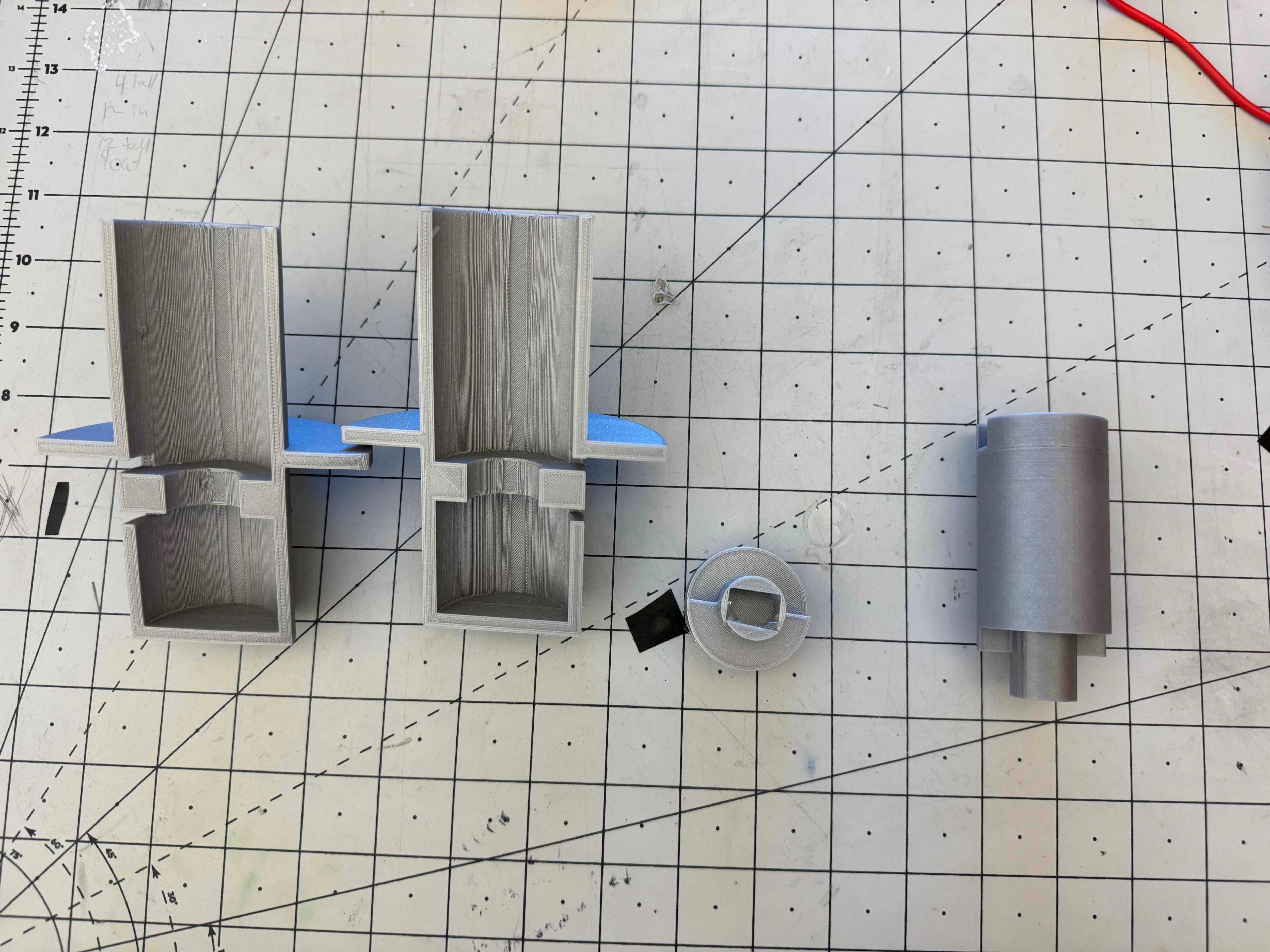
- Print these 3D prints as shown below with infills on. Some may be able to be done together in one singular print. I recommend using Ultimaker Cura to convert these files into G-Code for 3D printing purposes.
- After the prints are finished, remove any excess infill in the print with pliers.
Creating Piston Piece
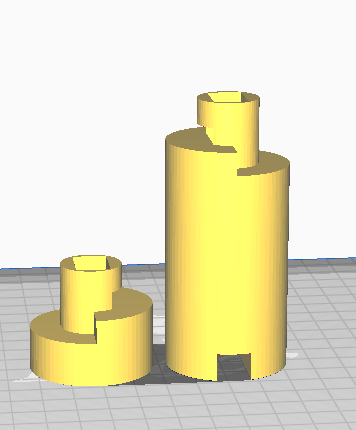
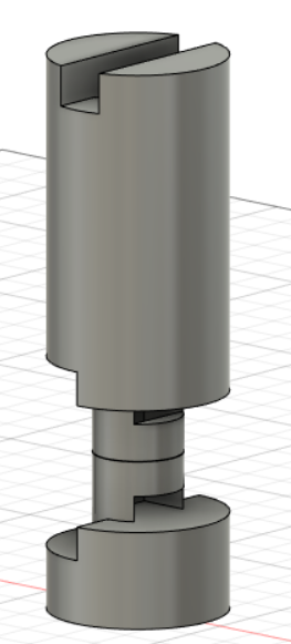
- Connect the piston piece with super glue so the end result looks like the image above.
Add Electronics to the Piston Piece
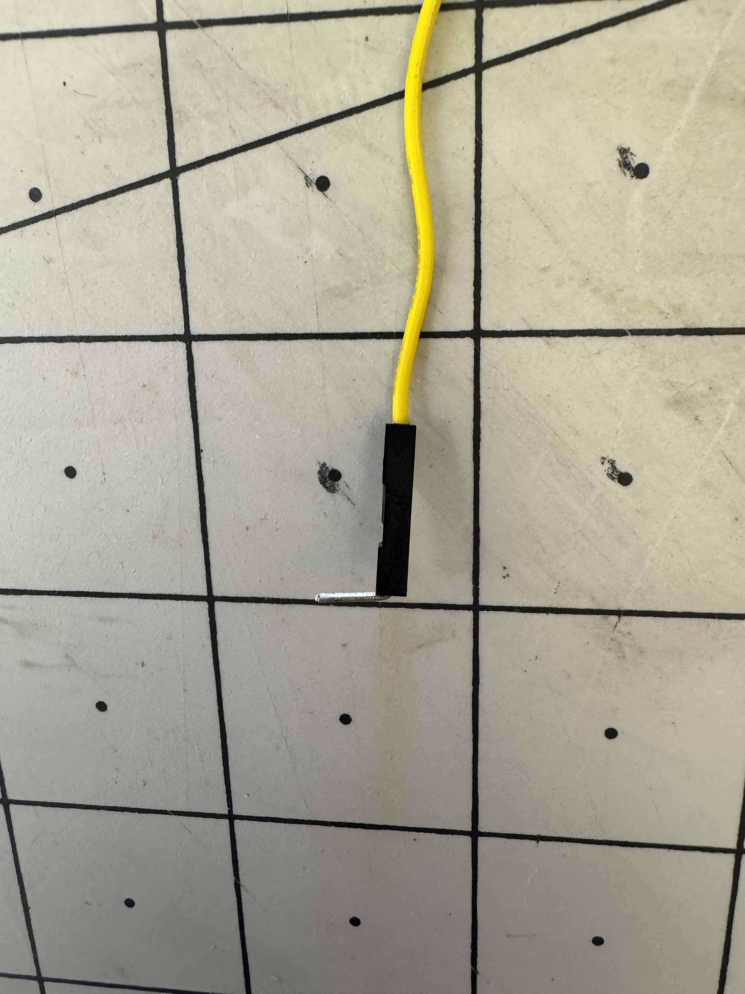
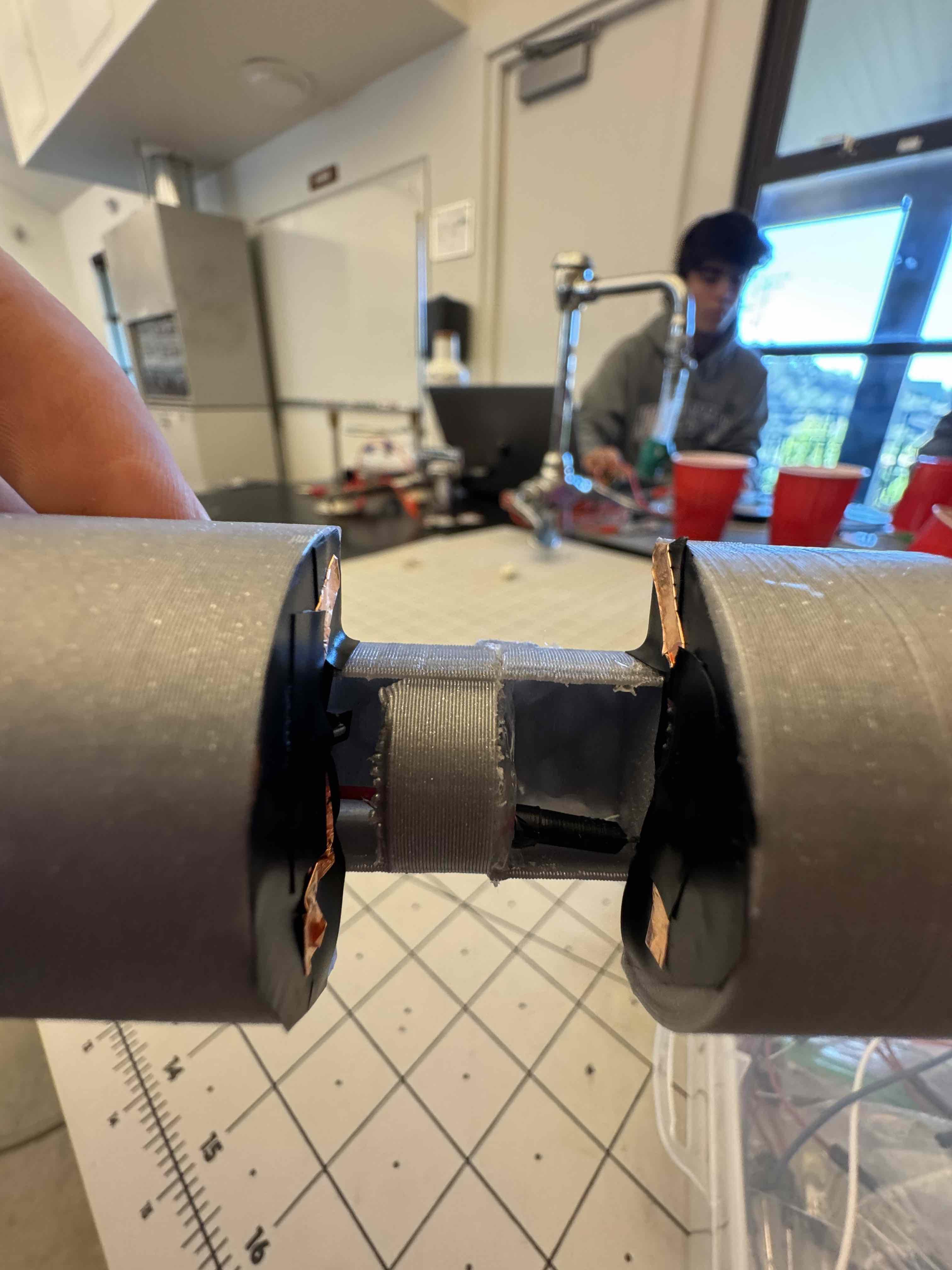
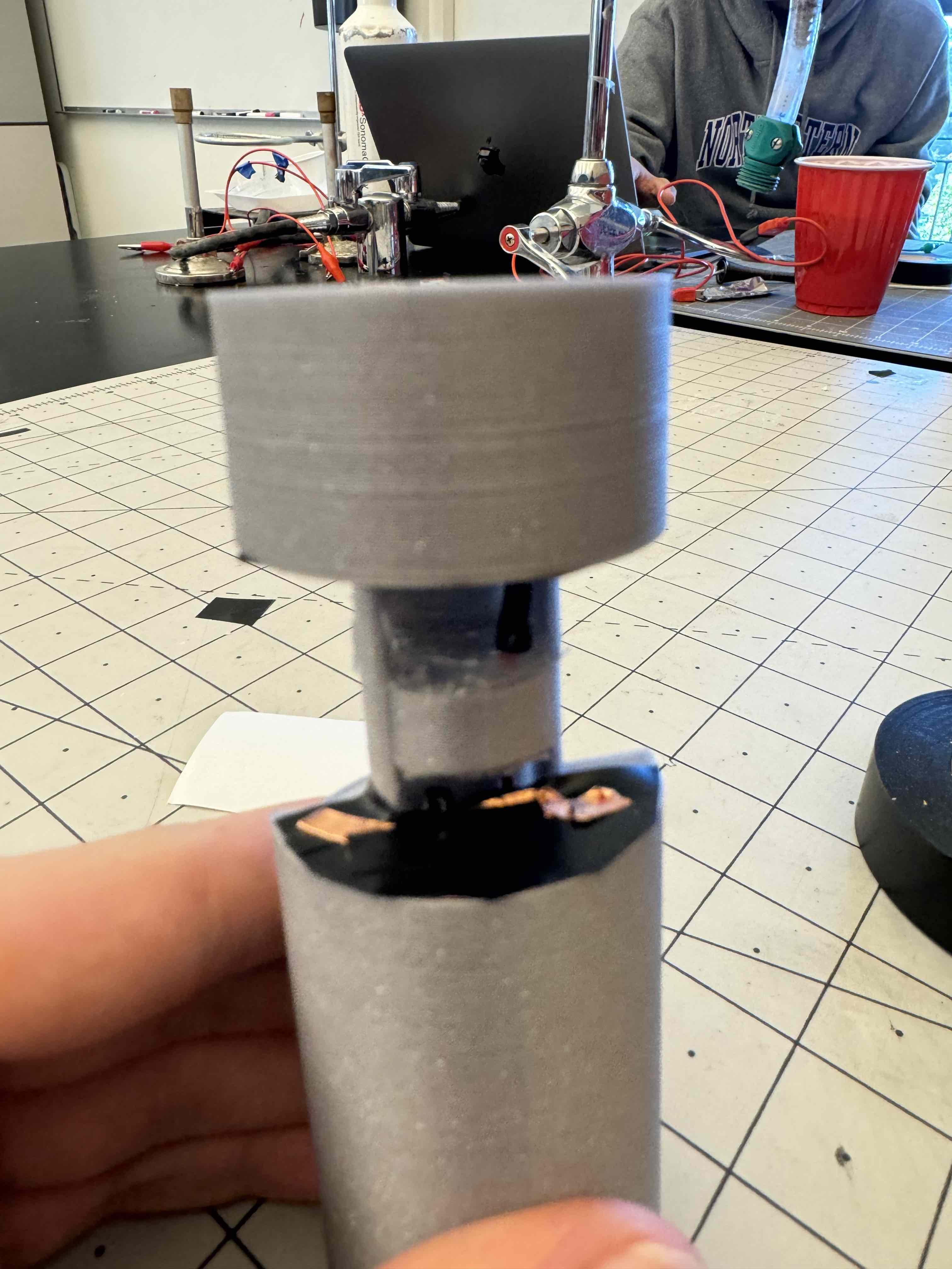
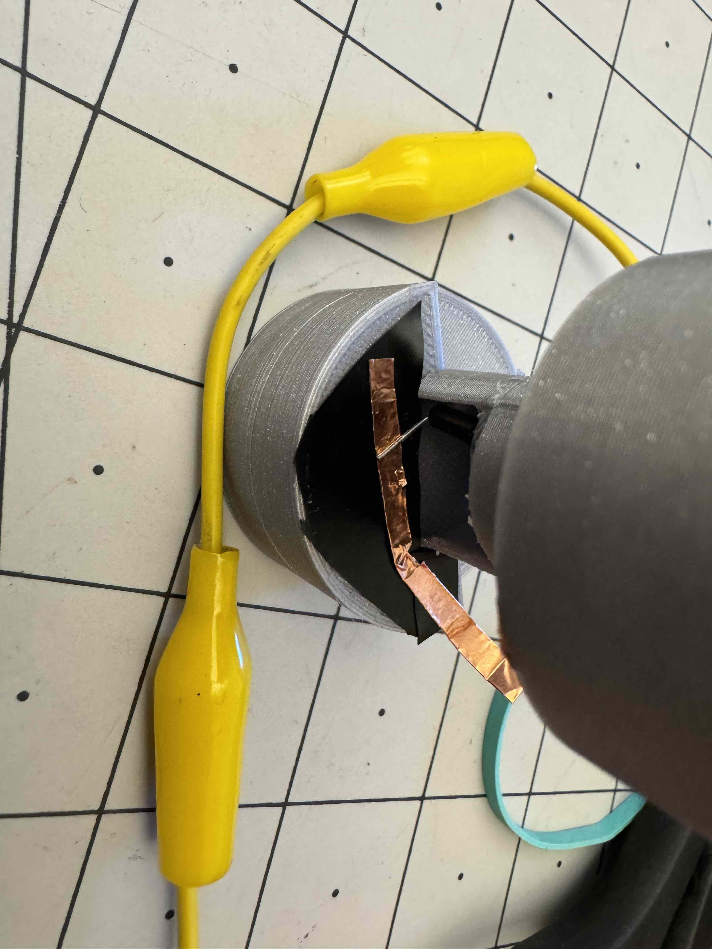
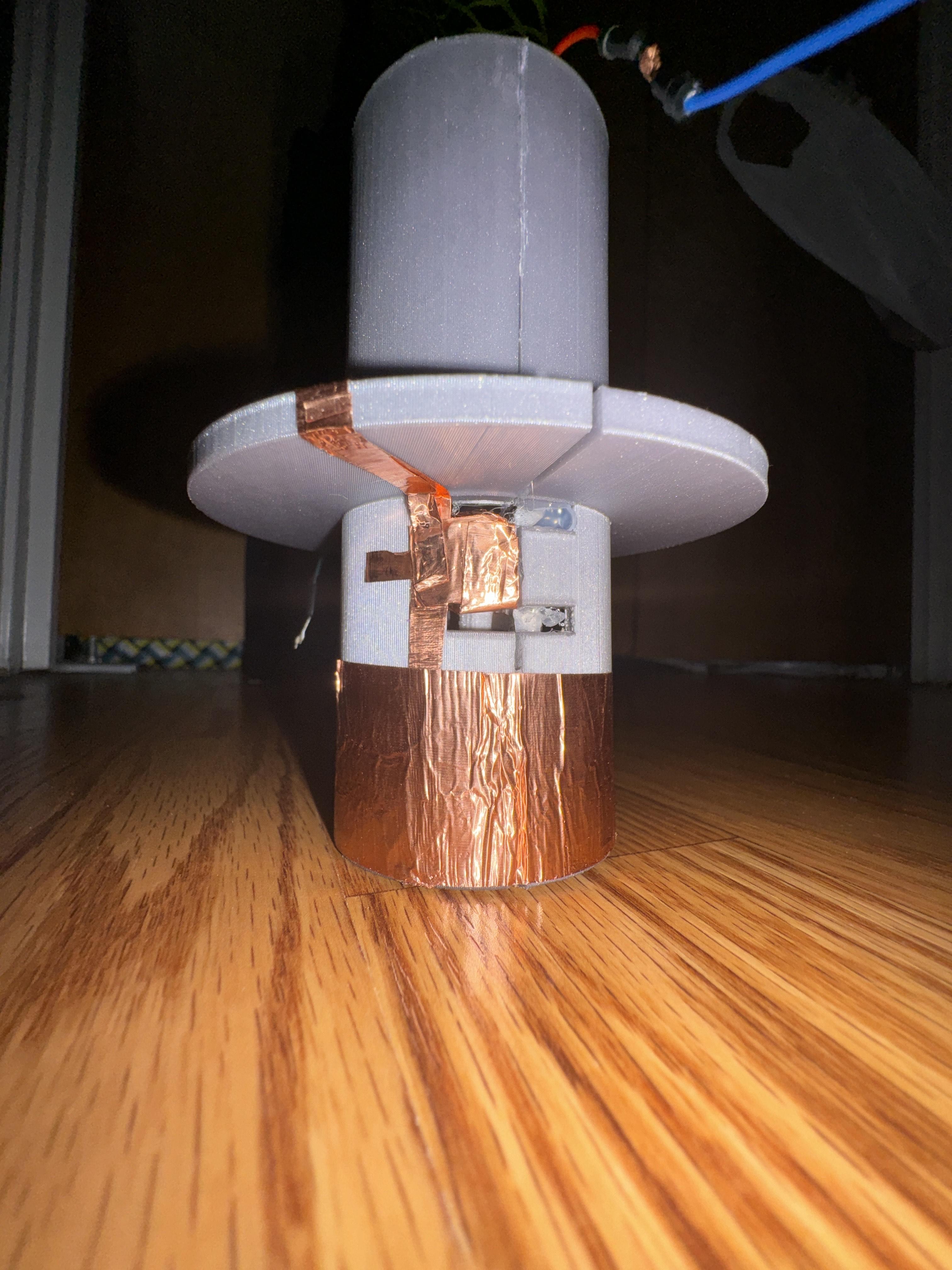
- Bend one end of two Arduino jumper cables into an L shape, as shown in the image above.
- Cover the piston's shorter end cavity in electrical tape first and copper tape above it.
- Add the L number cable to the bottom so it touches the copper tape, held in place with electrical tape on top.
- Do this for the two bases of the piston parallel with the central holes.
Add the Springs & Copper Tape to Piston Shell
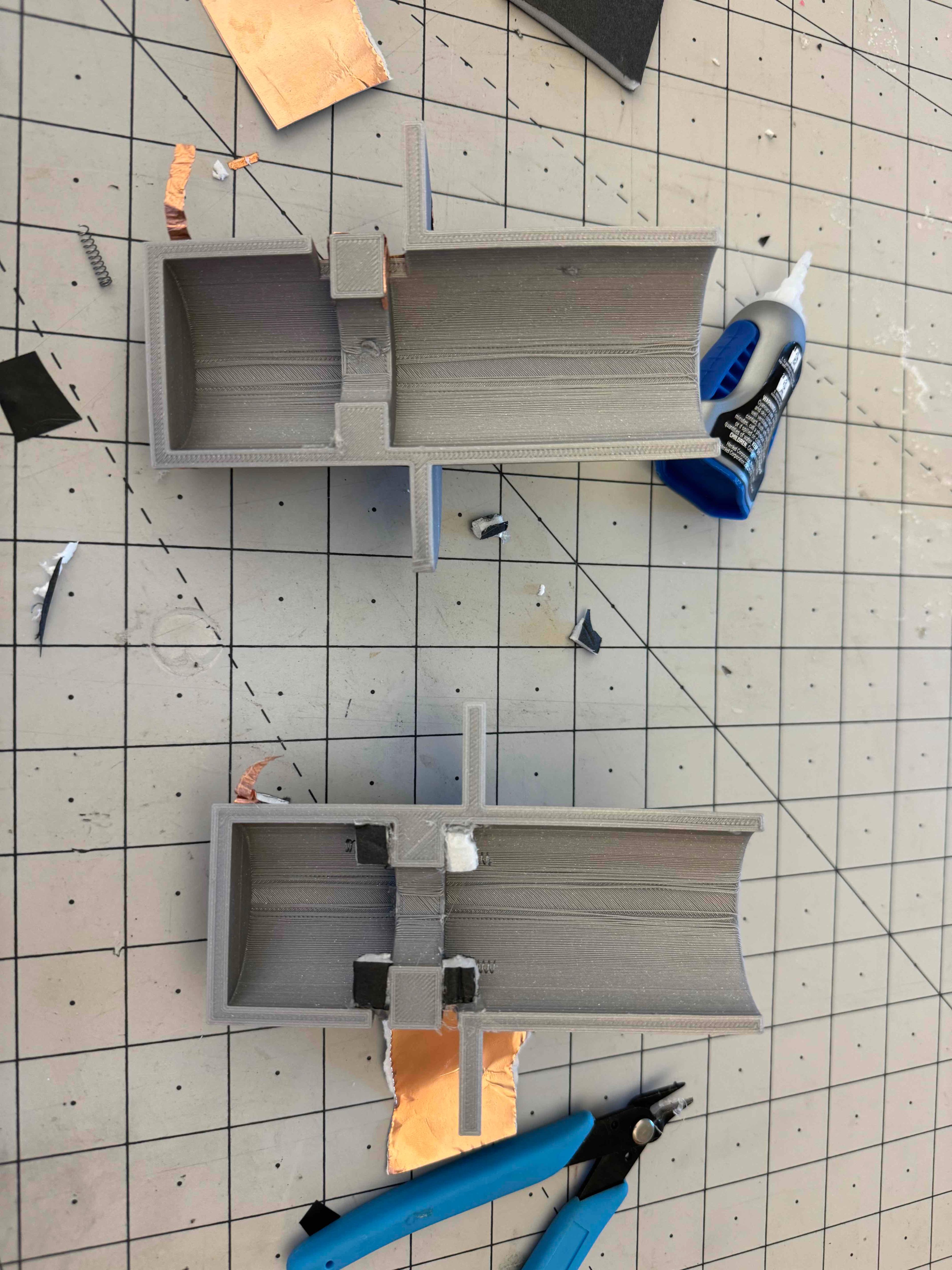
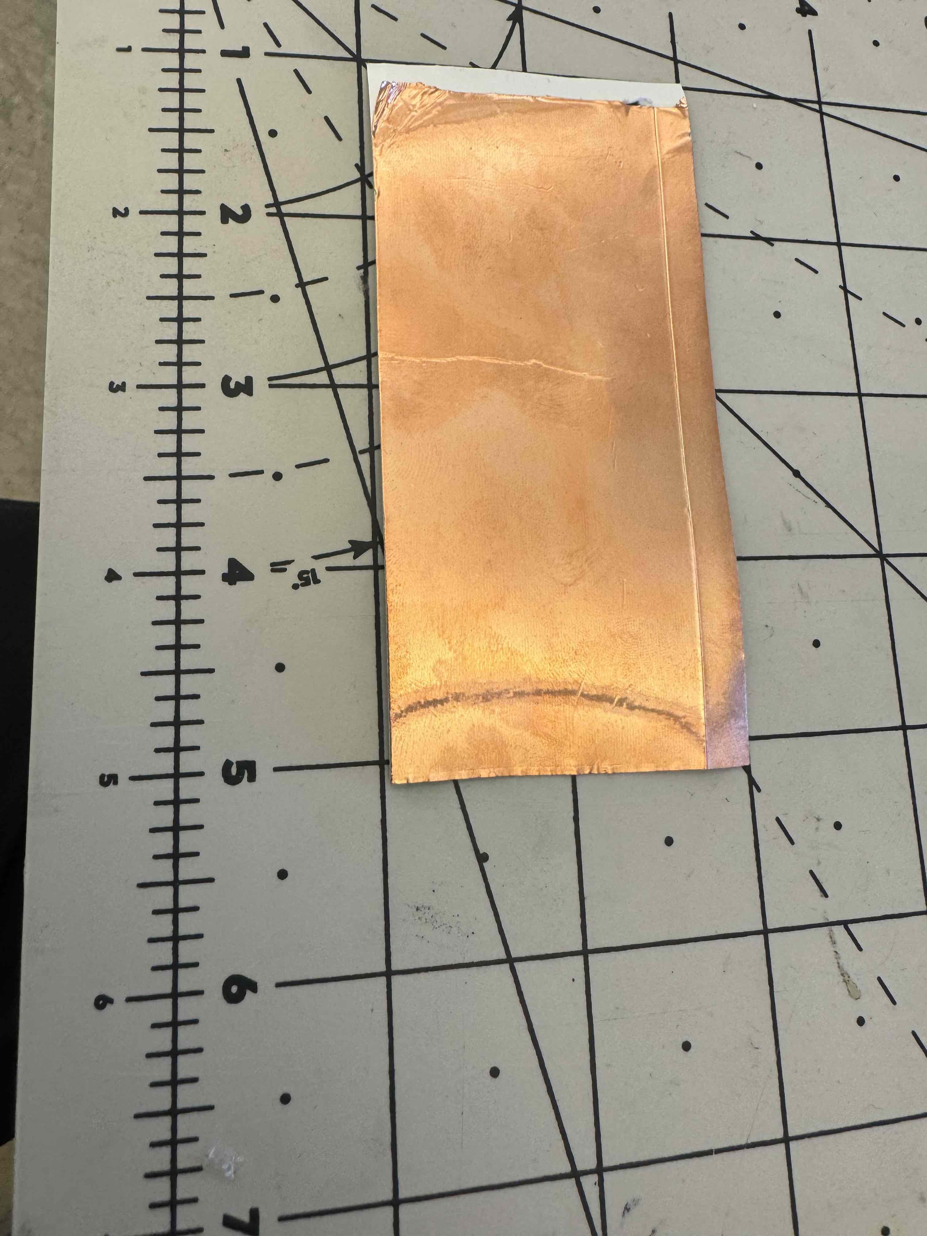
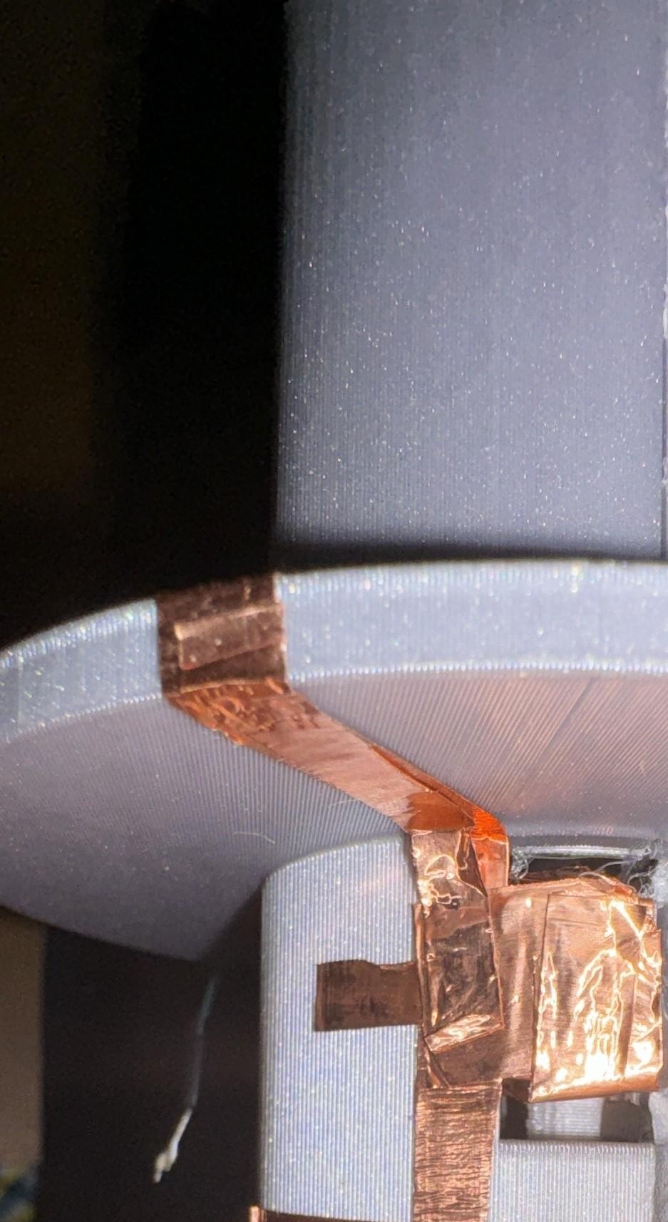
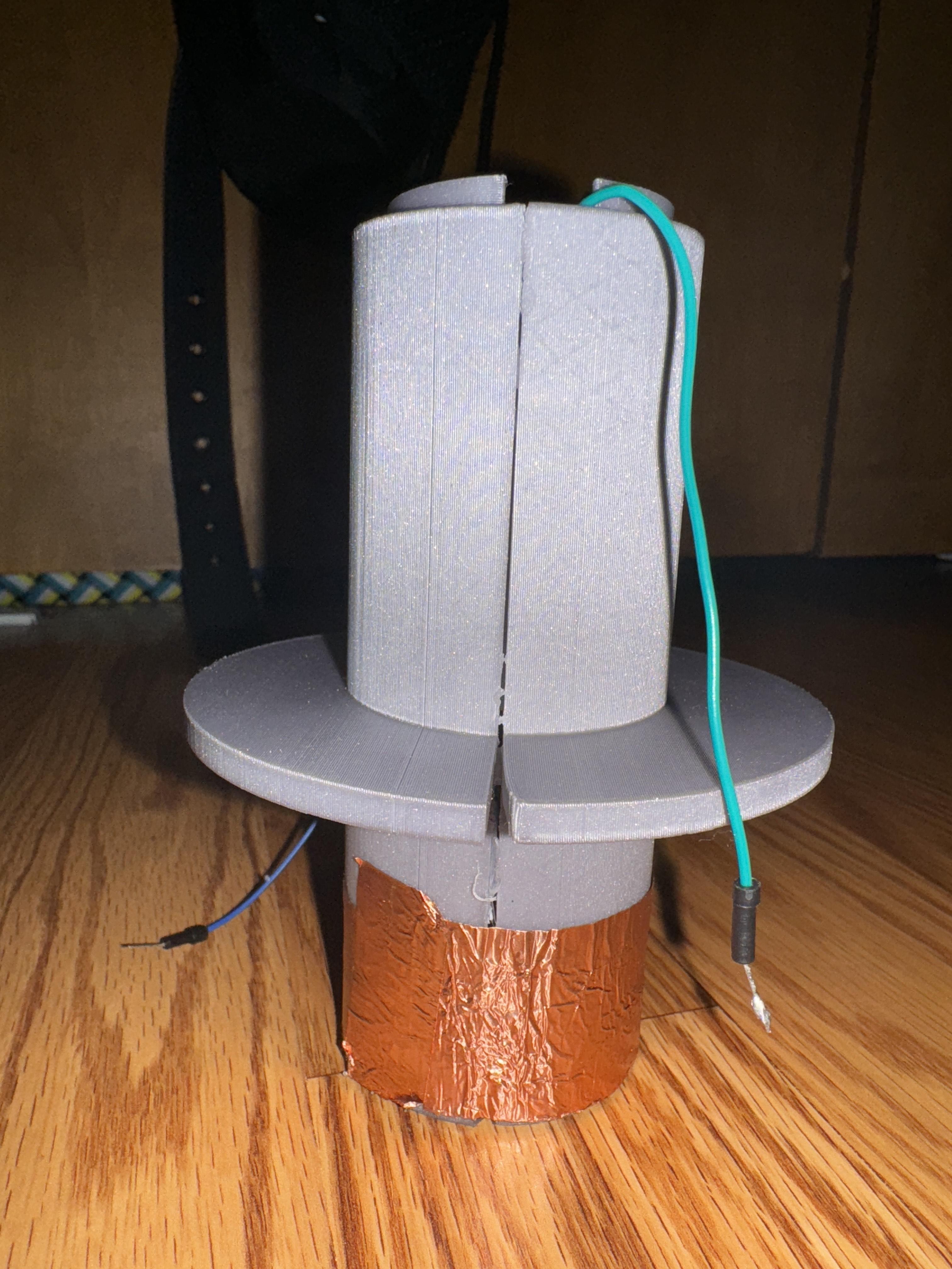
- On one inside of the piston shell (Piston X C), add copper tape that wraps the indents and outside the hole within the shell.
- Connect these two tape conglomerates with additional copper tape that wraps around the "brim" structure of the shell, where an alligator clip can be attached.
- On the other side of the piston shell(Piston X B), add three springs of equal length symmetrically close to the edge. Attach with either super or hot glue. The springs' length determines the force needed to press the left-click in the finished product. At least half an inch of spring length is required, but I would recommend adding more length.
Contain the Piston
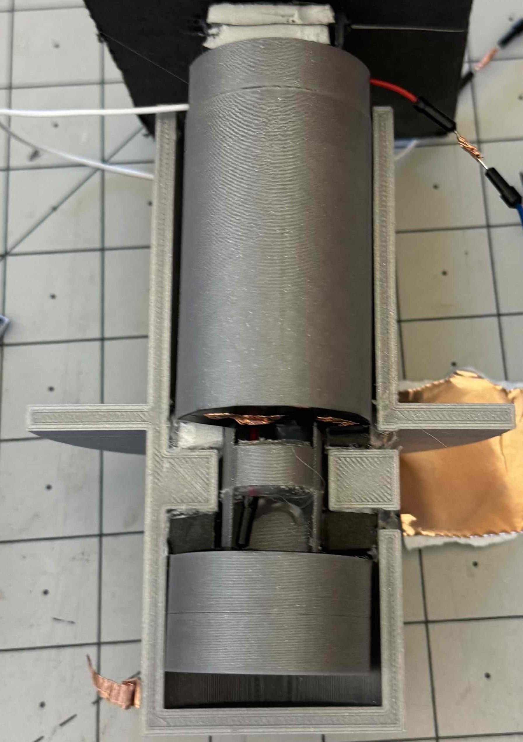
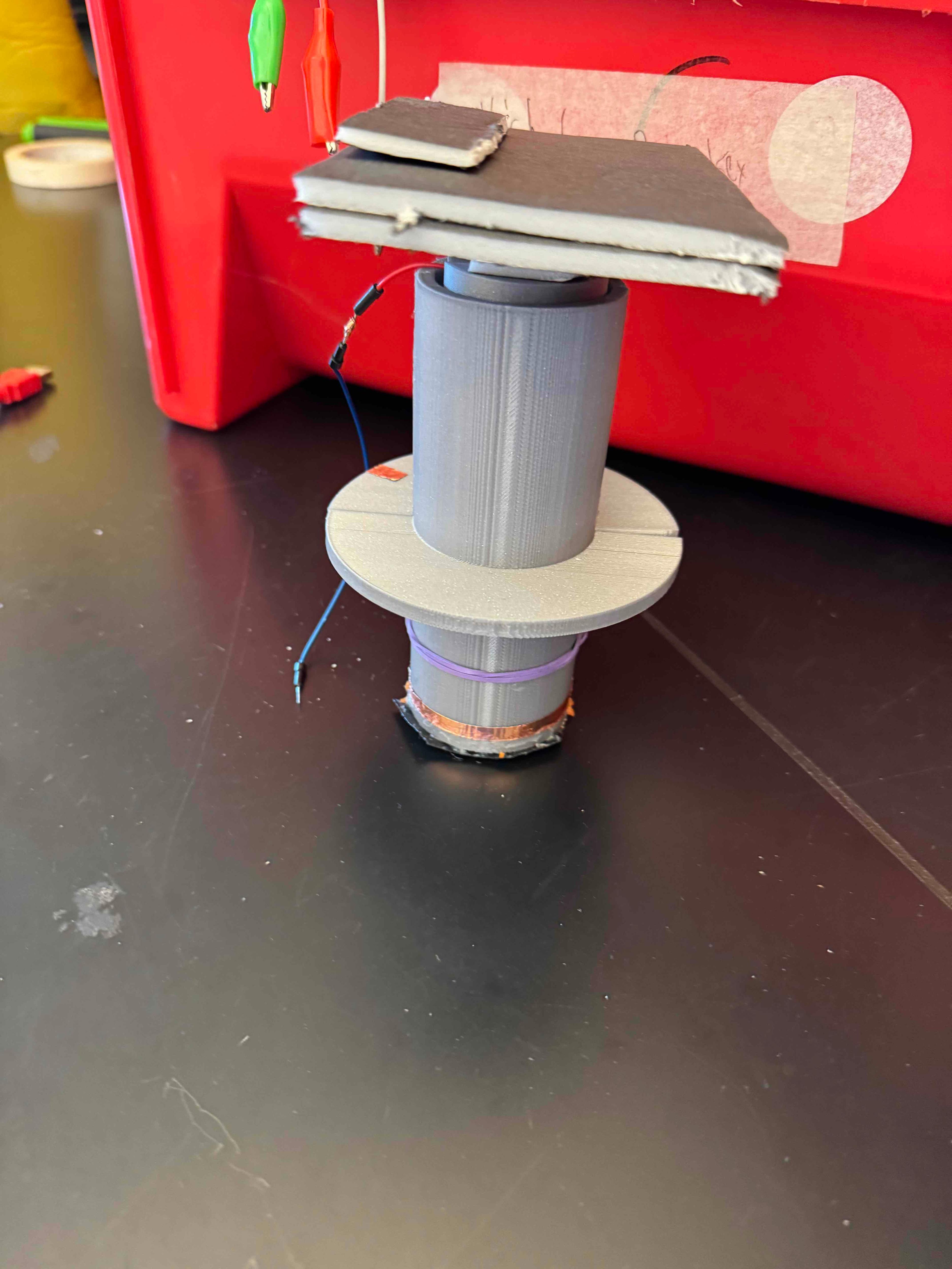
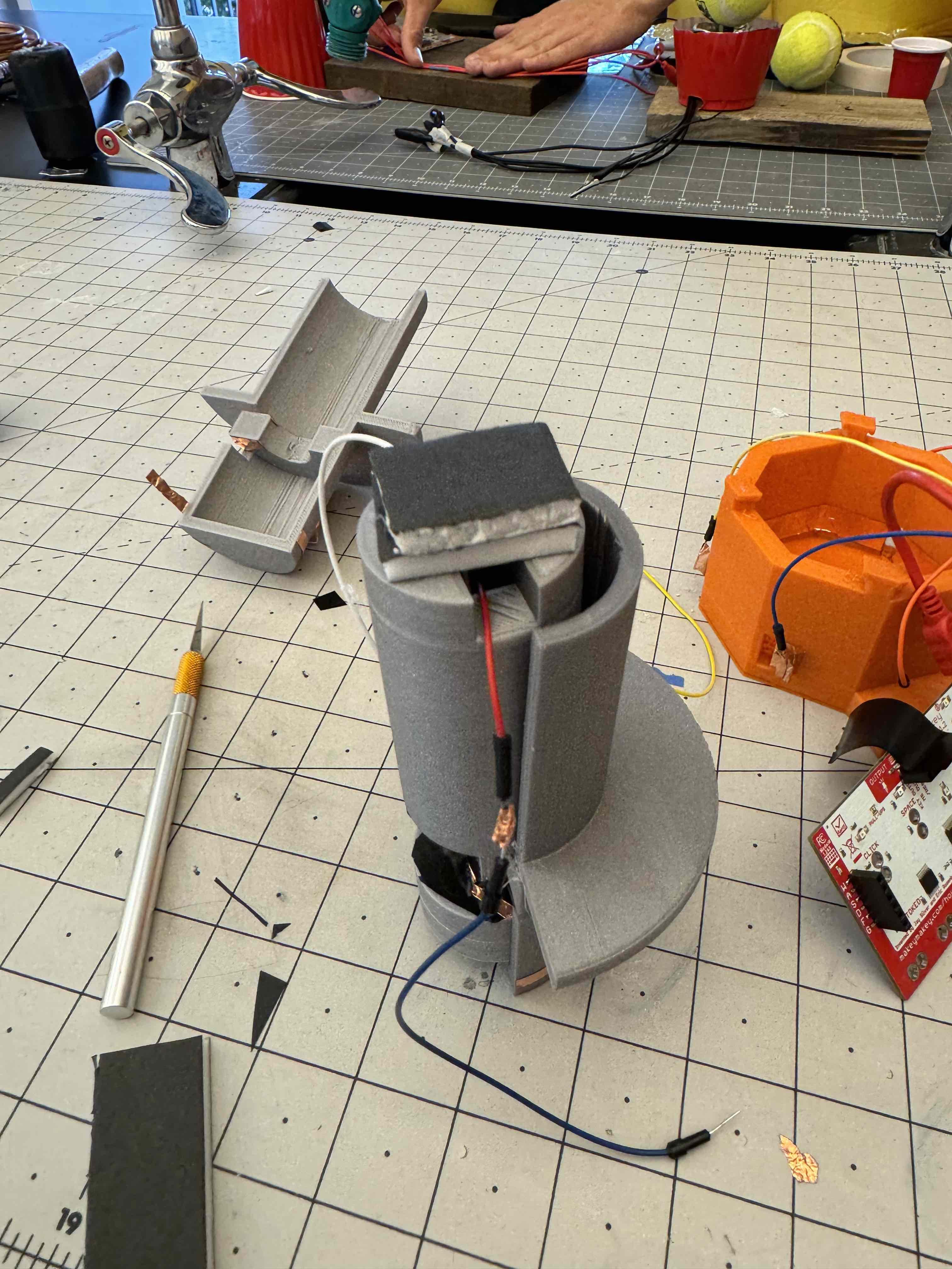
.JPG)
(Although this step can be completed with hot glue, I highly recommend super glue)
- Place the side of the piston with the larger open area beside the spring.
- Add super glue to the other piston shell (in this case, the one with the copper tape) and combine the two piston shells into a whole cylinder.
- After waiting for the glue to settle, check to see if the piston has a spring-like downward motion, smooth, and does not leave the piston shell.
- From the ground copper tape around the piston shell, add another piece that travels to the bottom of the module.
- Wrap around the shell a 1-inch wide piece of copper tape slightly longer than the circumference of the piston shell, and ensure there is little space between the copper tape and the visible bottom of the piston shell.
Add Copper Tape/wires to the Base
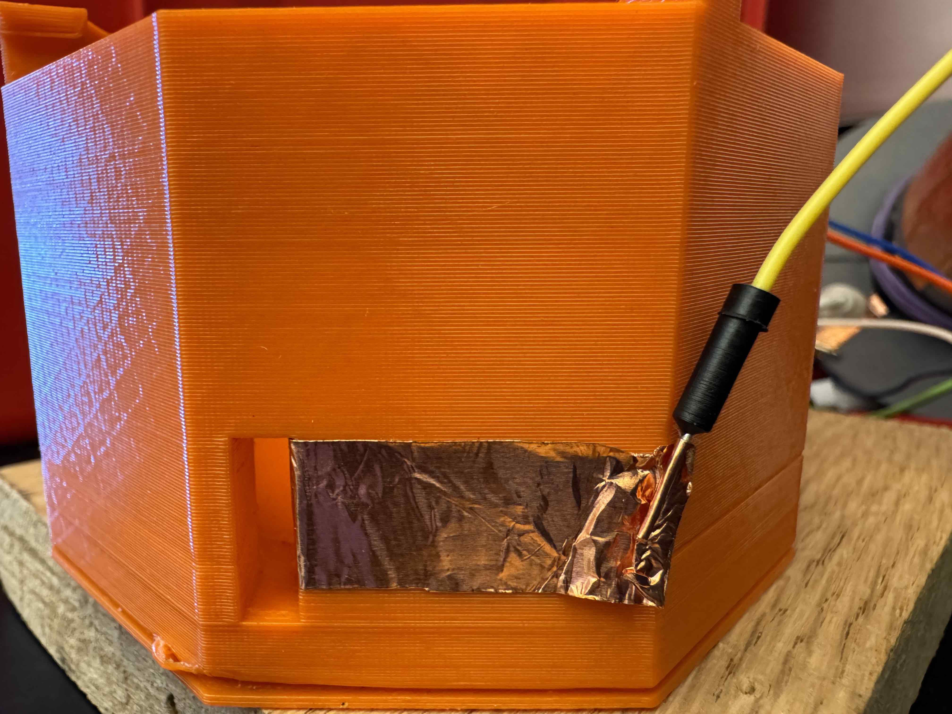
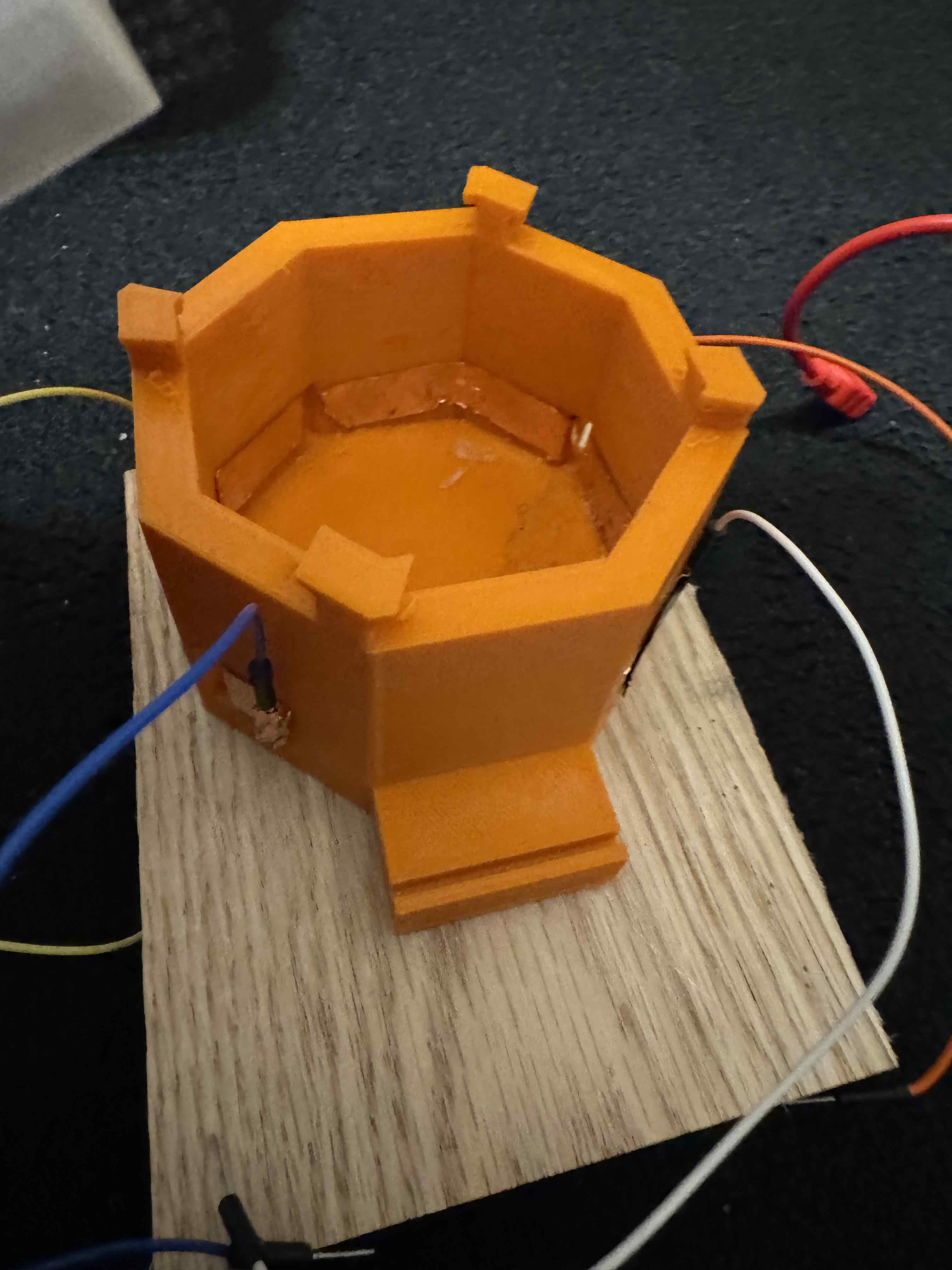
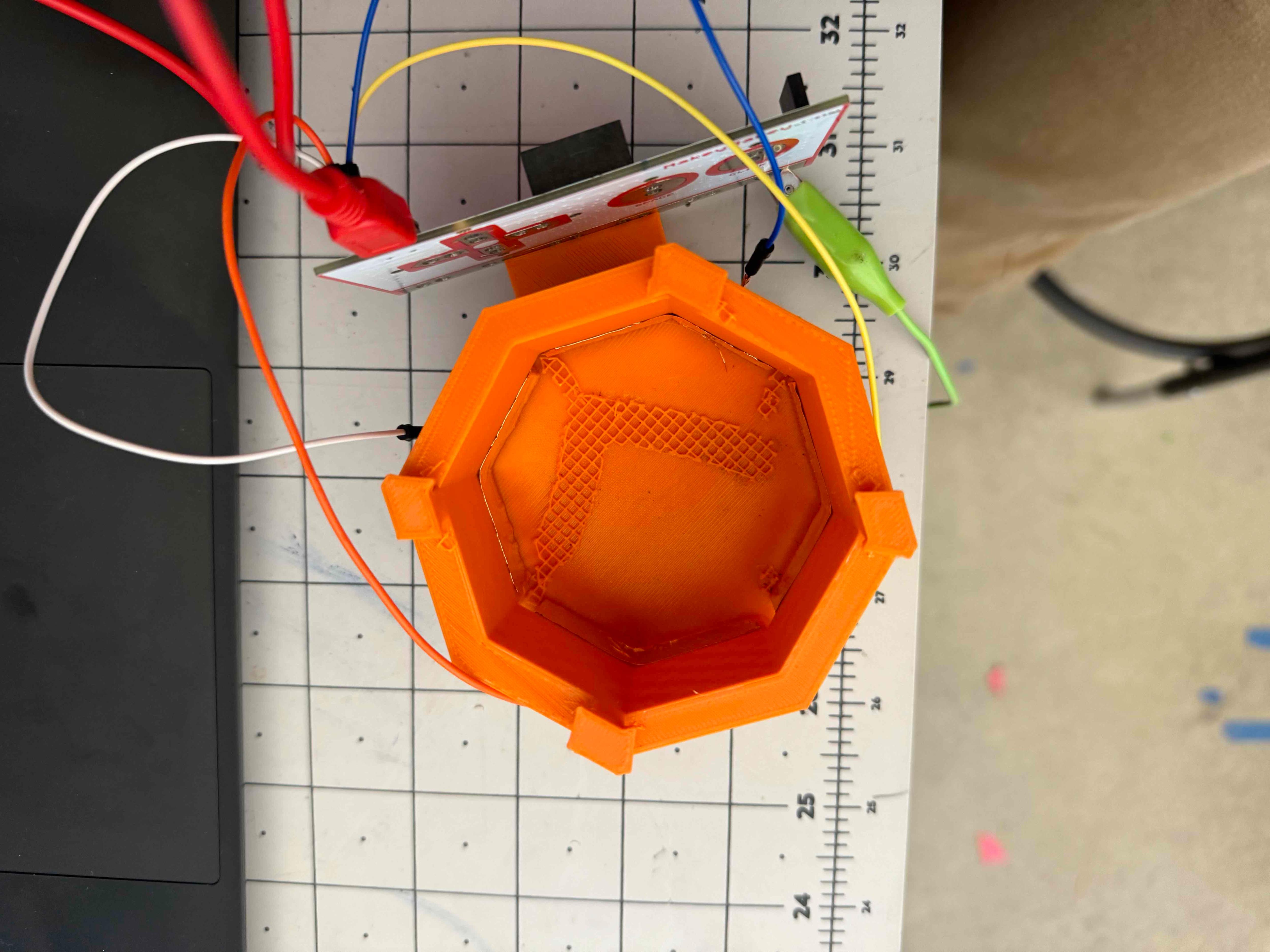
- Cut four 0.5x4 inch long copper tape.
- As shown in the image above, add each tape through the holes within the joystick base until the end of the tape inside the base reaches the edge of a separate hole. Ensure there is little space between the tape and the floor of the joystick base.
- On the other side of each tape, neatly wrap around one Arduino jumper cable like a sushi roll, with the rest of the cable facing upward. You may need electrical tape to create better contact between cable and copper.
Rubber Bands!
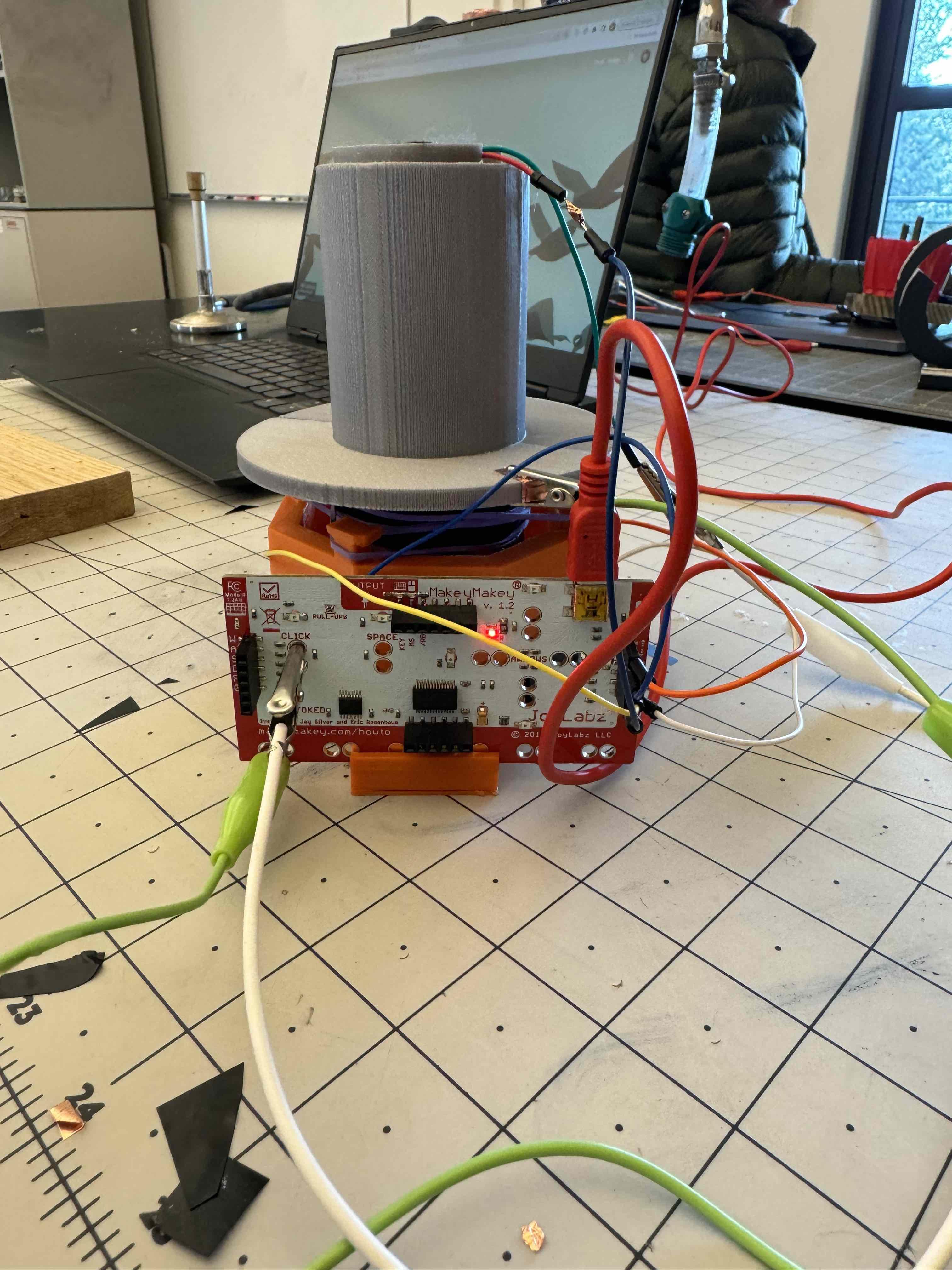
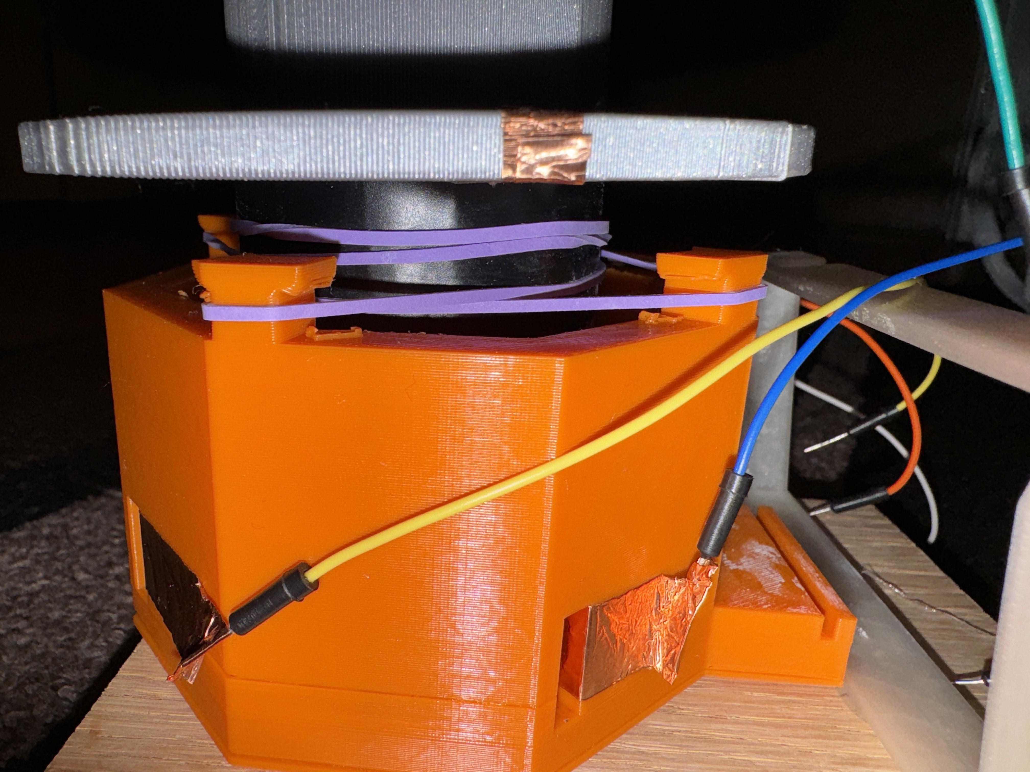
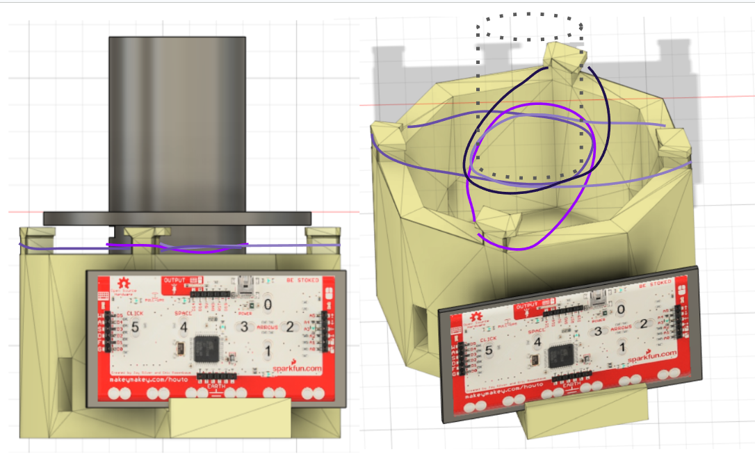
- Wrap around the bottom of the "brim" structure of the piston electrical tape to prevent the rubber bands from contacting the copper tape.
- Add four rubber bands within this area and extend each into a separate holder located on top of the joystick base.
Connect All of the Wires!
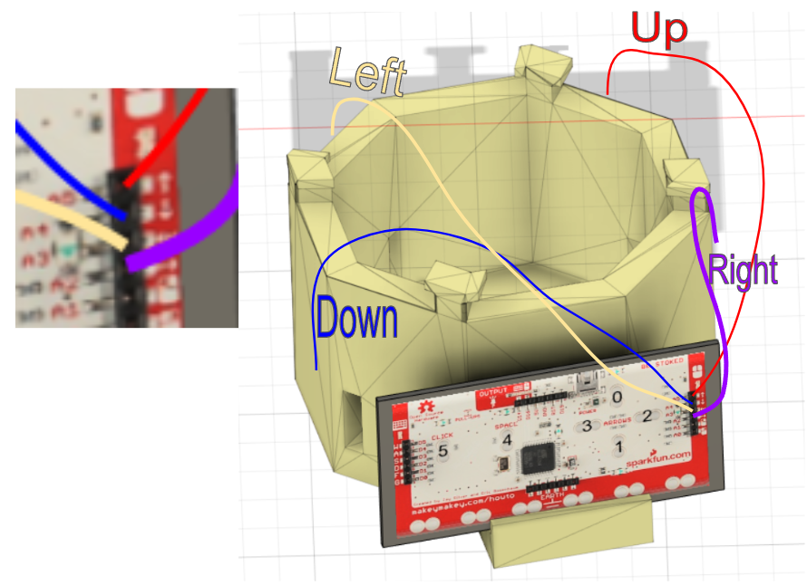
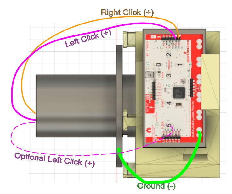
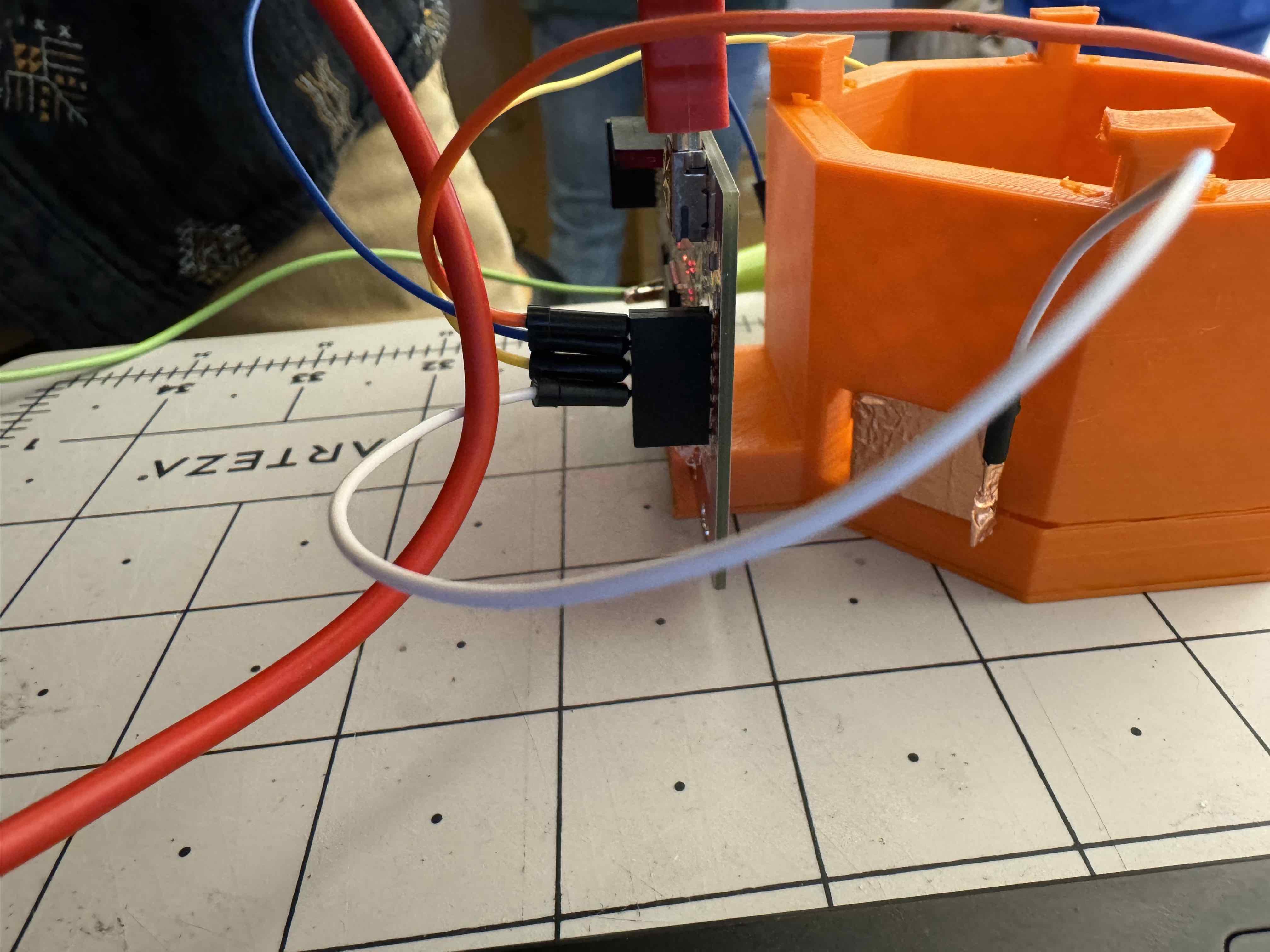.JPG)
(Labelling all of the wires with their respective keys is recommended)
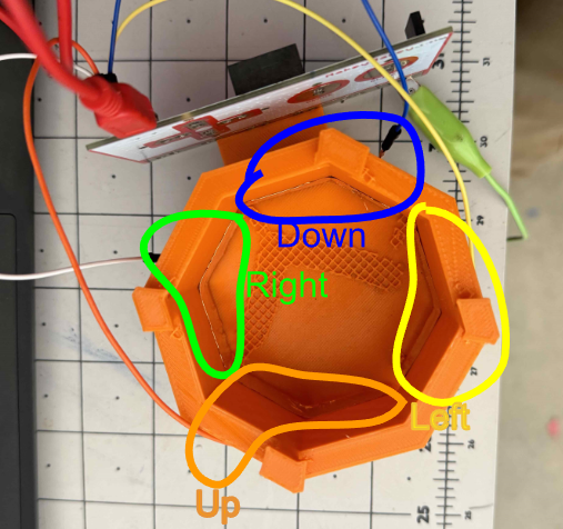
In the image above, a diagram is shown that depicts which wires go where in a simple fashion.
The Ground wire is the only wire that uses an alligator clip (disregarding the optional setup for the left-click), and the rest use Arduino jumper cables. If a cable is not long enough, connect one end to another end of a separate new cable with electrical or copper tape.
Modular Pieces
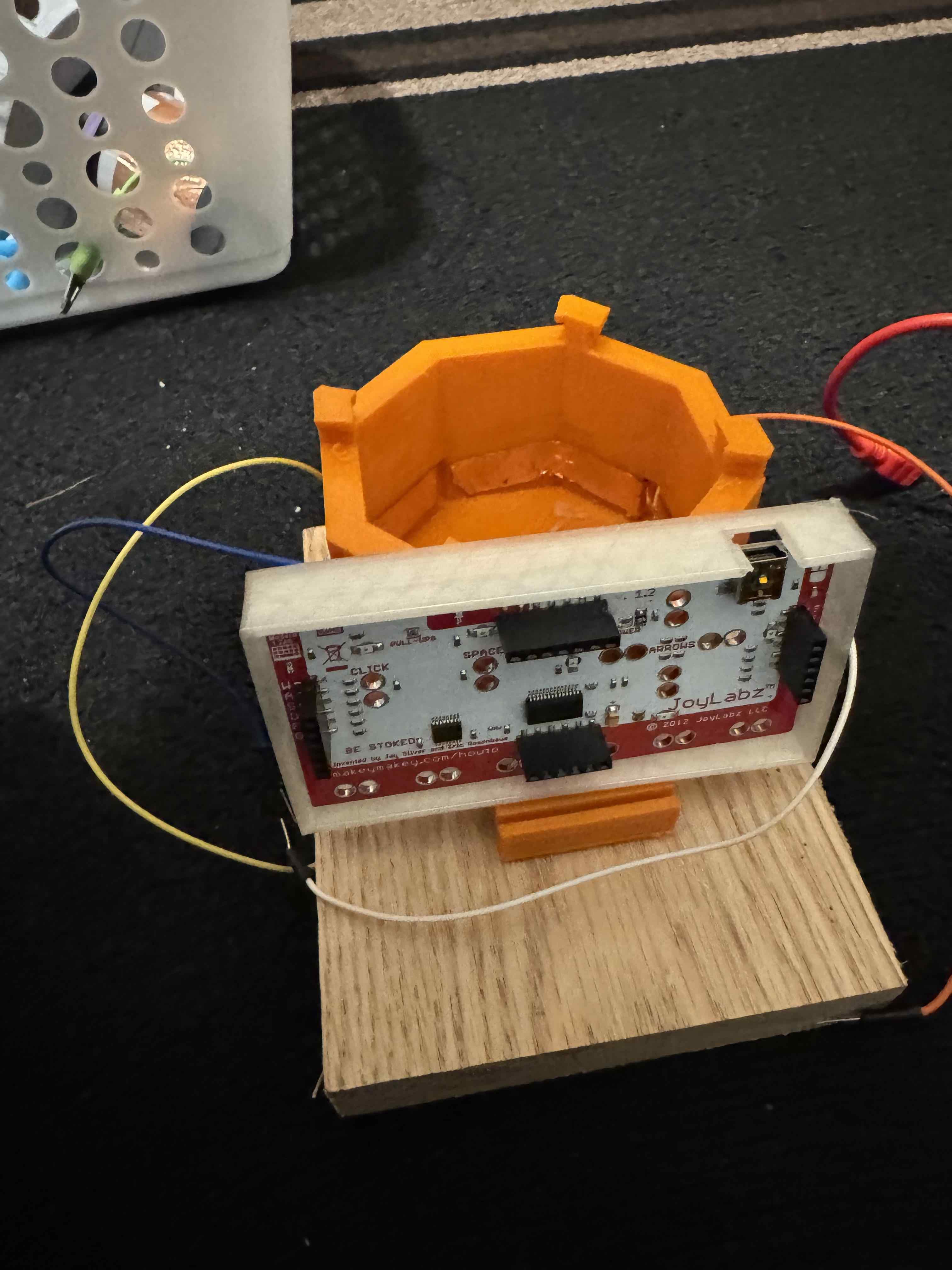
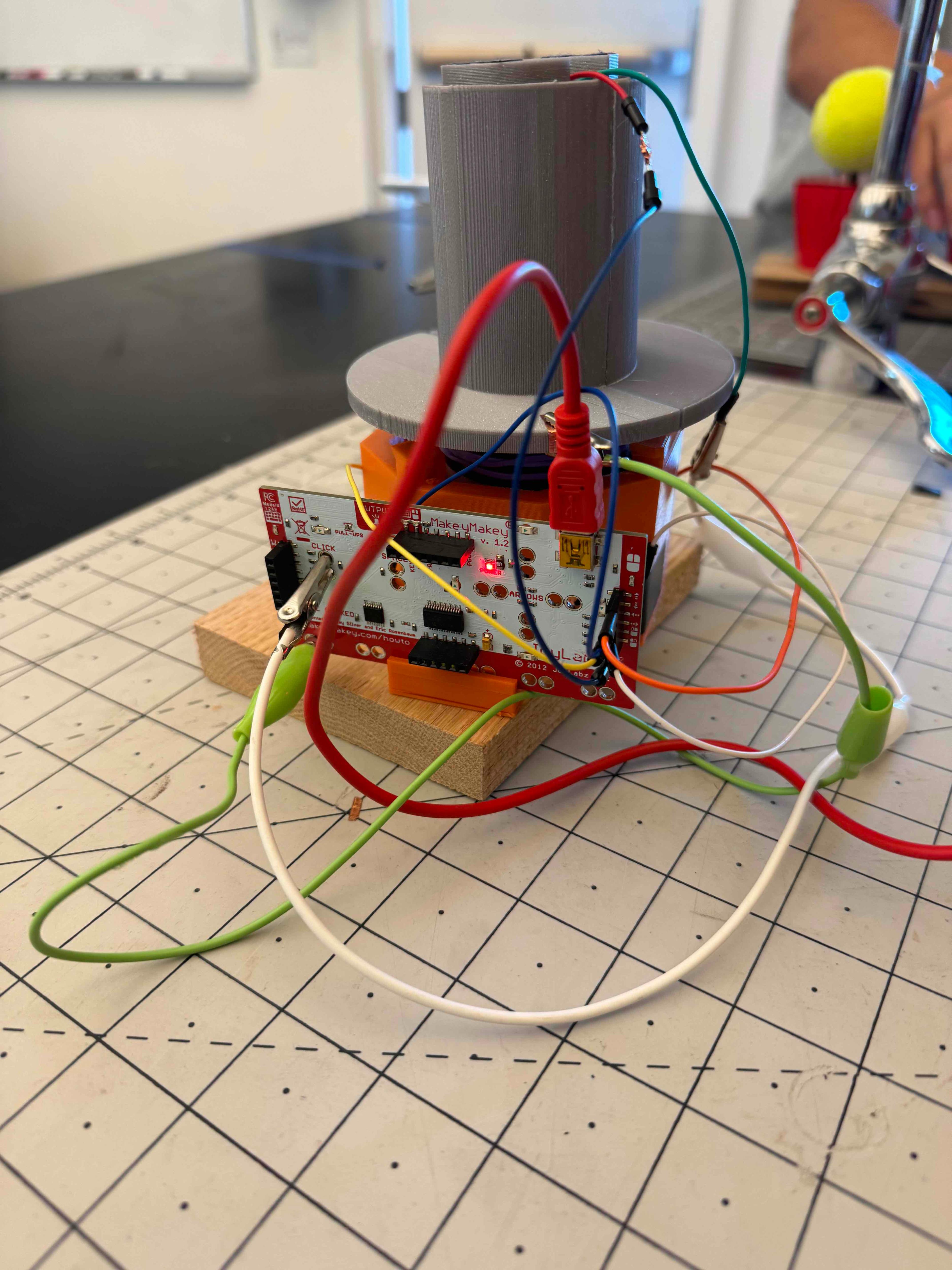
Here are some 3D prints (below) you can super glue to the top of the joystick based on specific needs. Similarly, I recommend attaching the bottom of the joystick base to external materials to hold it in place. I added a wood board under the base, which can be clamped down to grip the table surface.
If you would like a more protected Makey Makey, a case for it is linked below as a 3D print.
How to Use Device
Use this Scratch game to test mouse controls. The right-click can be tested with this website.
Any Further Questions?
Comment below!