3D Printed CNC
In this instructable, I'm going to show how to build your own 3D printed CNC and all the parts you need to build it, and I will also give you my design and the material needed to make this project
Supplies
1x 12v power supply
1x Arduino
1x CNC shield
3x a4988
4x lm8uu
3x threaded rod
3kg PLA filament
3x couples 5mm x 8mm
wires
wood
5 meters Arkansas aluminum
30x ender 3 bearings
nuts and bolts
3x Nema 17 stepper motor
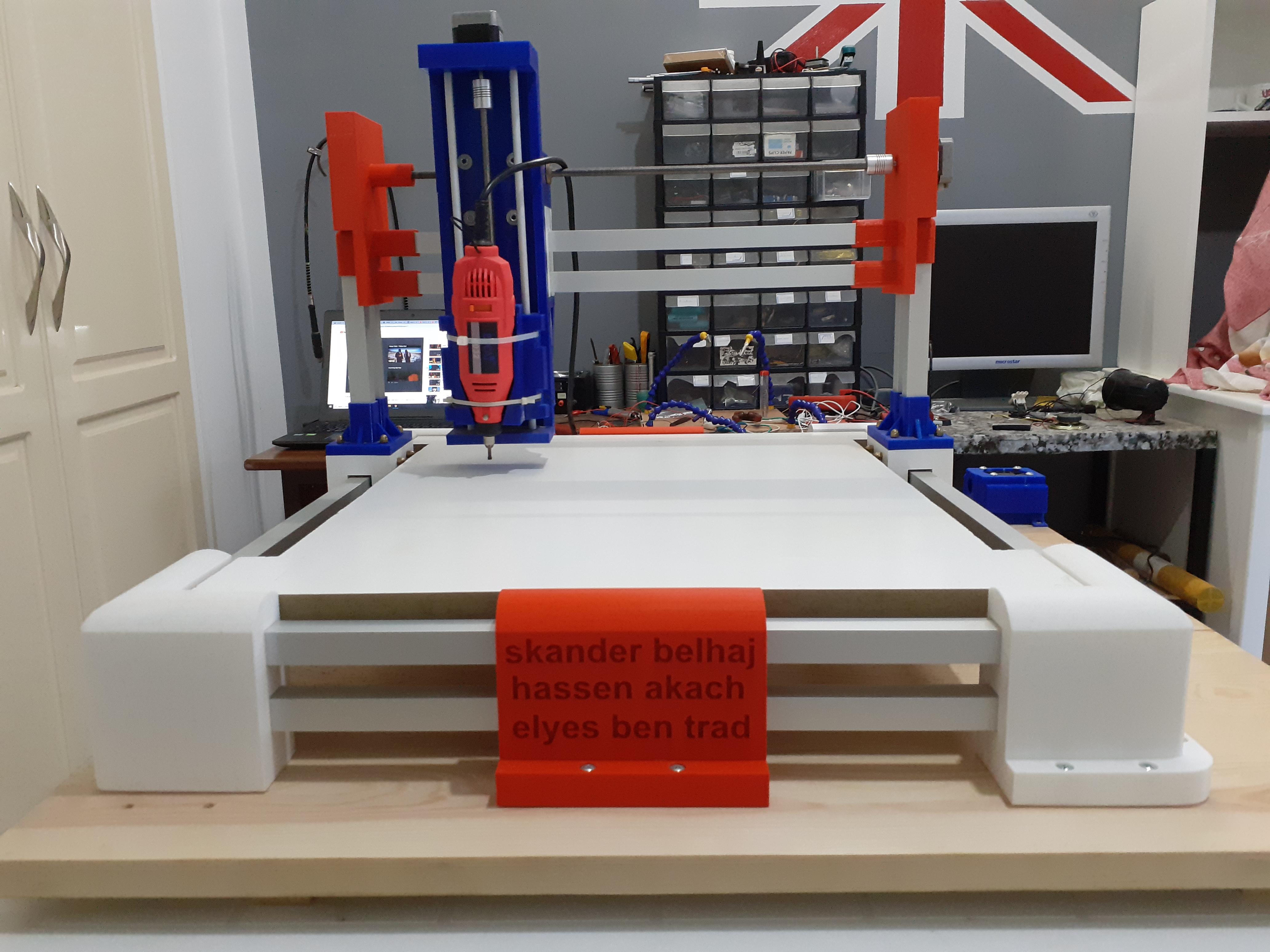
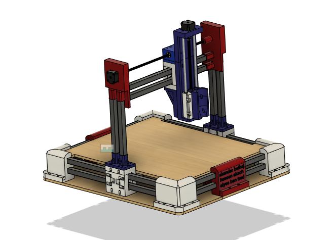
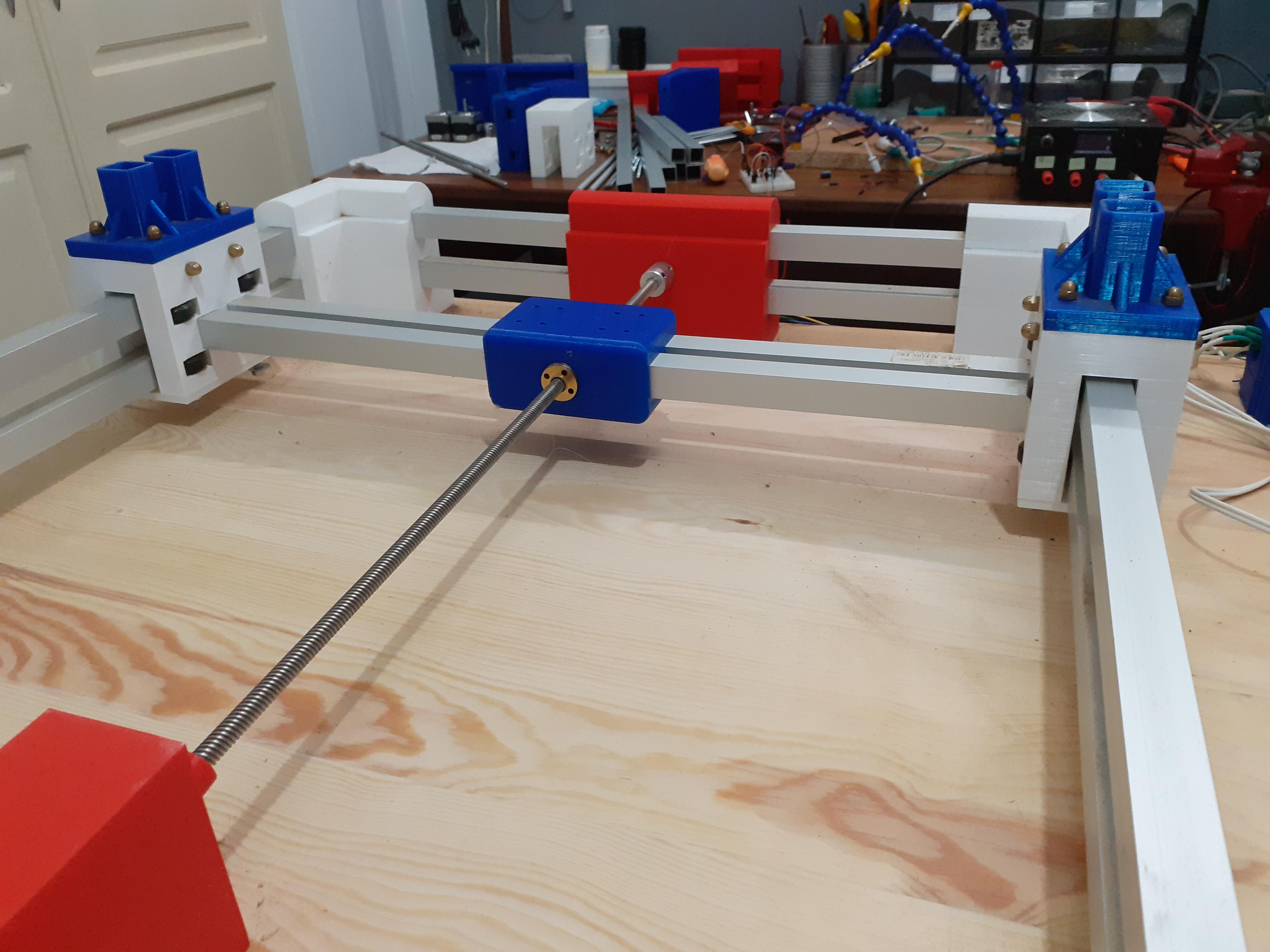
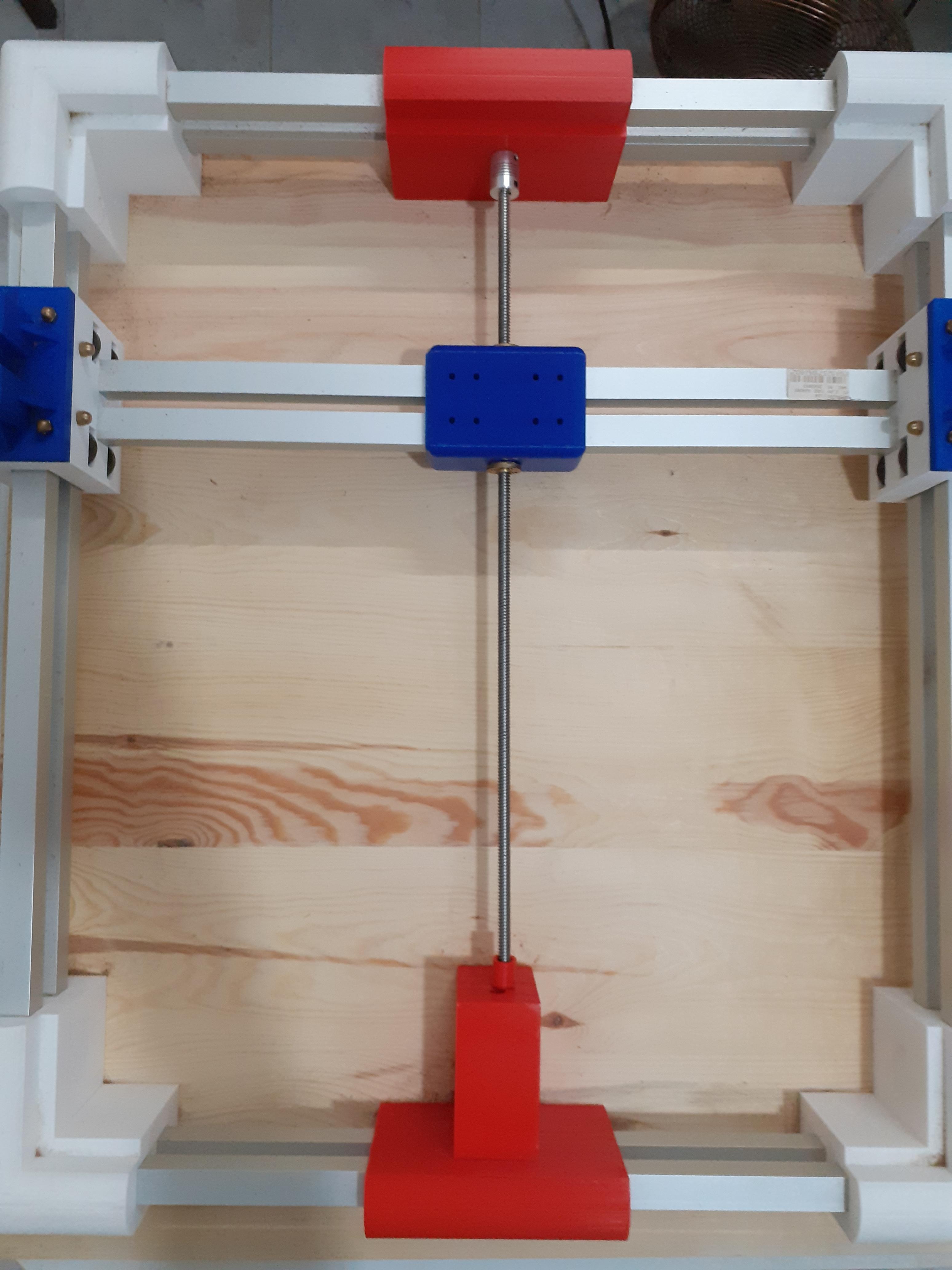
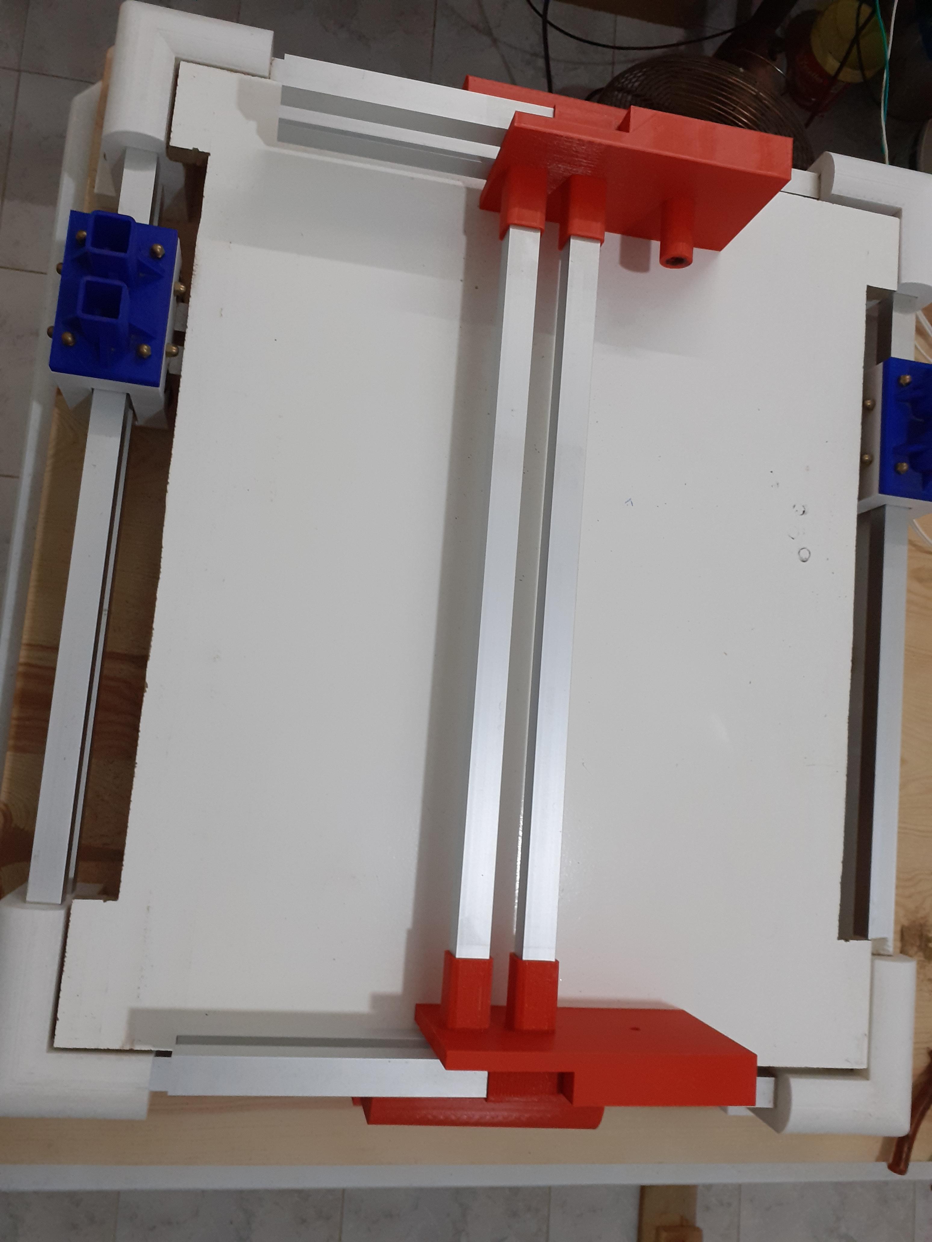
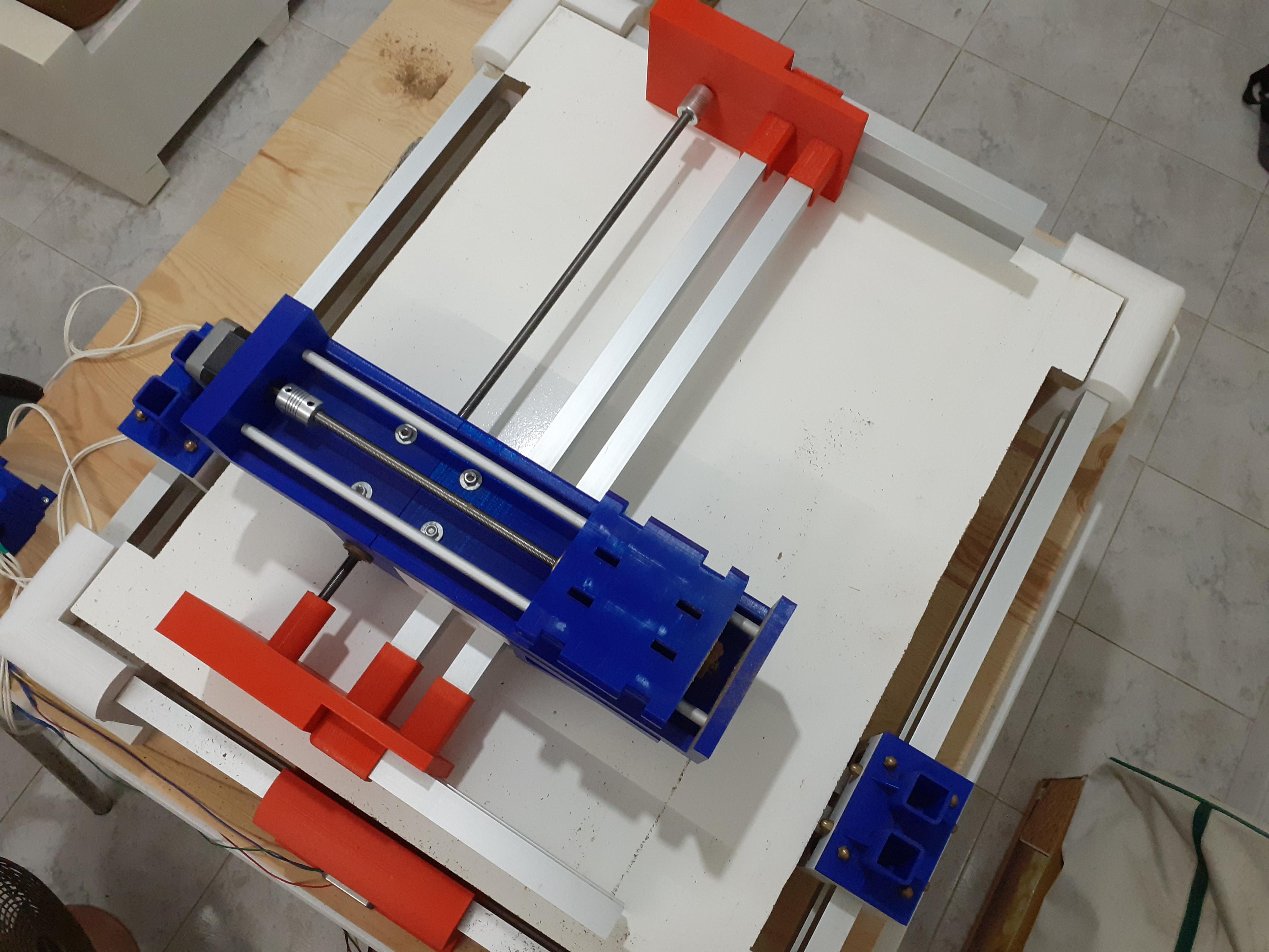
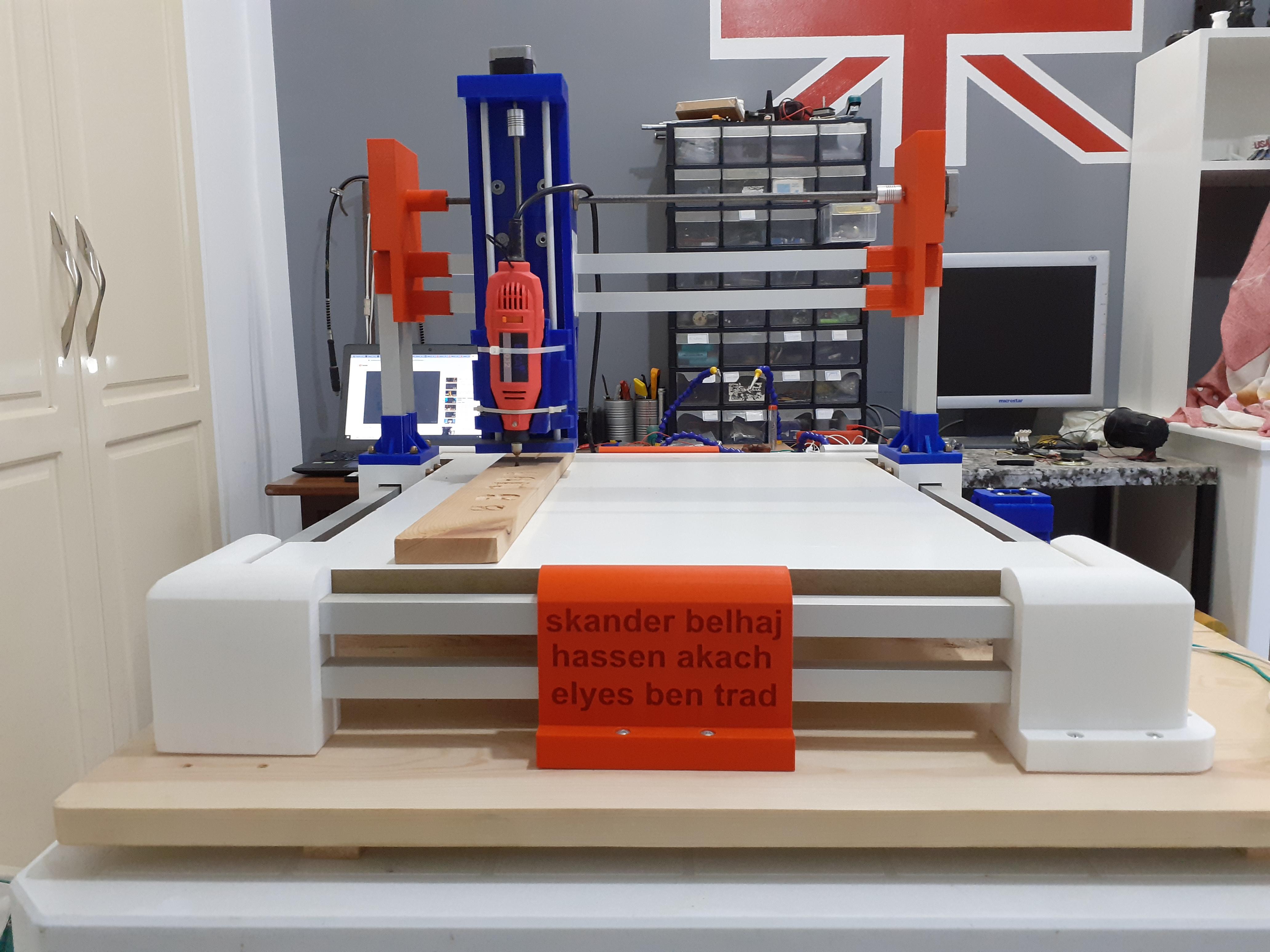
The CNC
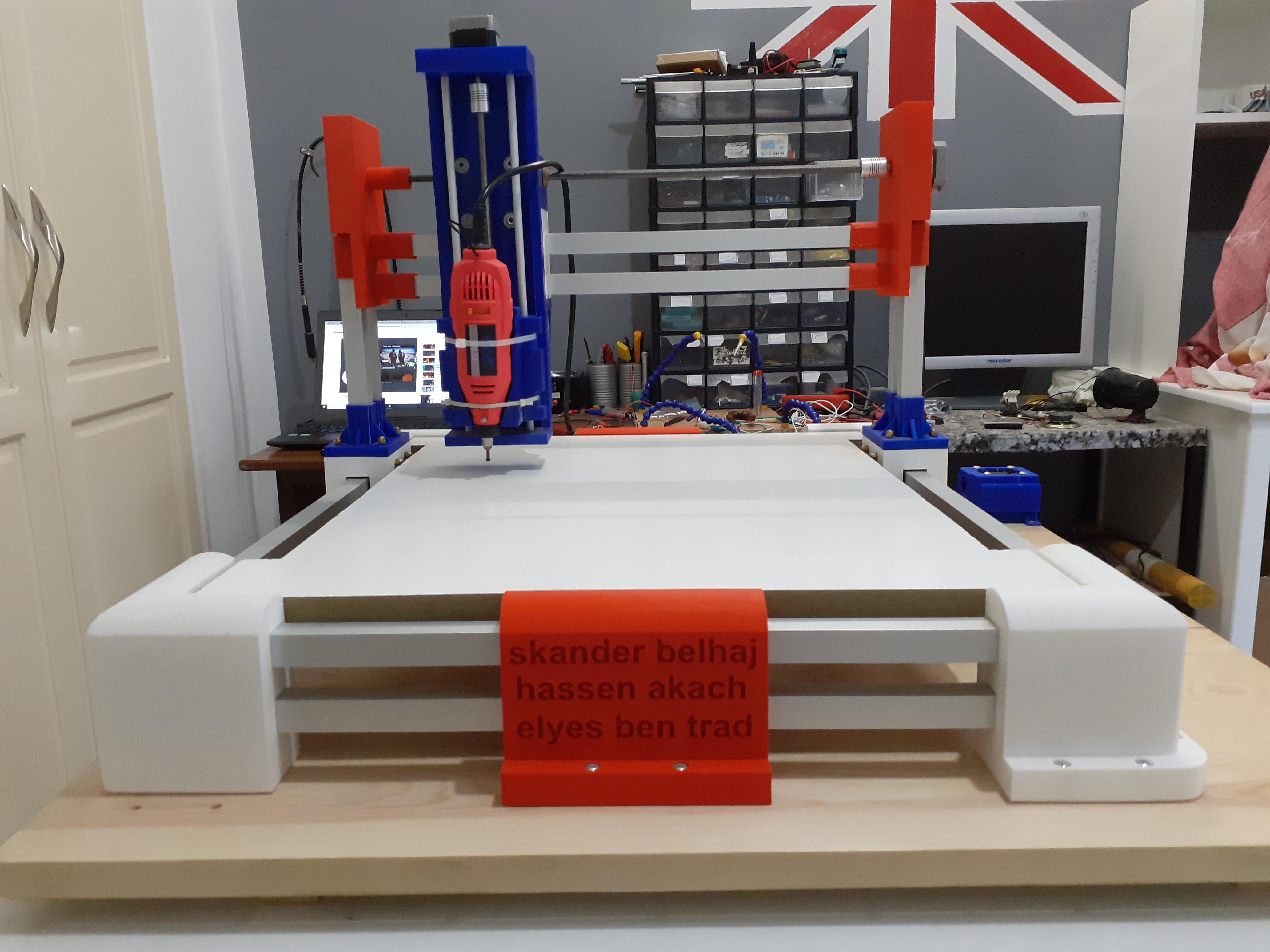

this a closer look about the CNC we're about to build together
I designed the whole machine with fusion 360
Print All Your Parts and Check for Measurement
these are all the parts you need to start working so make sure you print them correctly and not waste any filament cause it's gonna take some time
Downloads
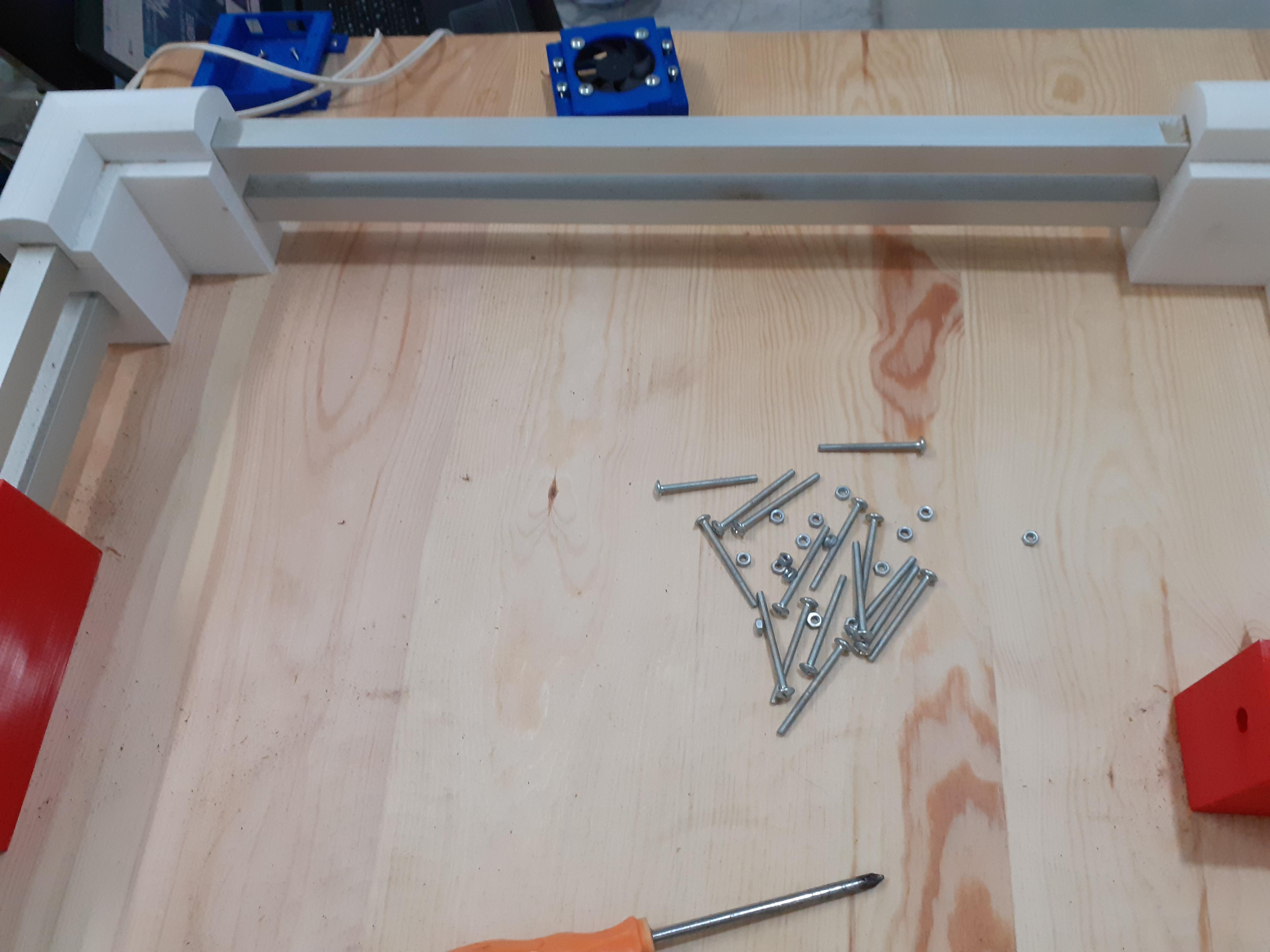
Gather the Printed Parts and Electronics
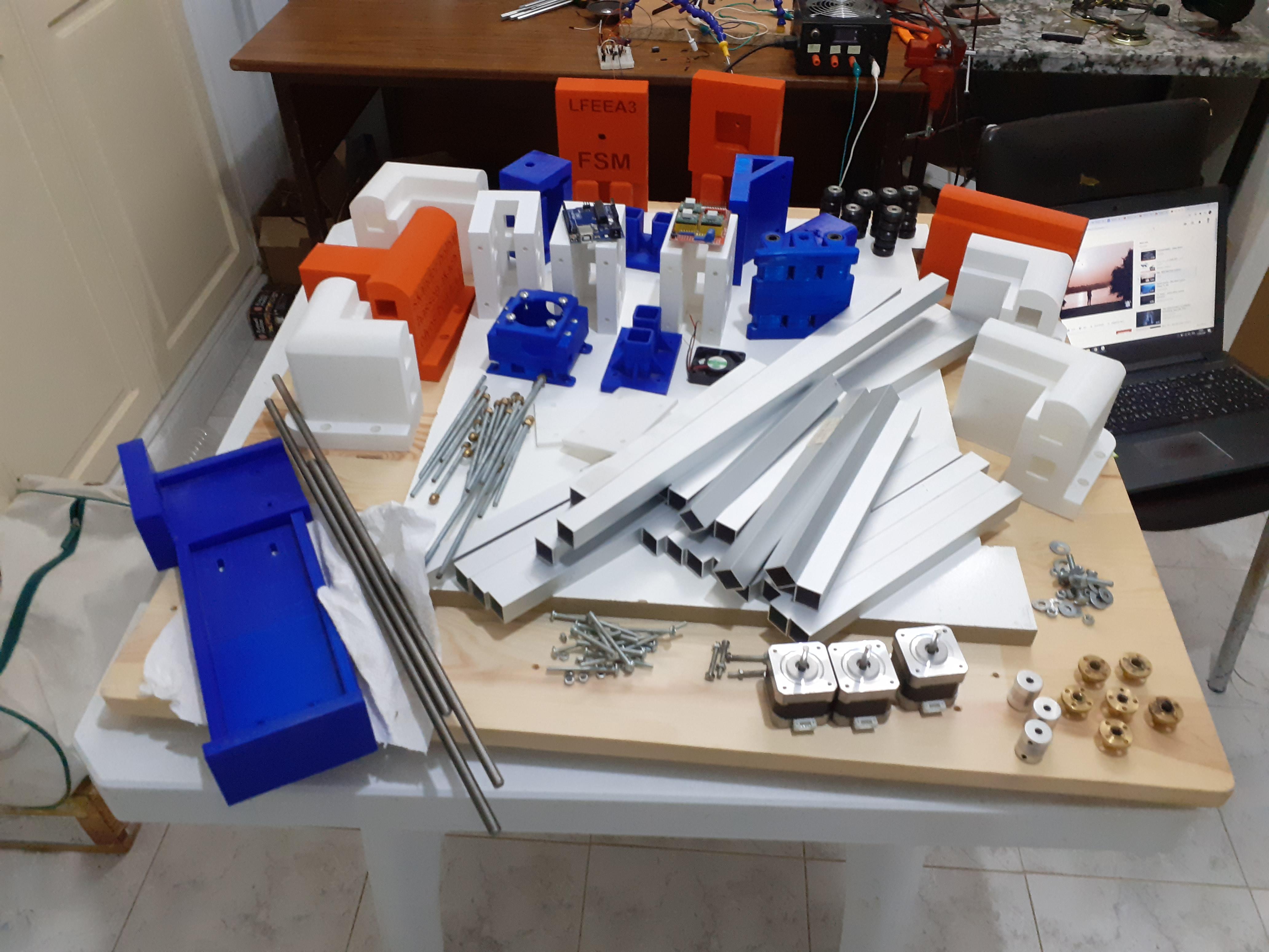
if you have a 3d printer download the STL files and print them ....this will take a while probably a week but it will be worth it and in the meantime go get the electronic components and follow my instructions cause we're going to build it together
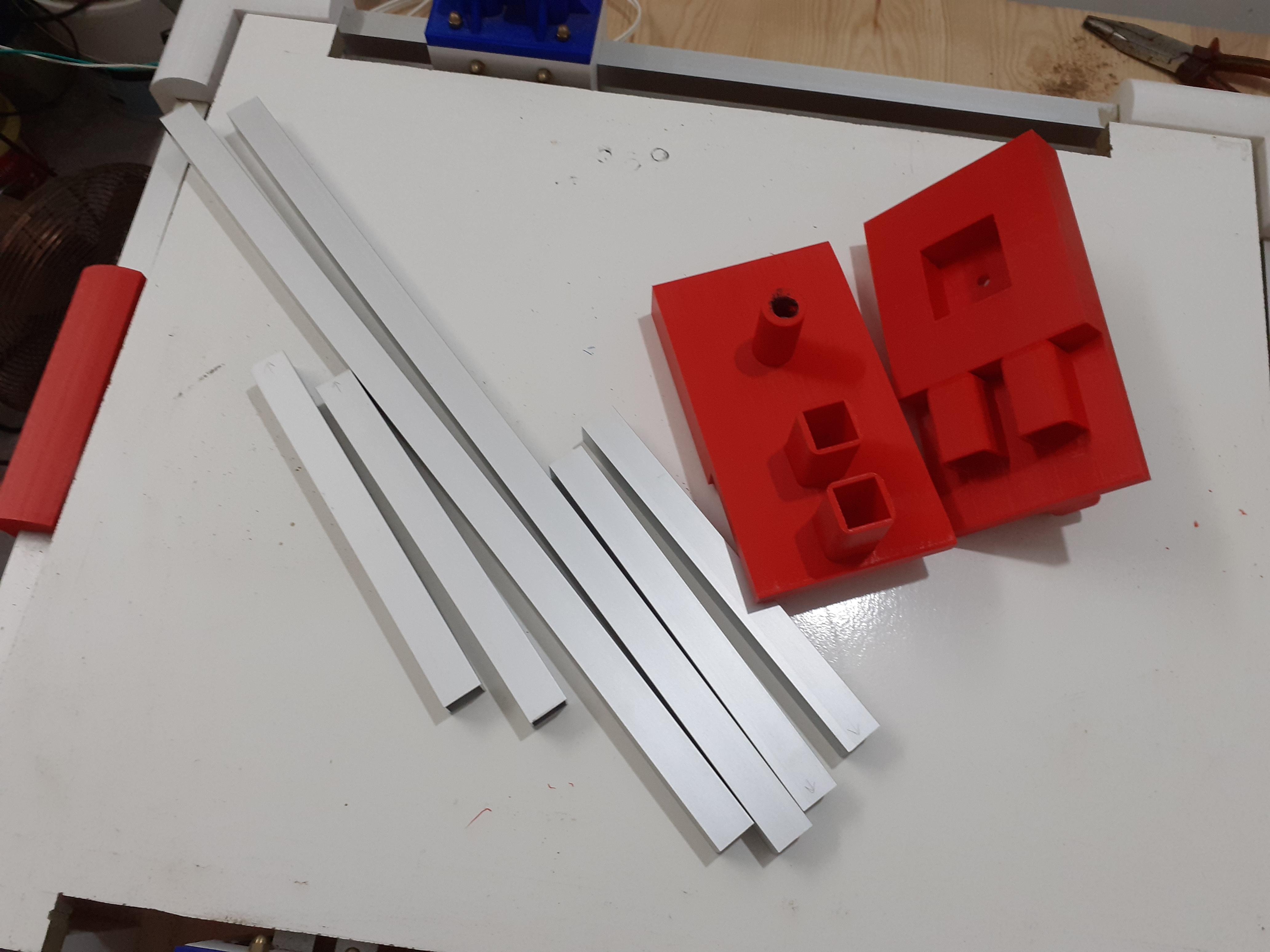
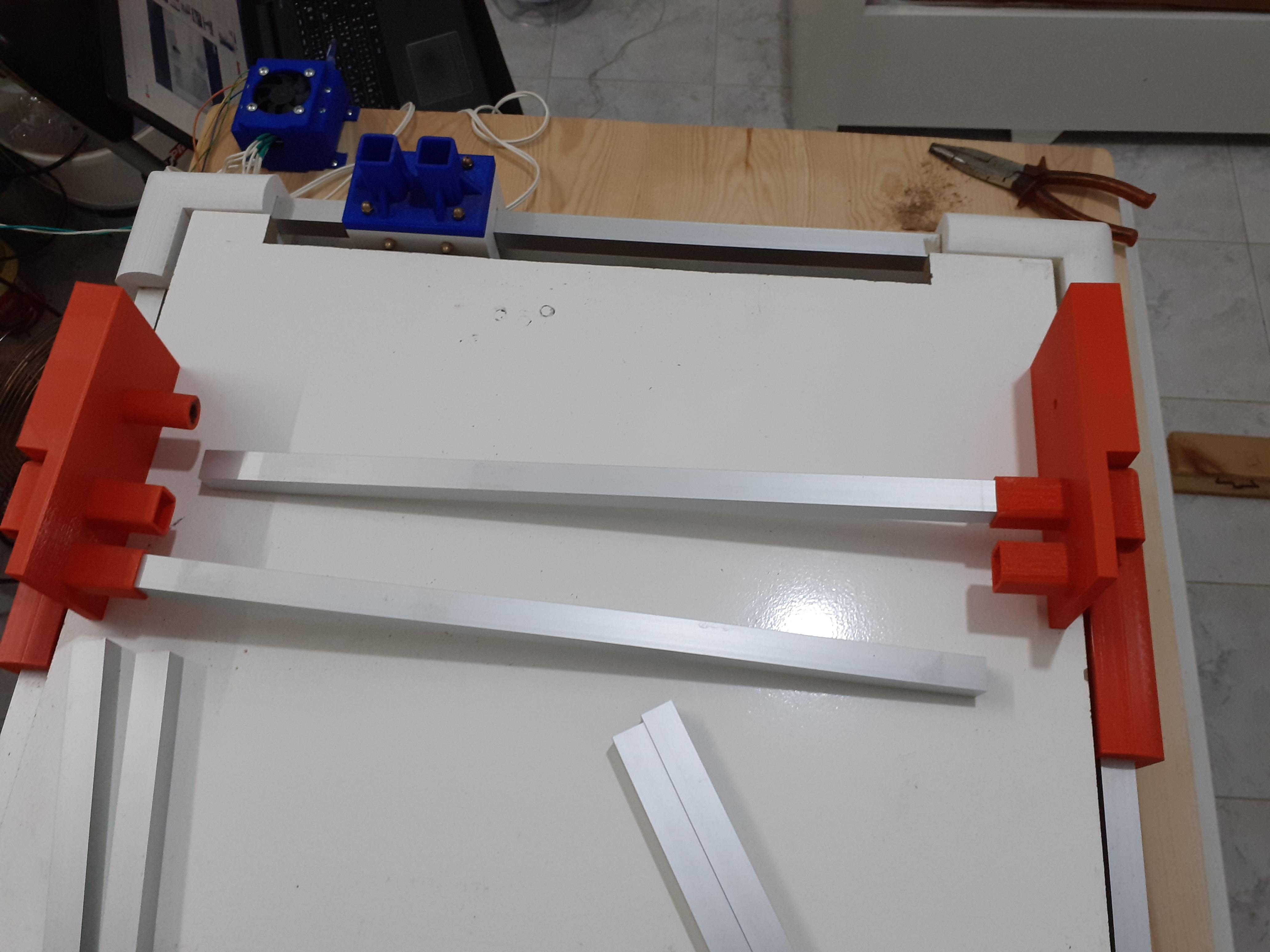
Start by the Base
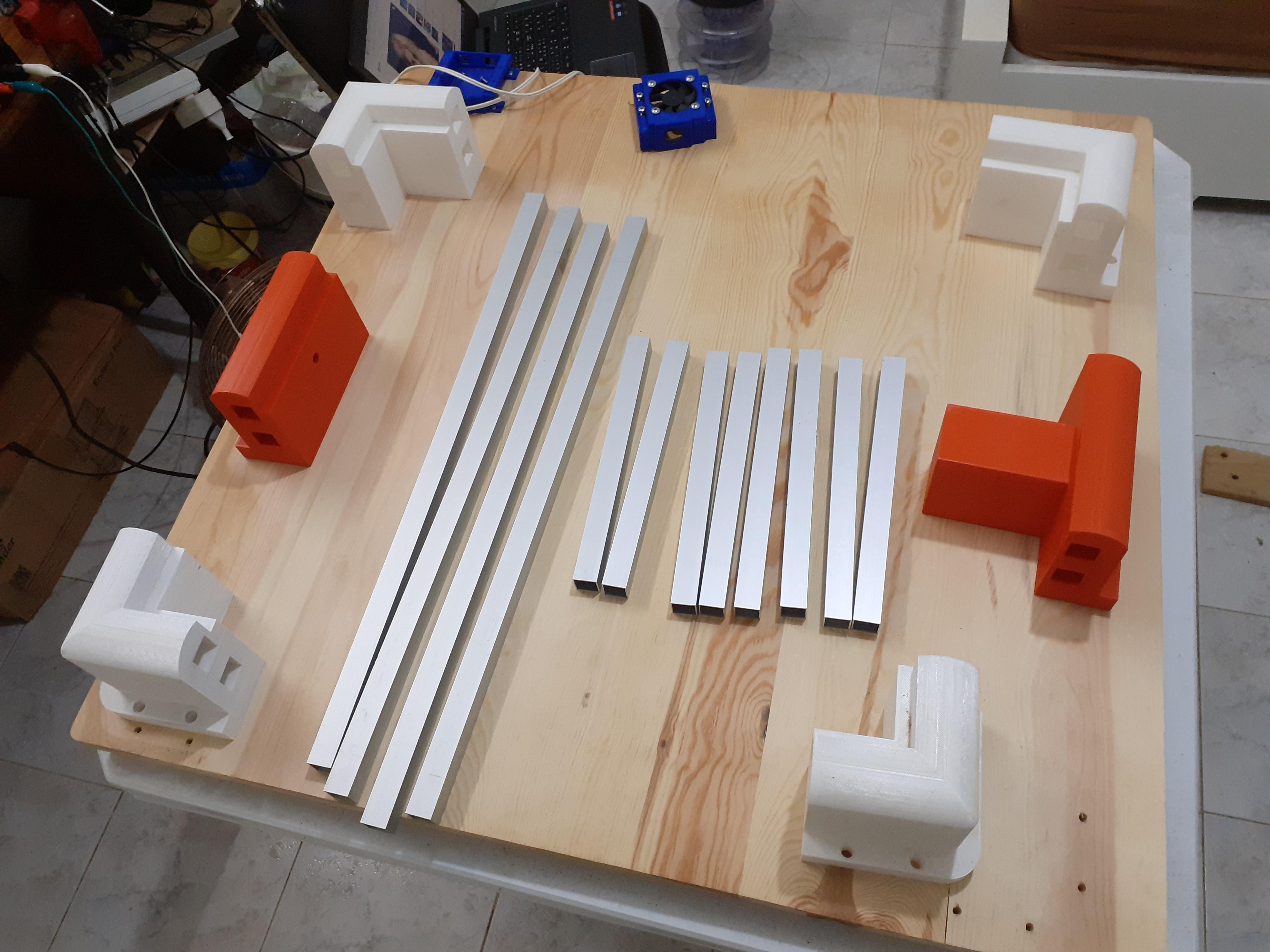
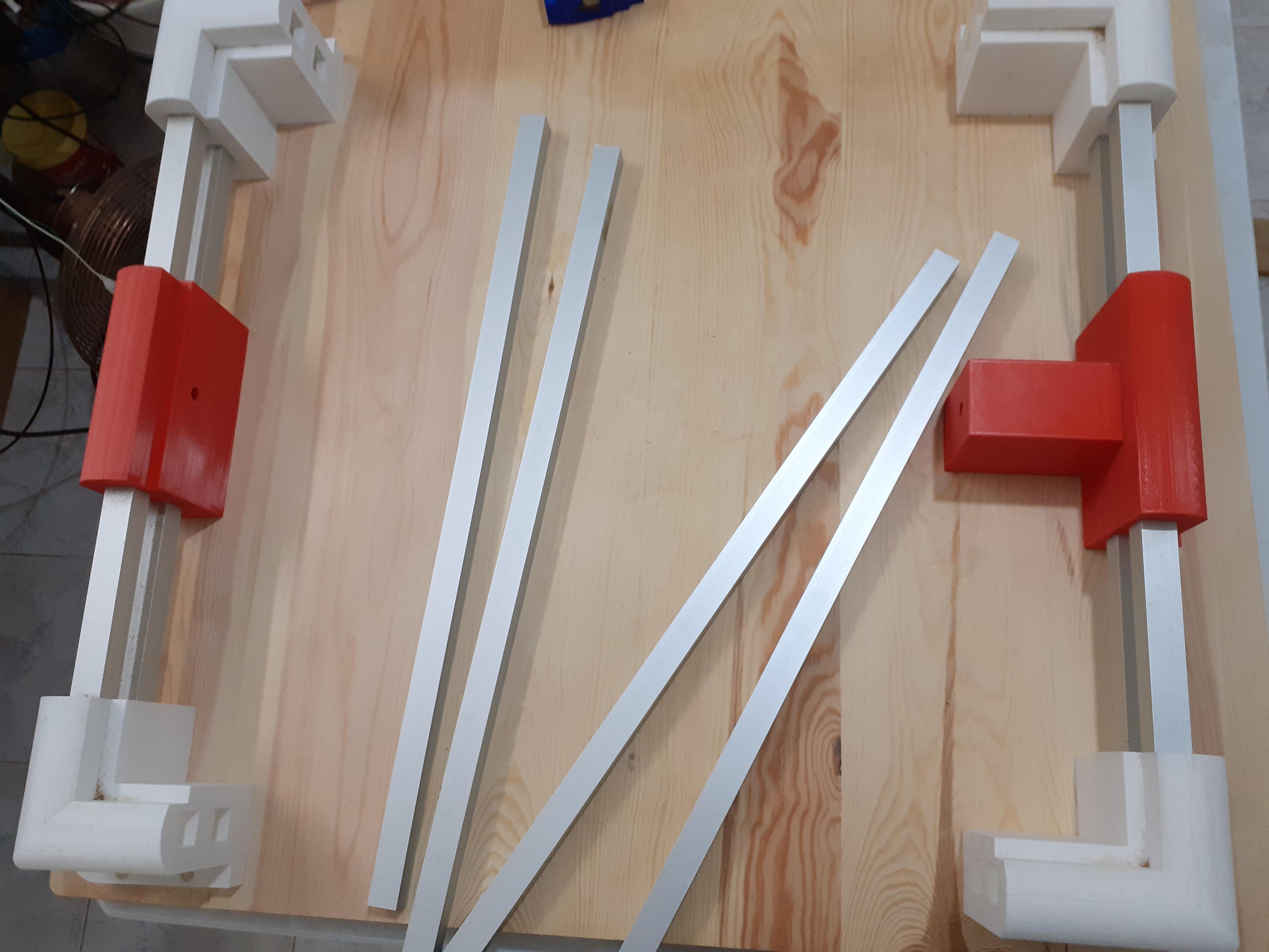
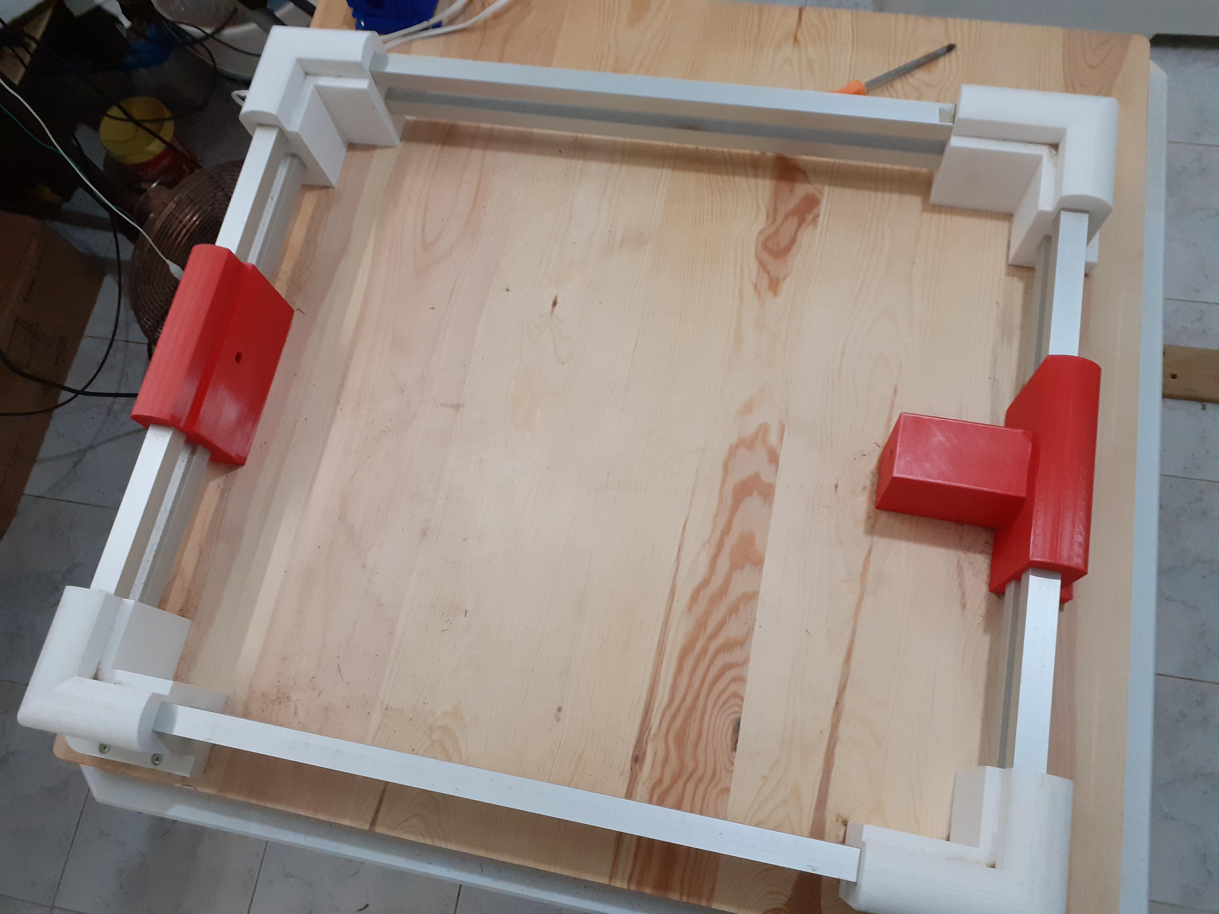
as soon as you finish printing start by the base
- first, cut the square tubes to the right lengths (you can find the right measurements in the design )
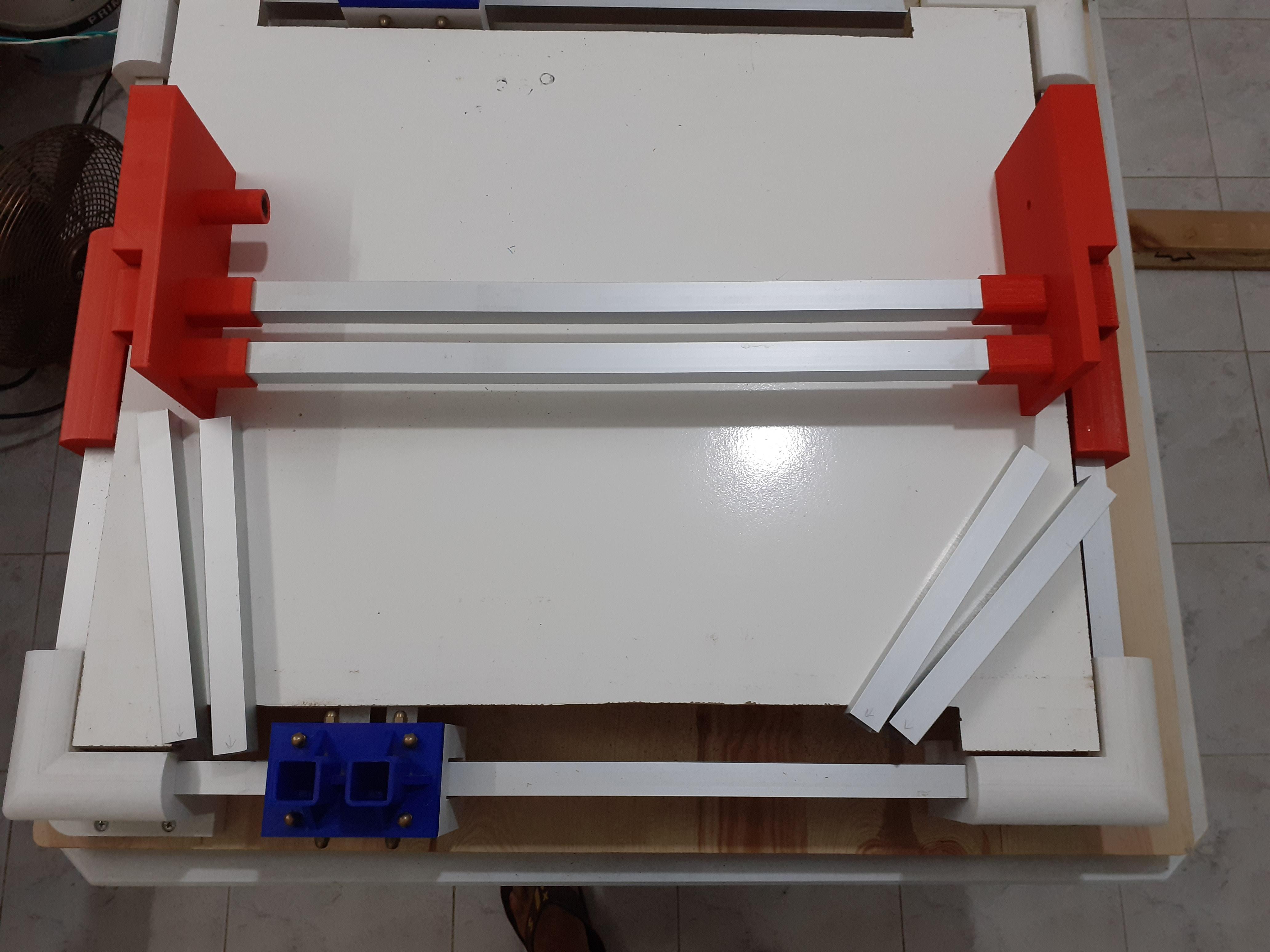
- second, put the tubes into the holes it's easy to mount
- third fix the CNC to the wood board (board dimensions in design also)
and that's it you just finished the hardest part of this machine now get ready to the next step
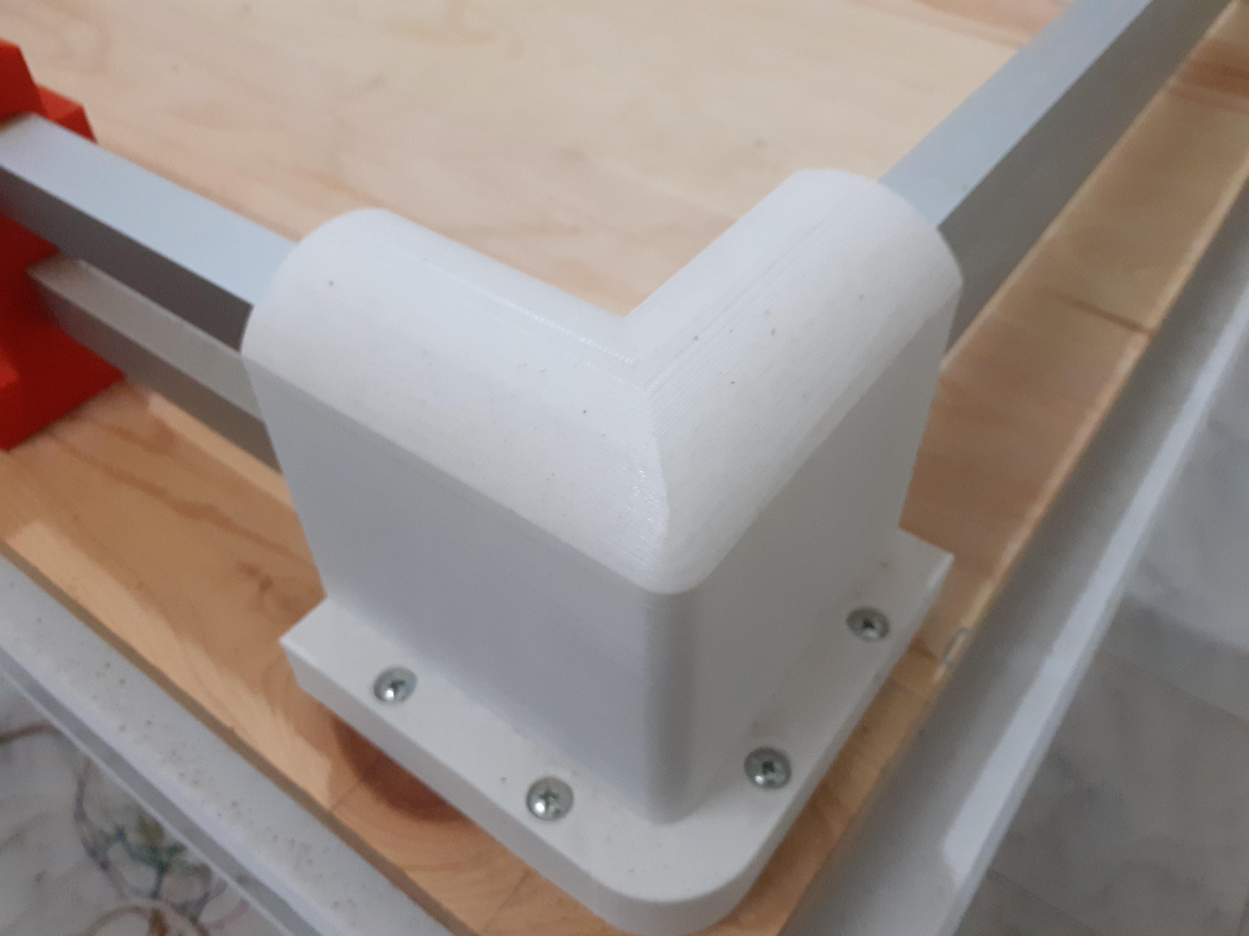
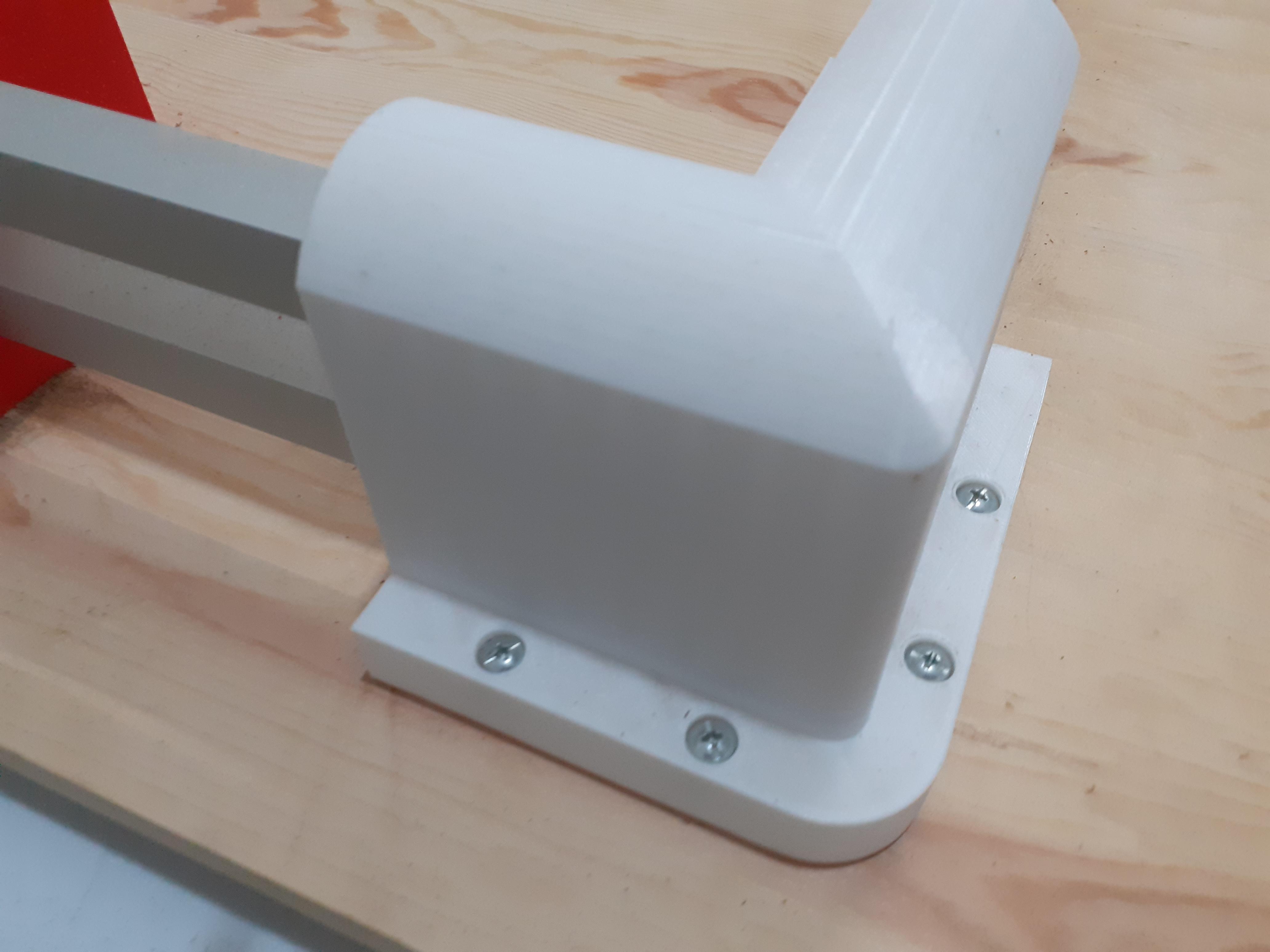
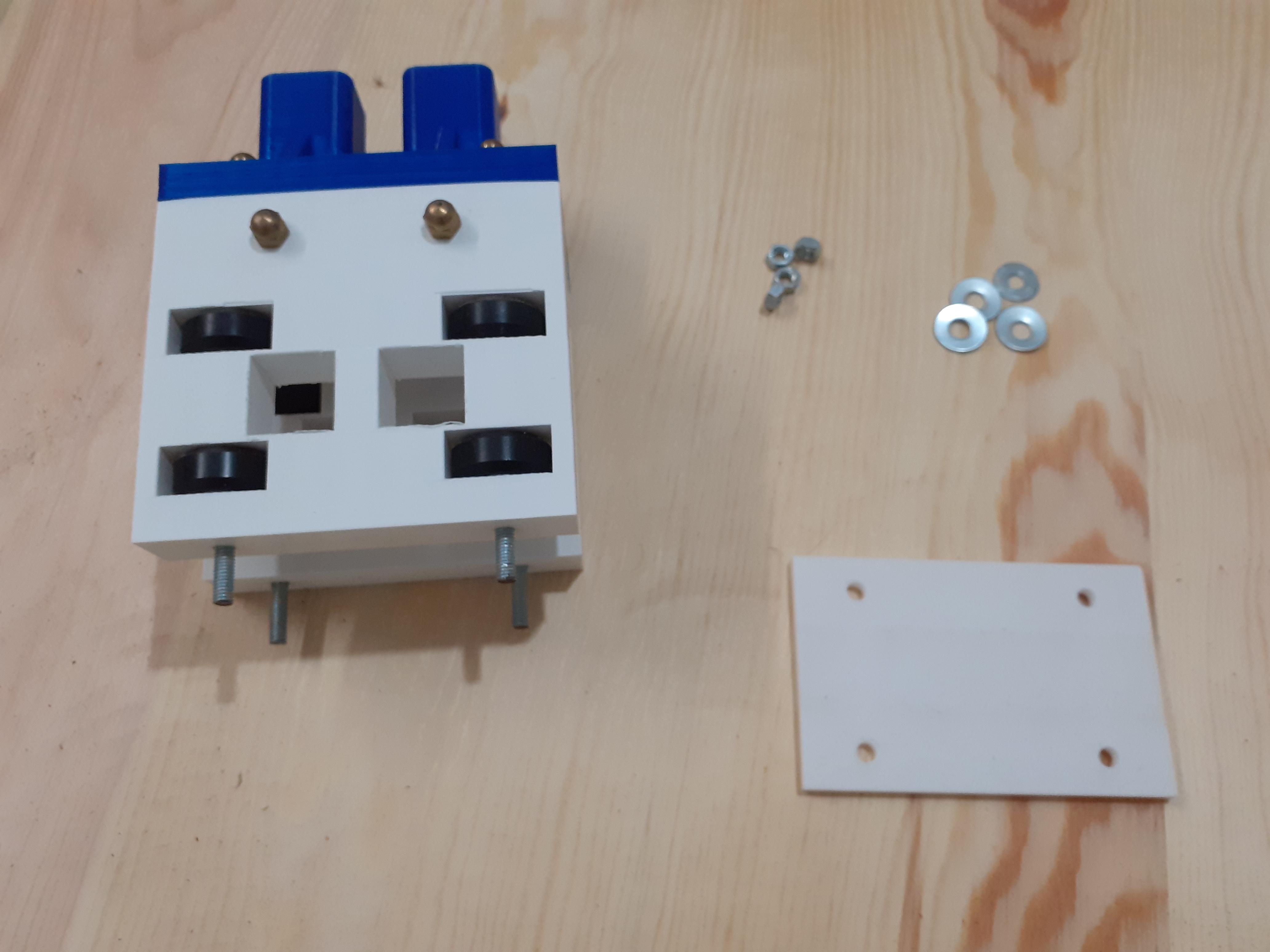
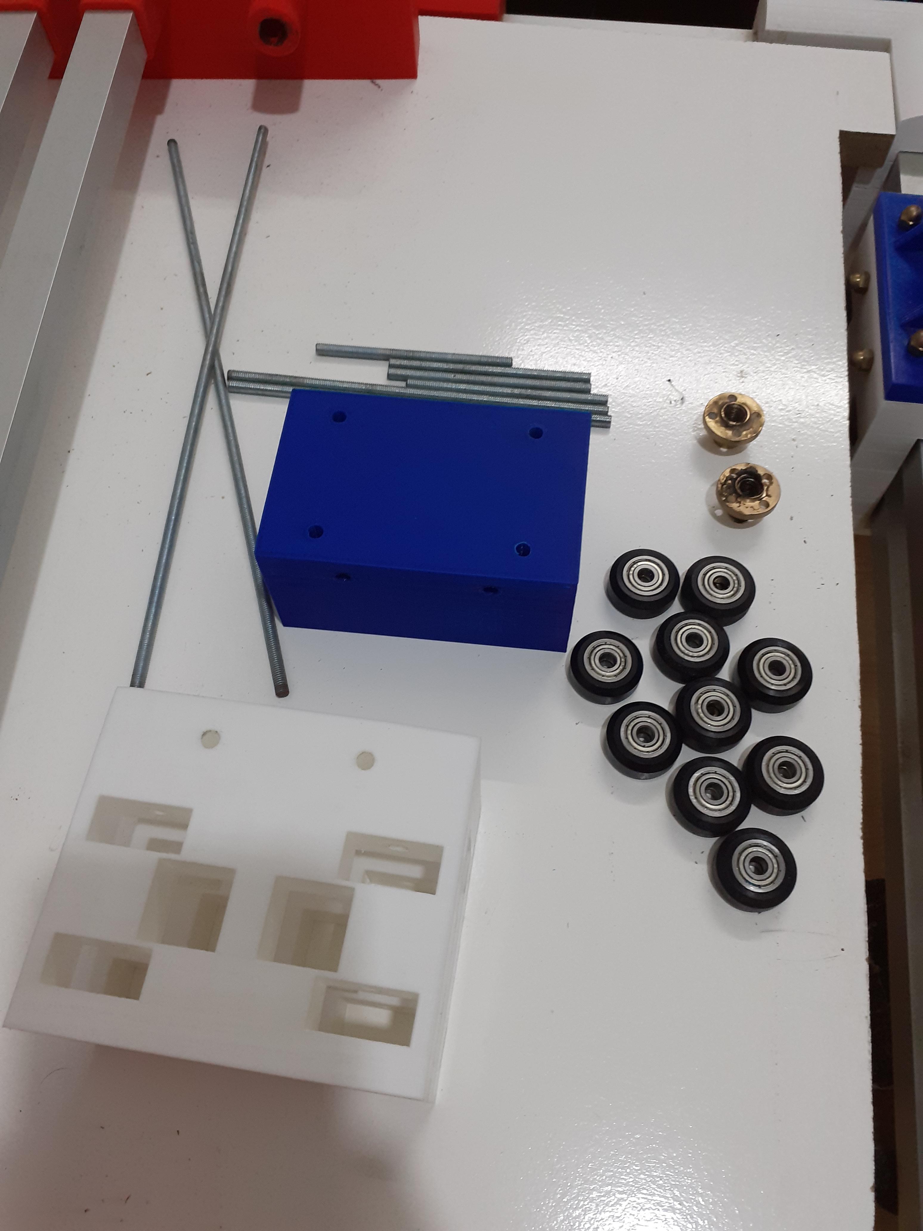
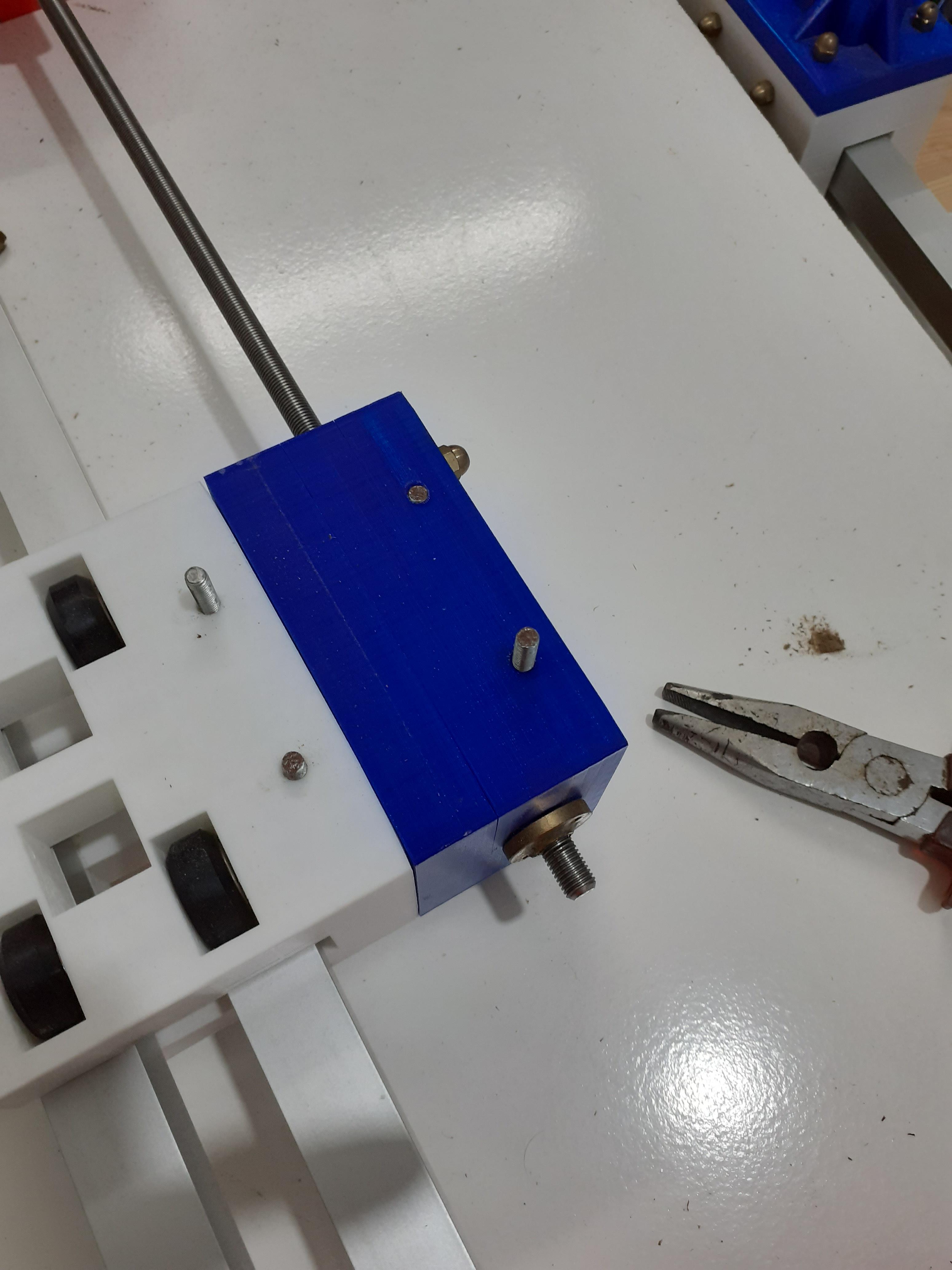
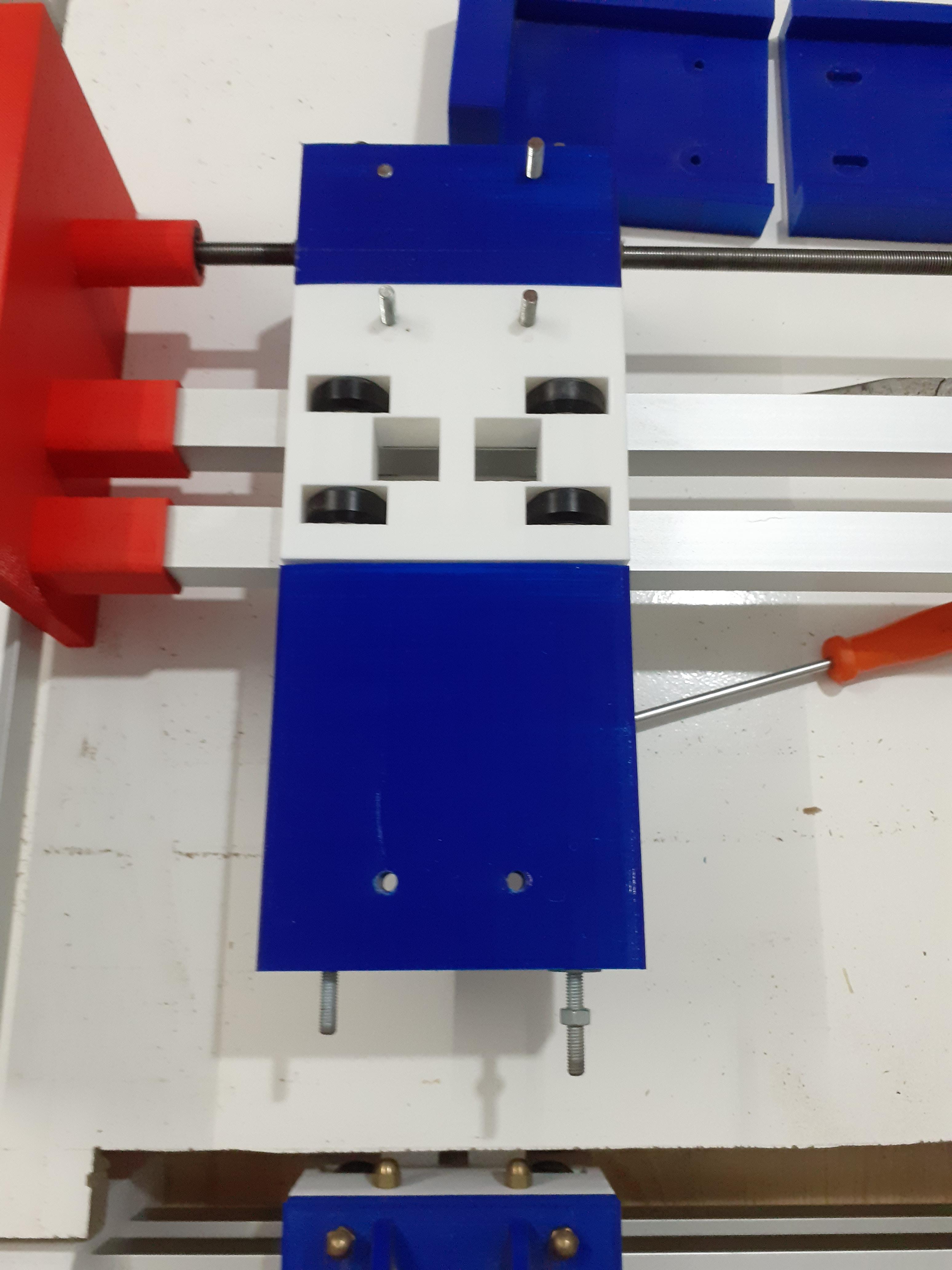
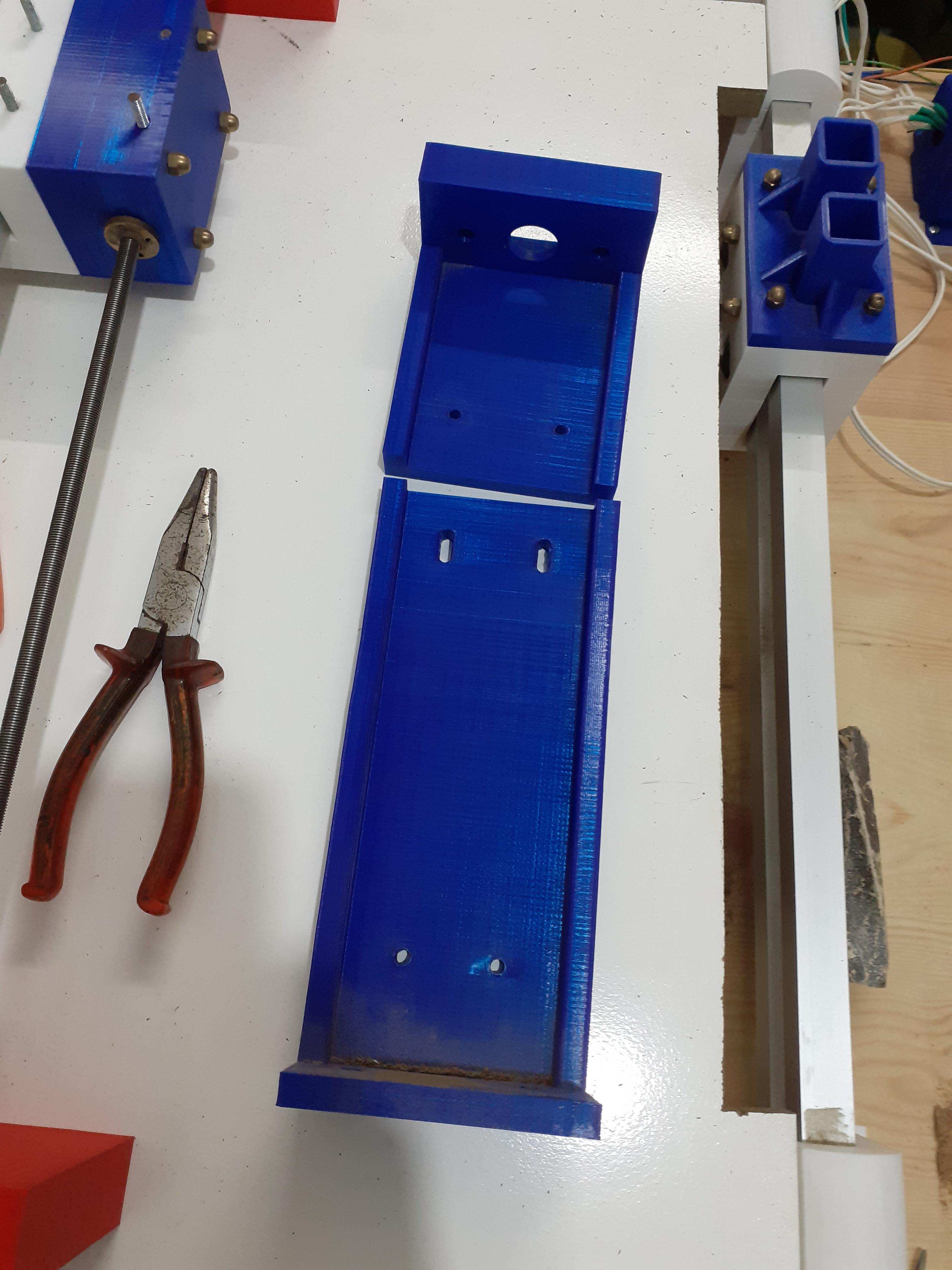
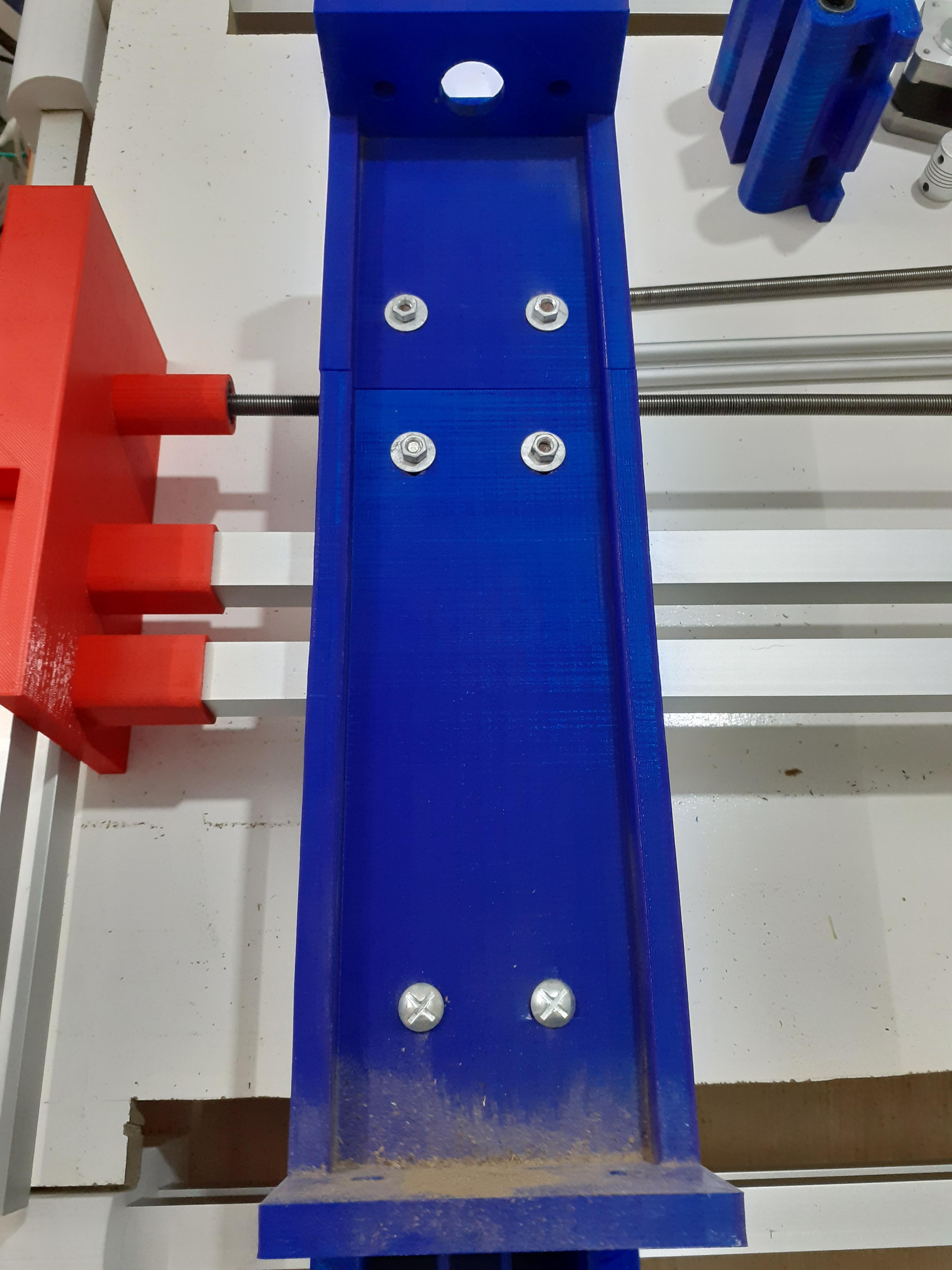
Mount the Side Sliders
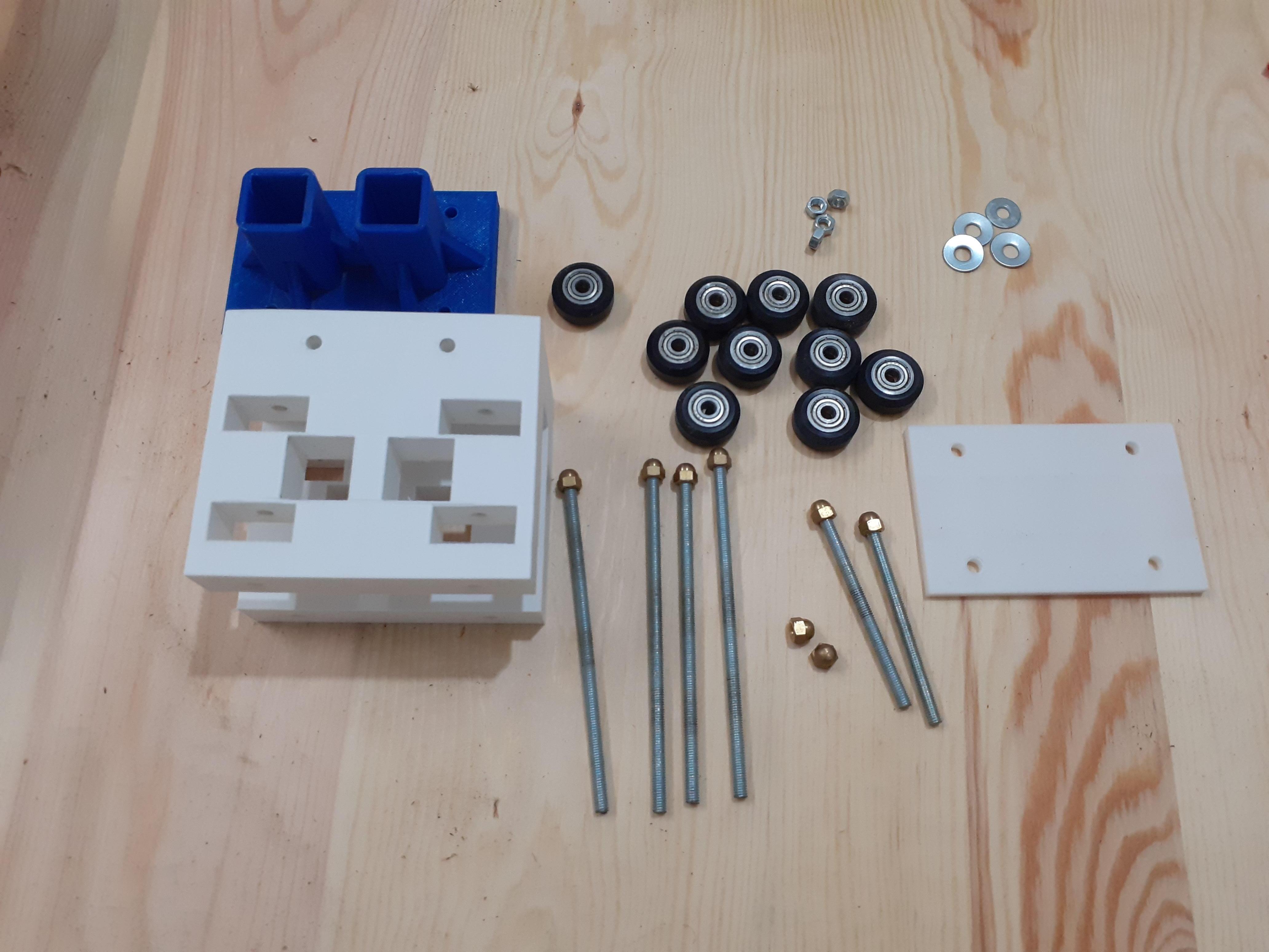
you have to do this step twice because we have two sliders on the sides but it's very easy to build
- get your bearings, nuts, and the 5 mm threaded rod (measurement in design )
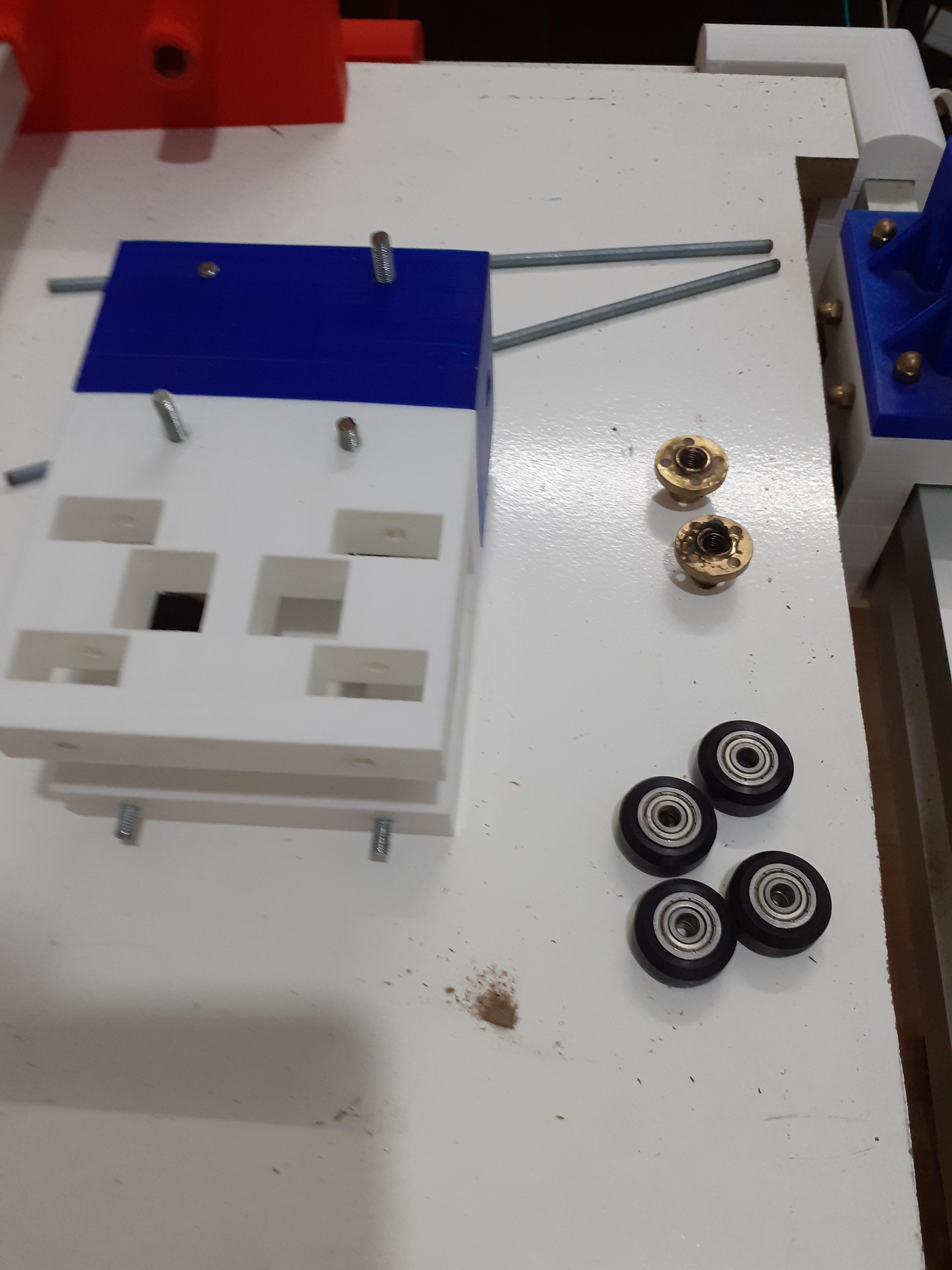
- put the bearing in the rectangle holes and attach them with the threaded rod from the holes above
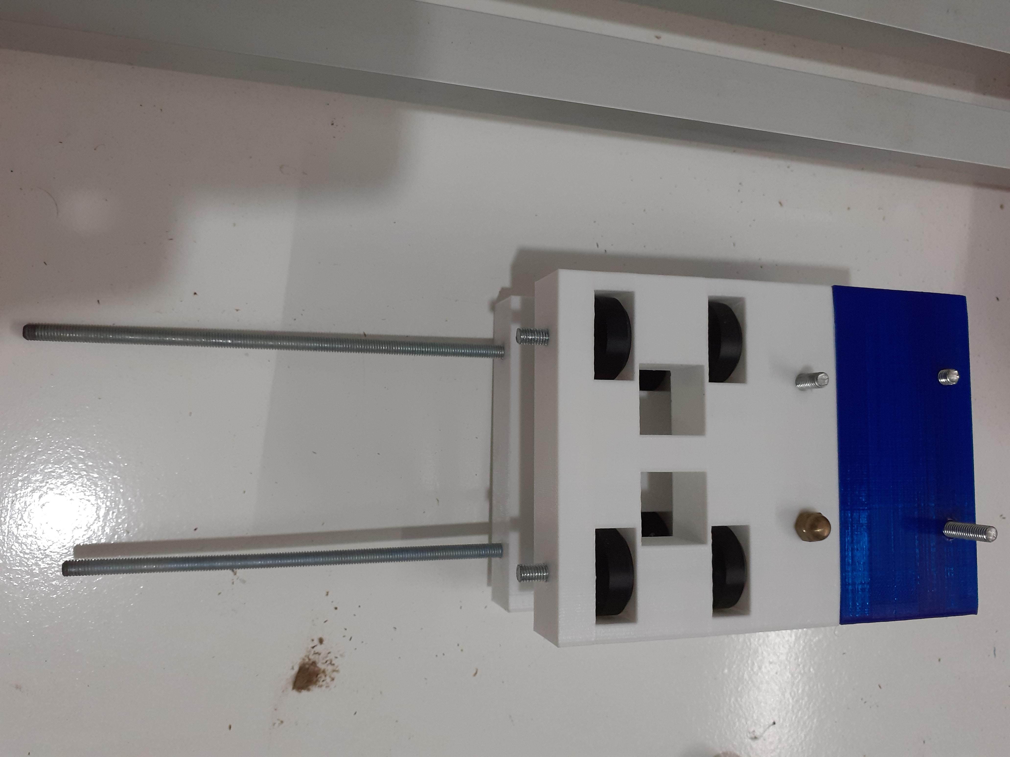
- attach the blue piece to cover the upper bearings and it will also hold the rest of the machine
- before putting the bottom cover put the slider on square tubes and then close them and test if it's sliding smoothly
that's it you're getting there one more step for the base
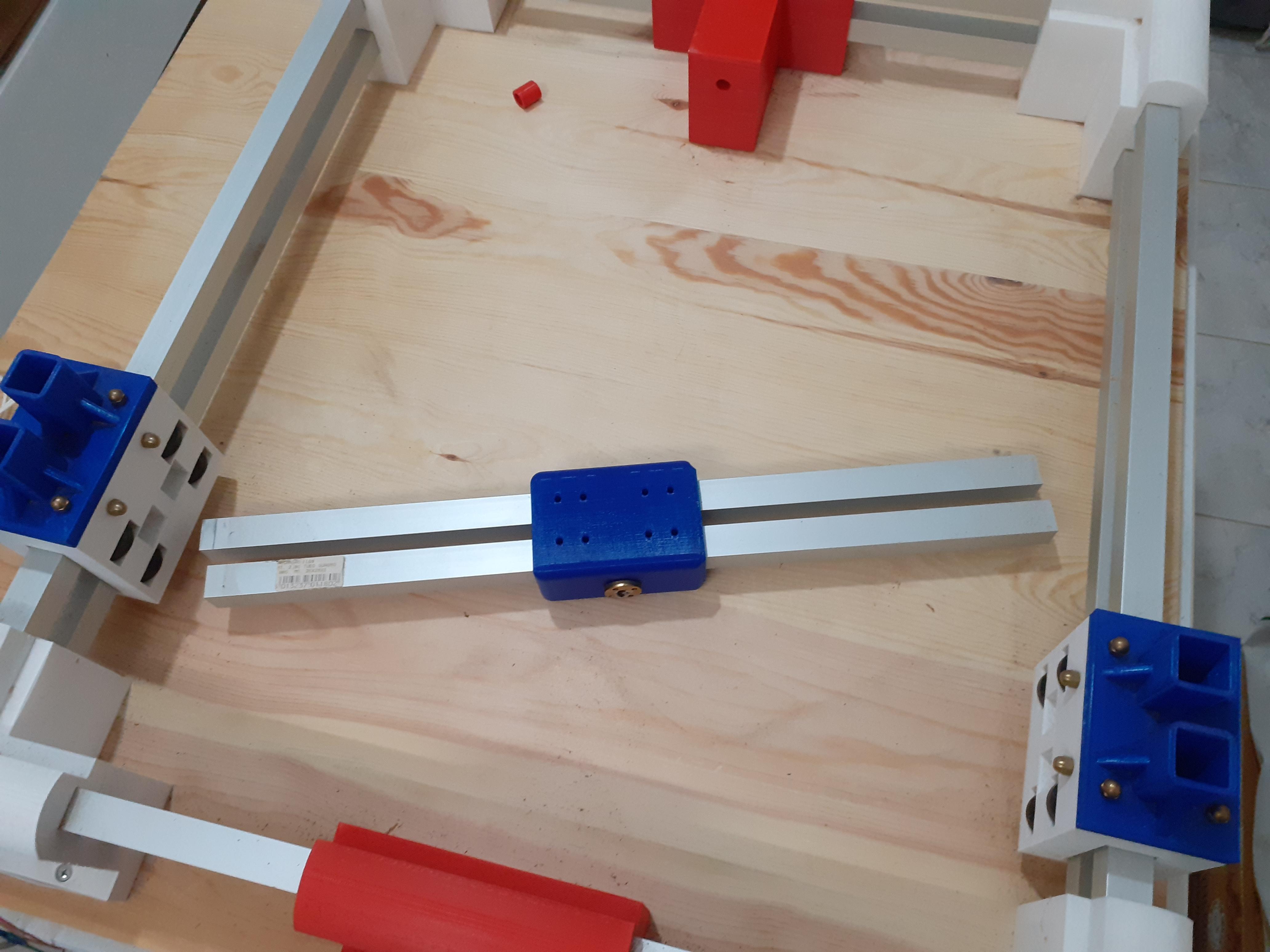
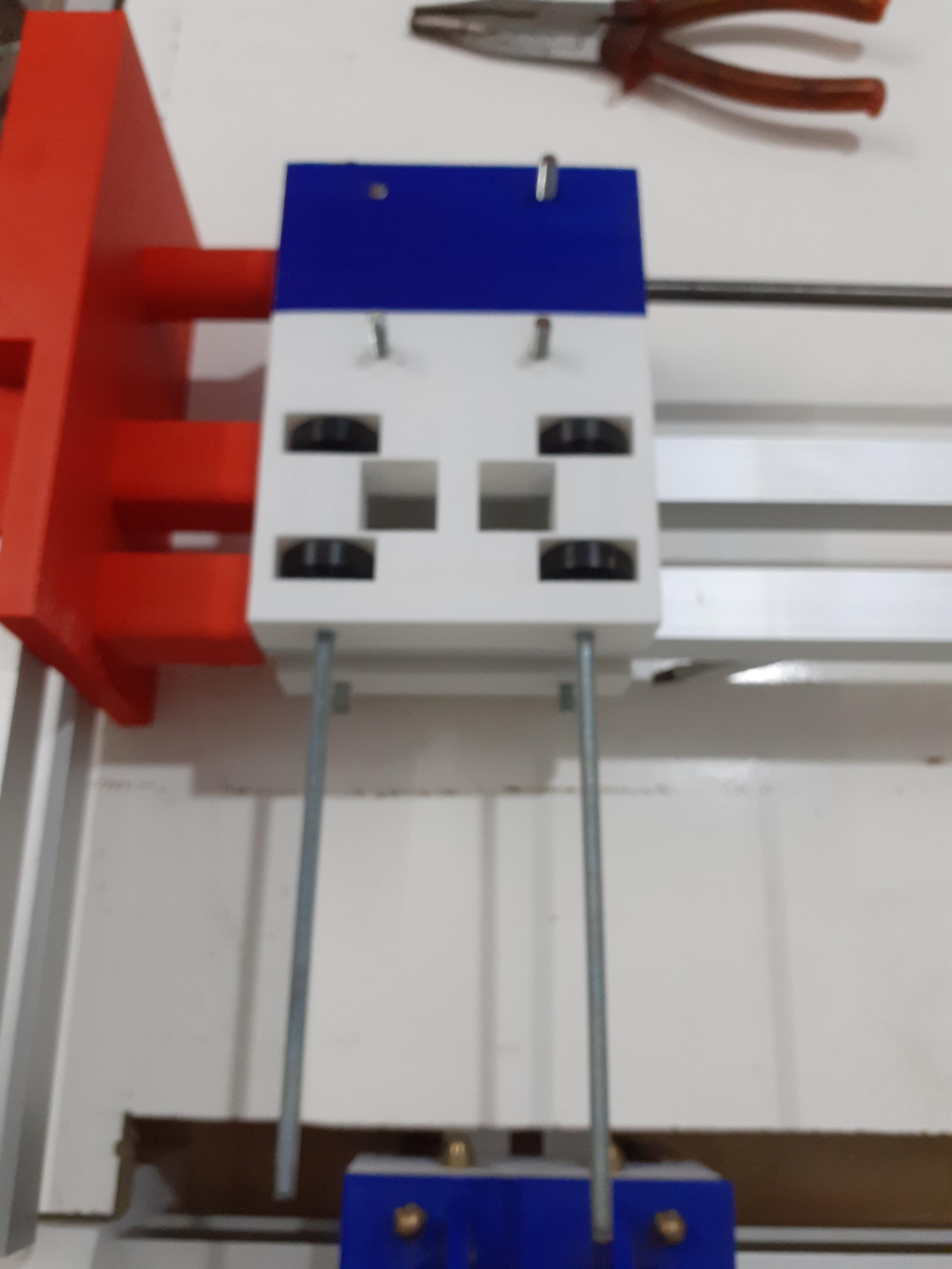
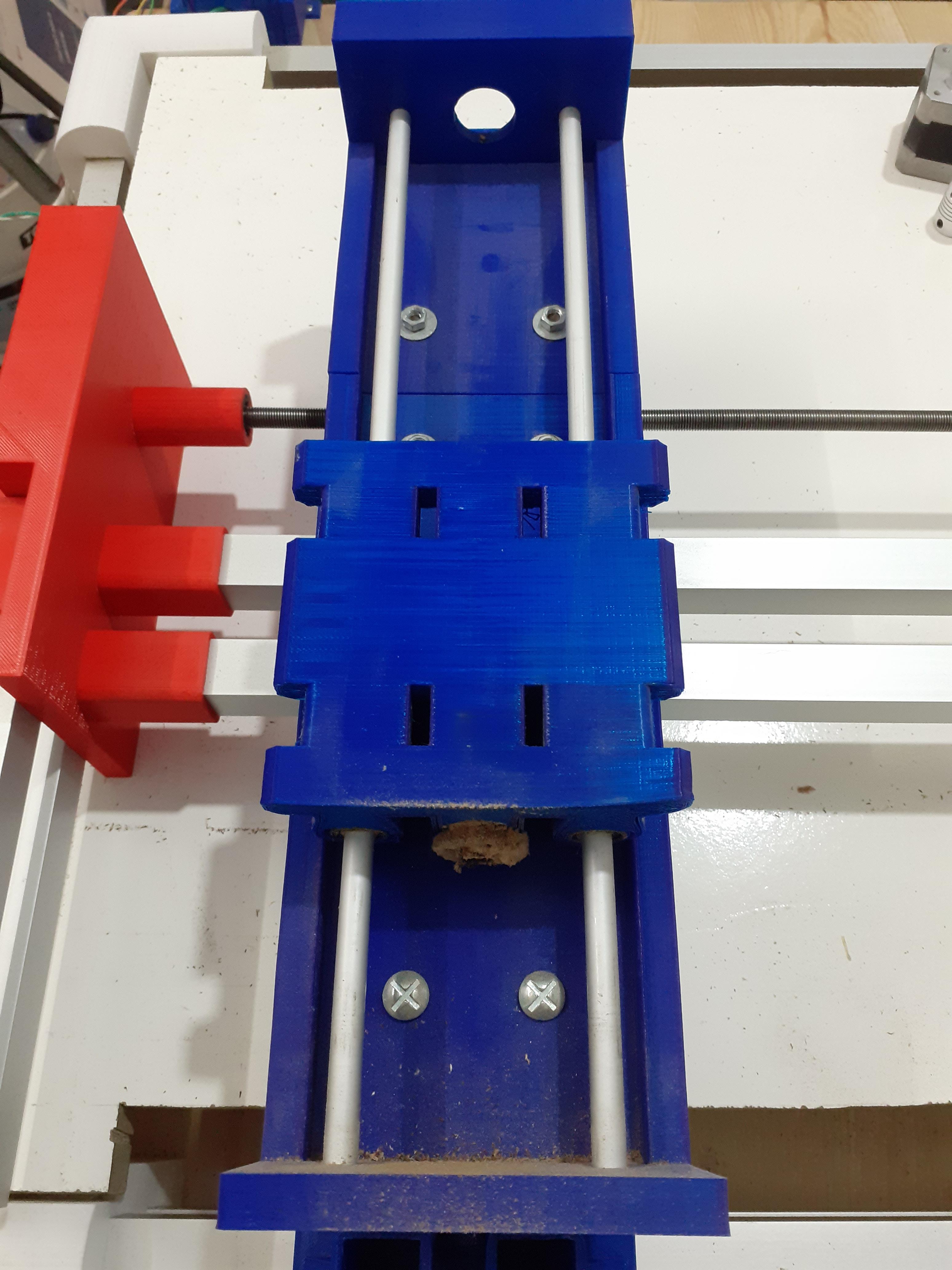
Mount the Connector Between the Two Sliders
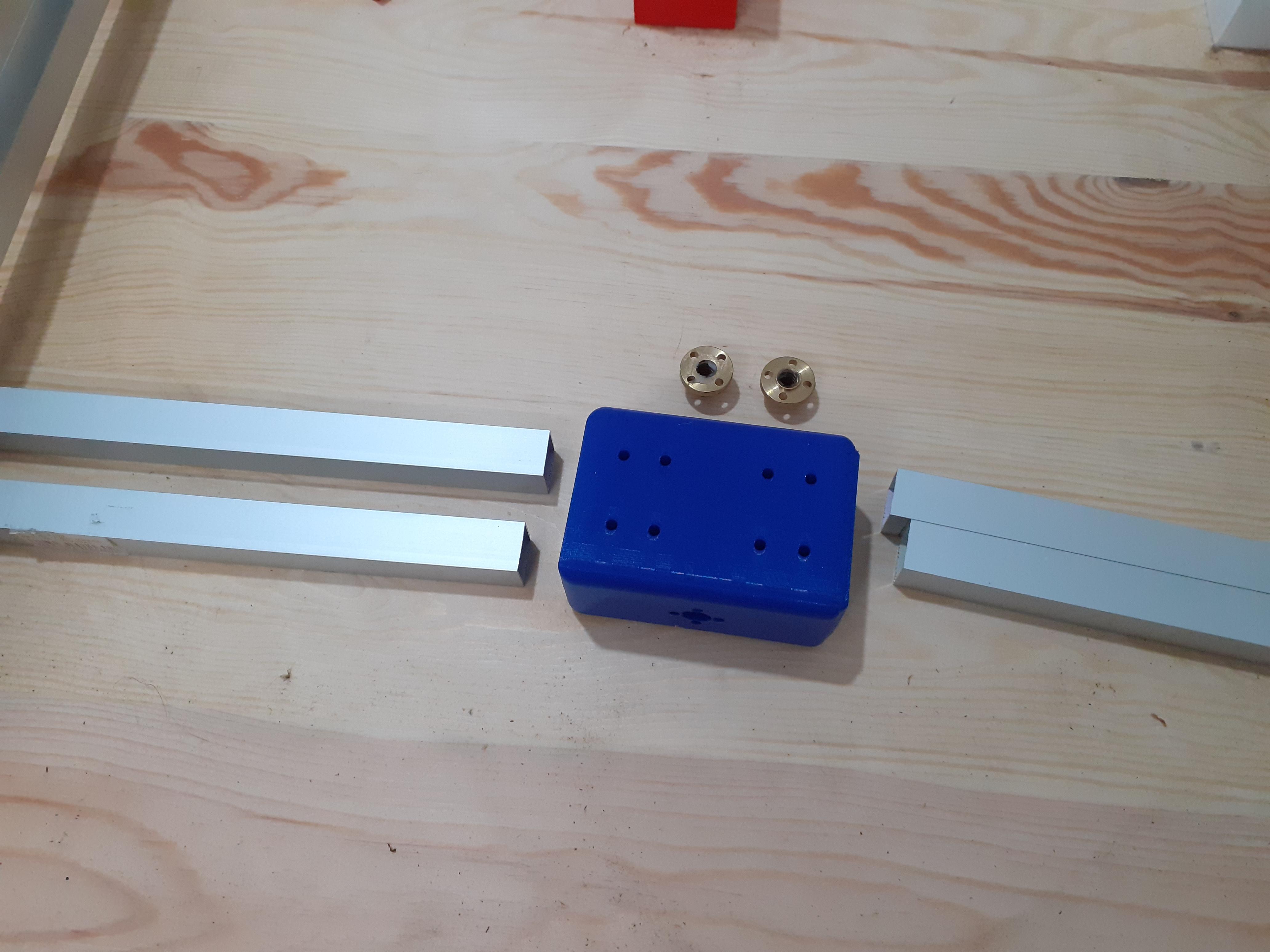

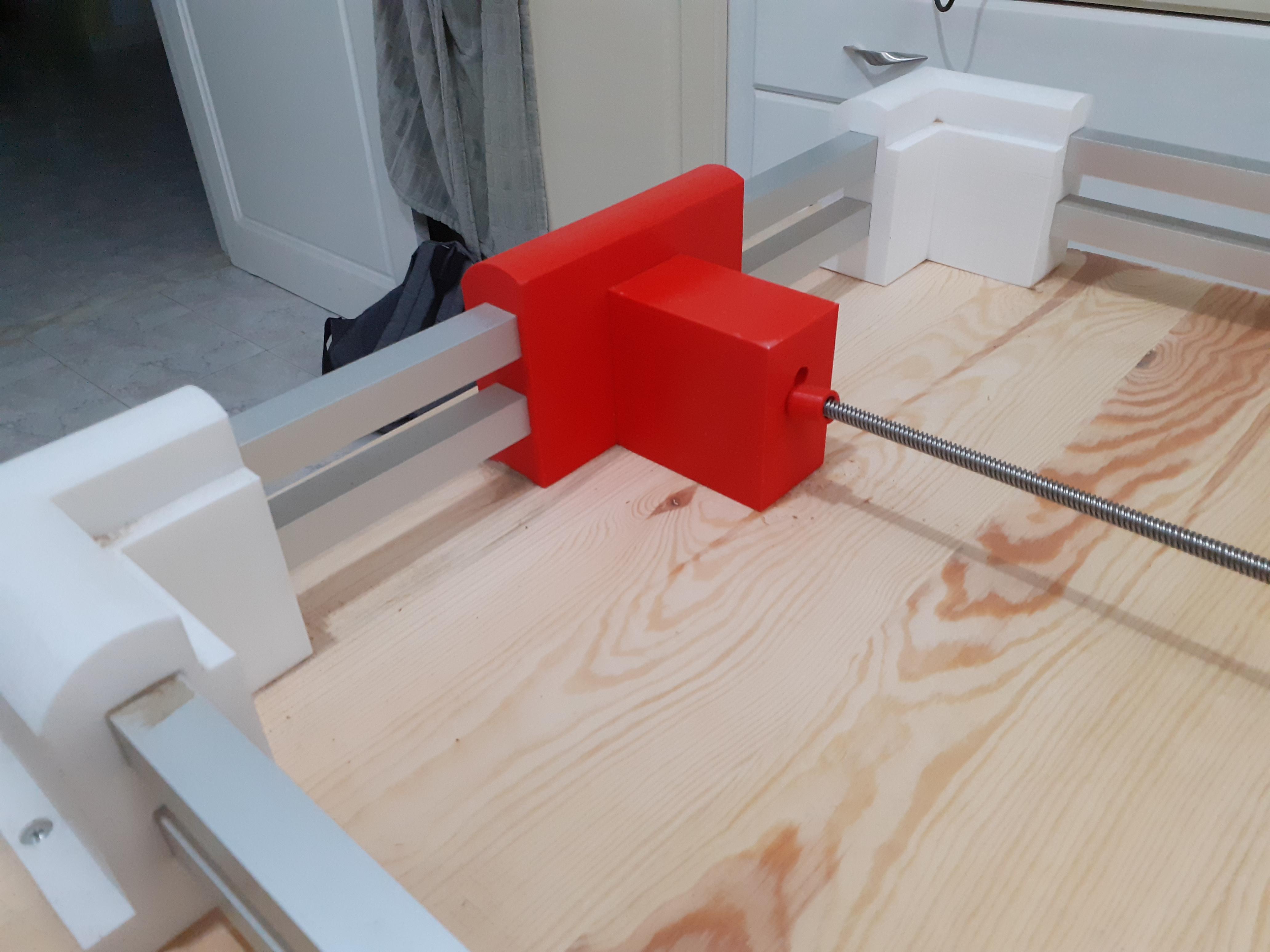
in order for the sliders to move they need to be connected to move at the same time
so take that blue piece and insert the 4 square tubes into their places (square tube lengths found in design)
and insert the nuts for the leading screw so it can move the X-axis
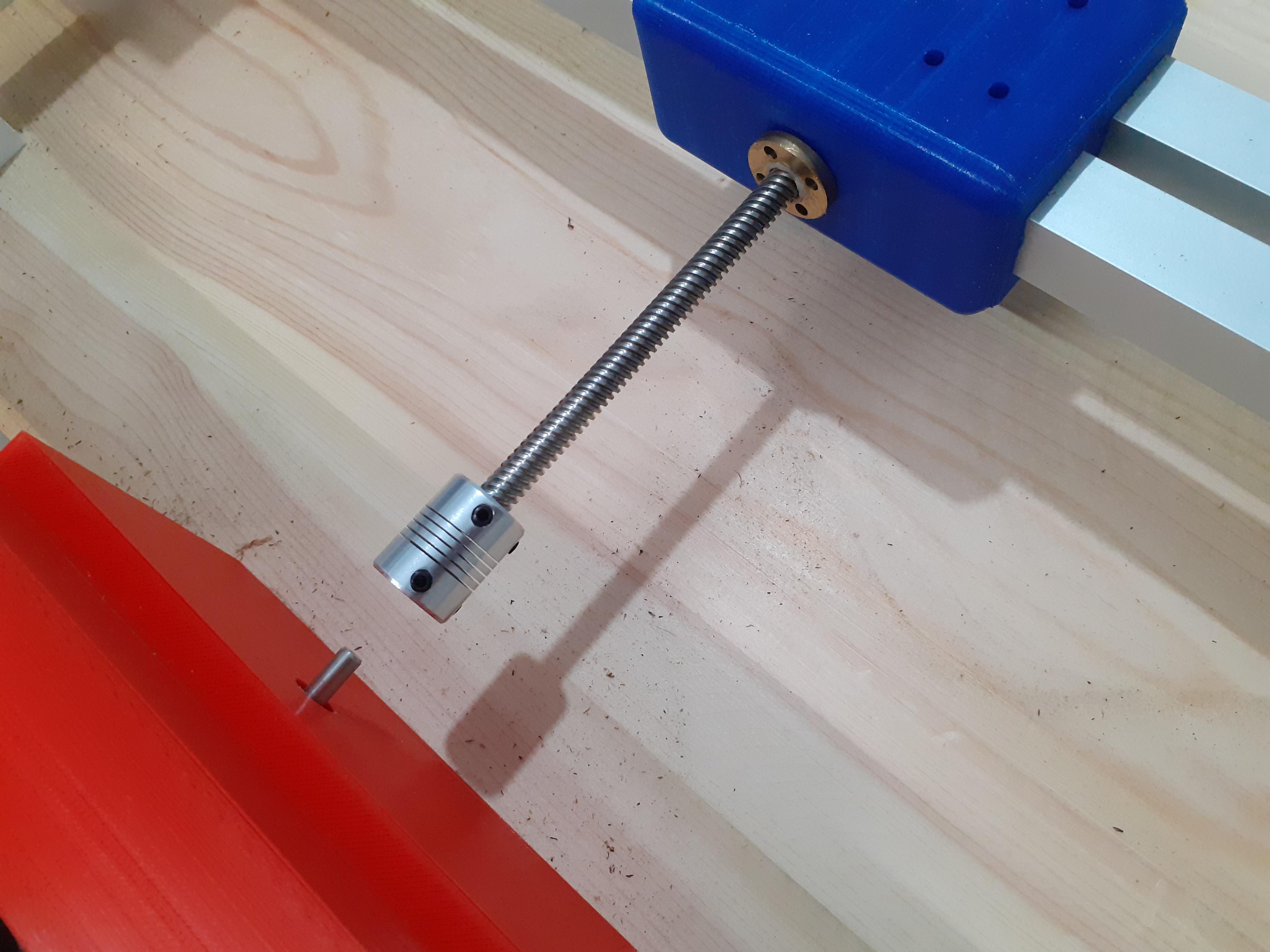
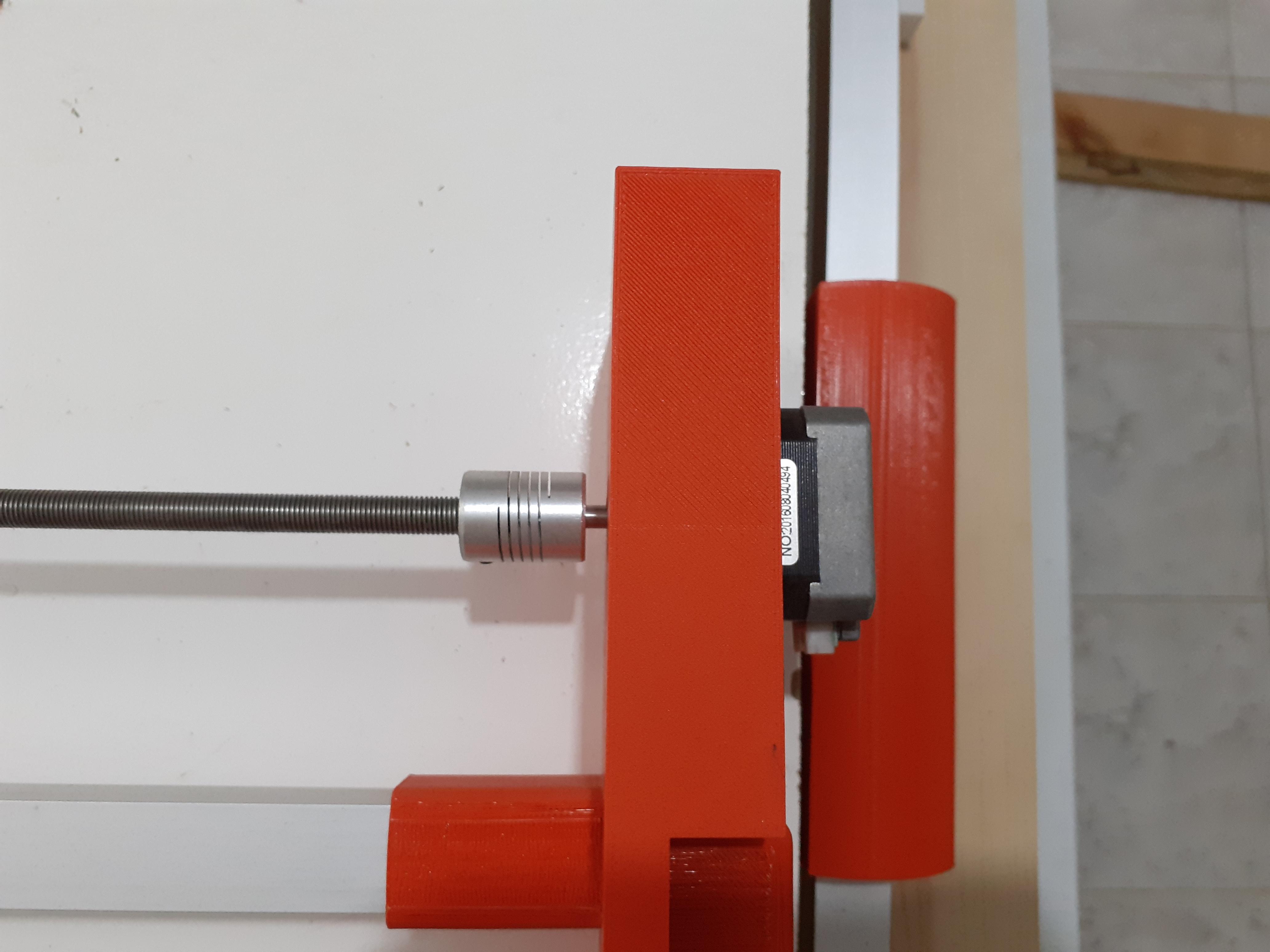
connect the leading screw and the motor with the help of a coupling
and by this, we just finished the base and the X-axis
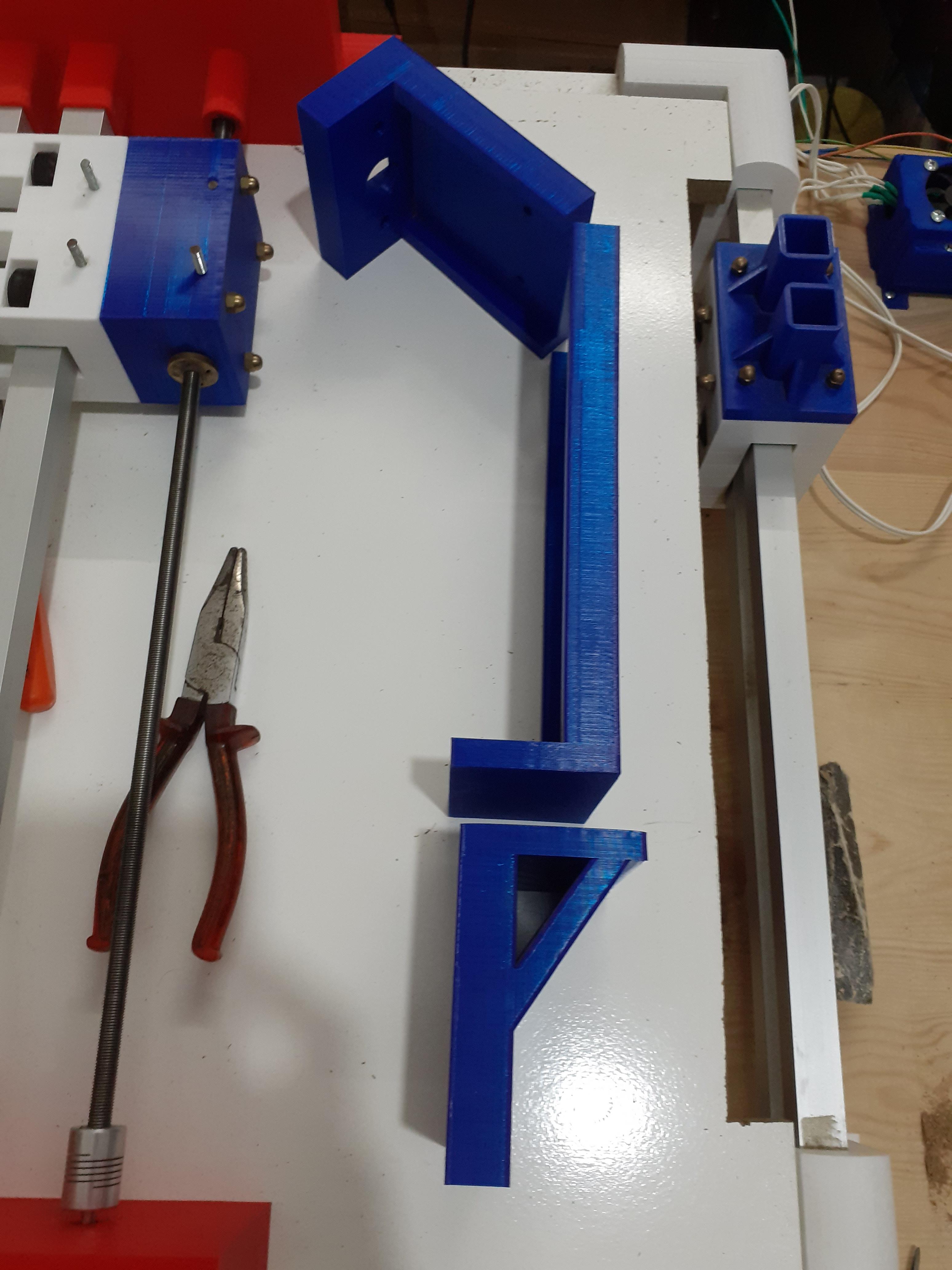
Now we go to the Y-axis
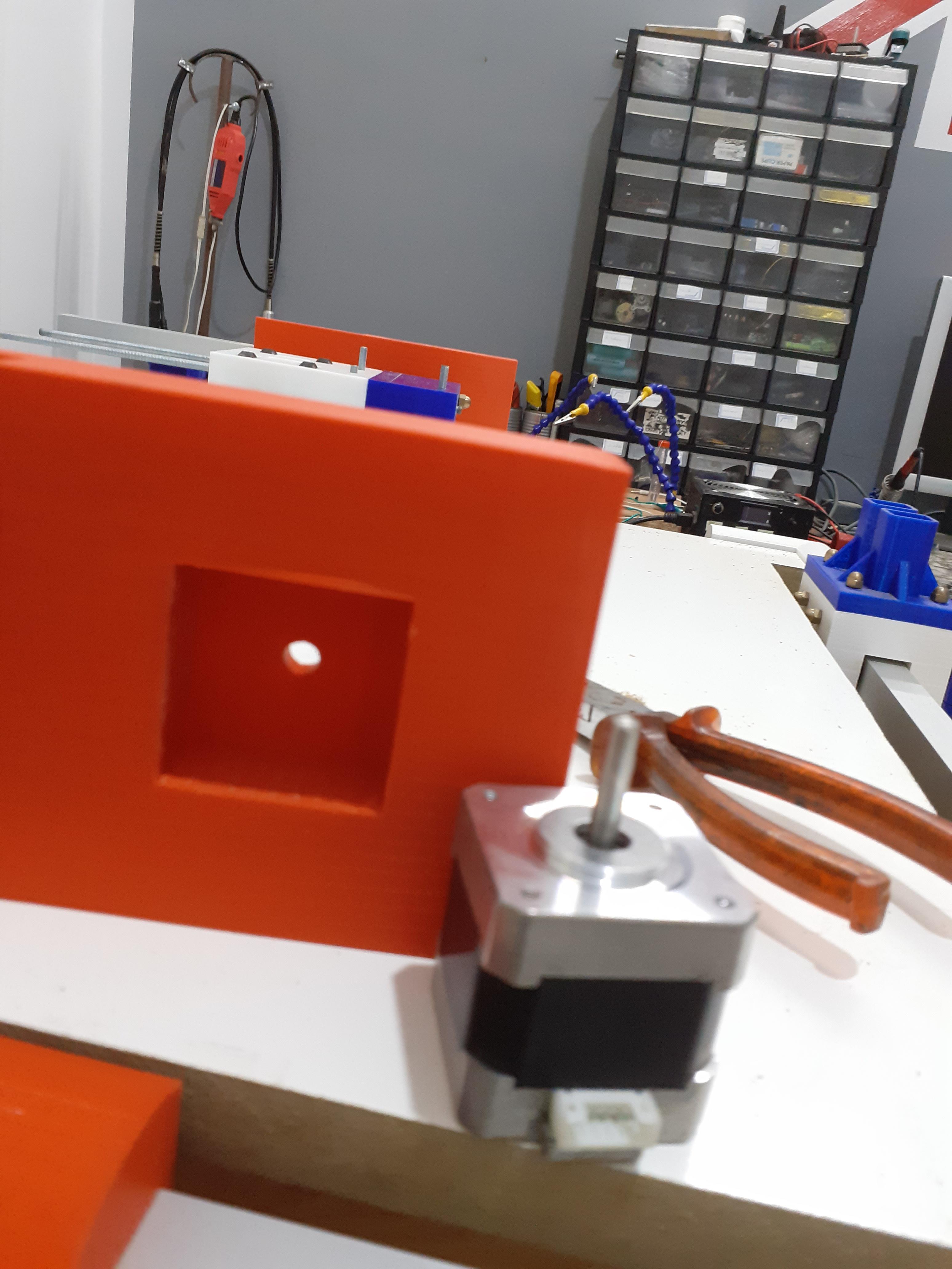
Mount the Base of the Y-axis
after finishing the base and the X-axis we need to mount the base for the Y-axis for that
- bring the needed parts
- cut the square tubes to the right lengths (dimensions in design)
- put the square tubes into the right holes
that's it ....the Y-axis base is finished
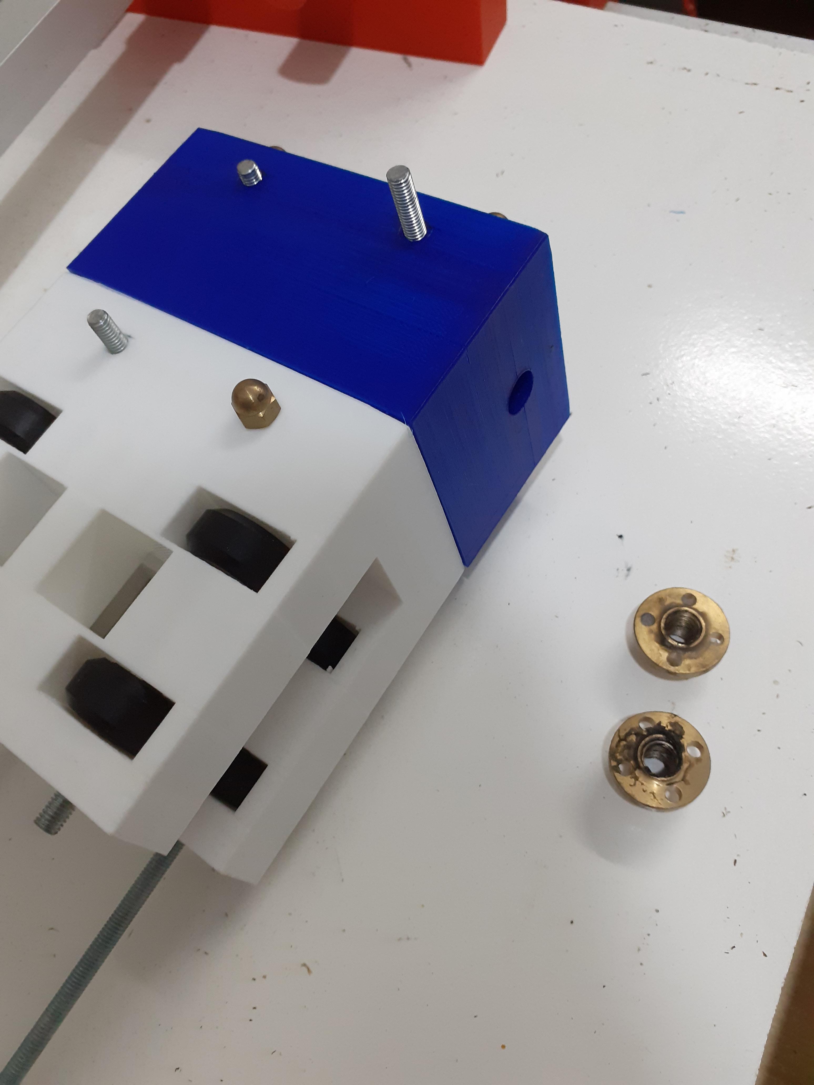
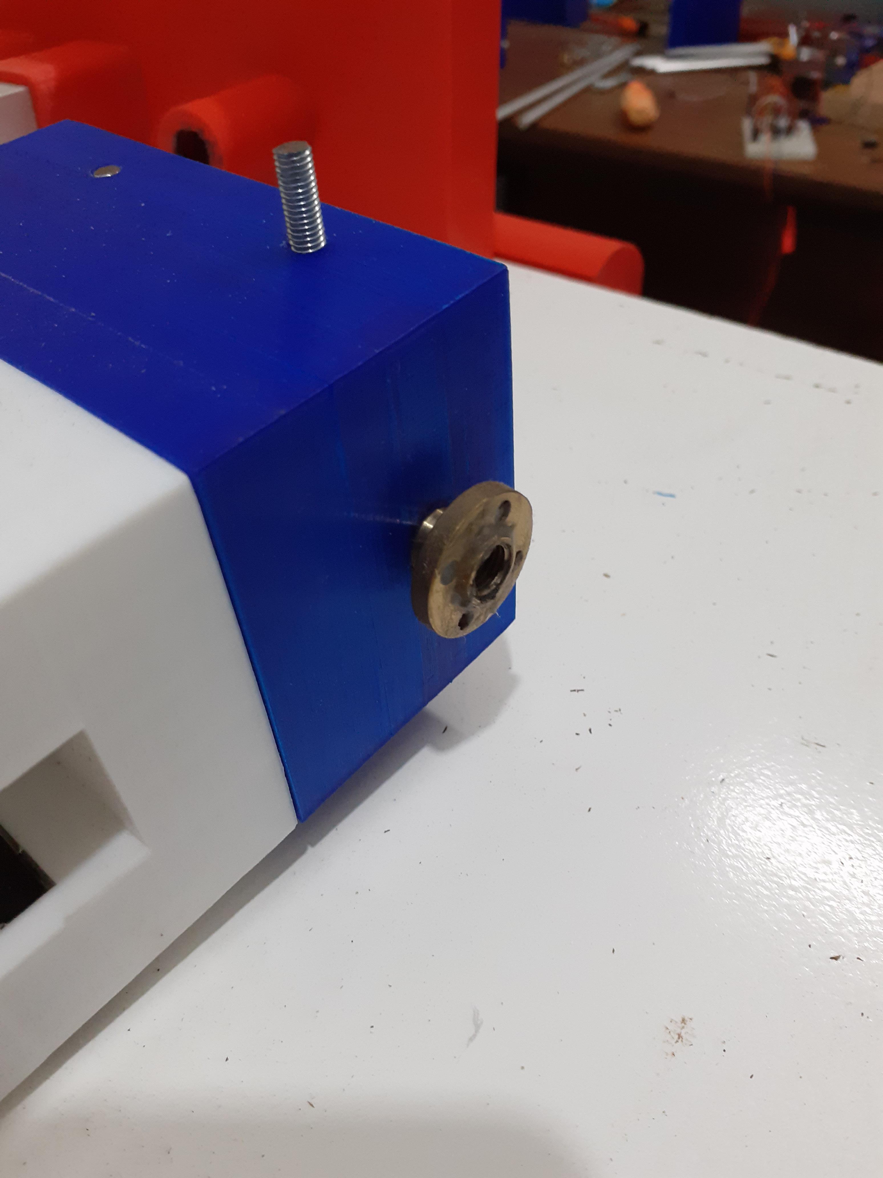
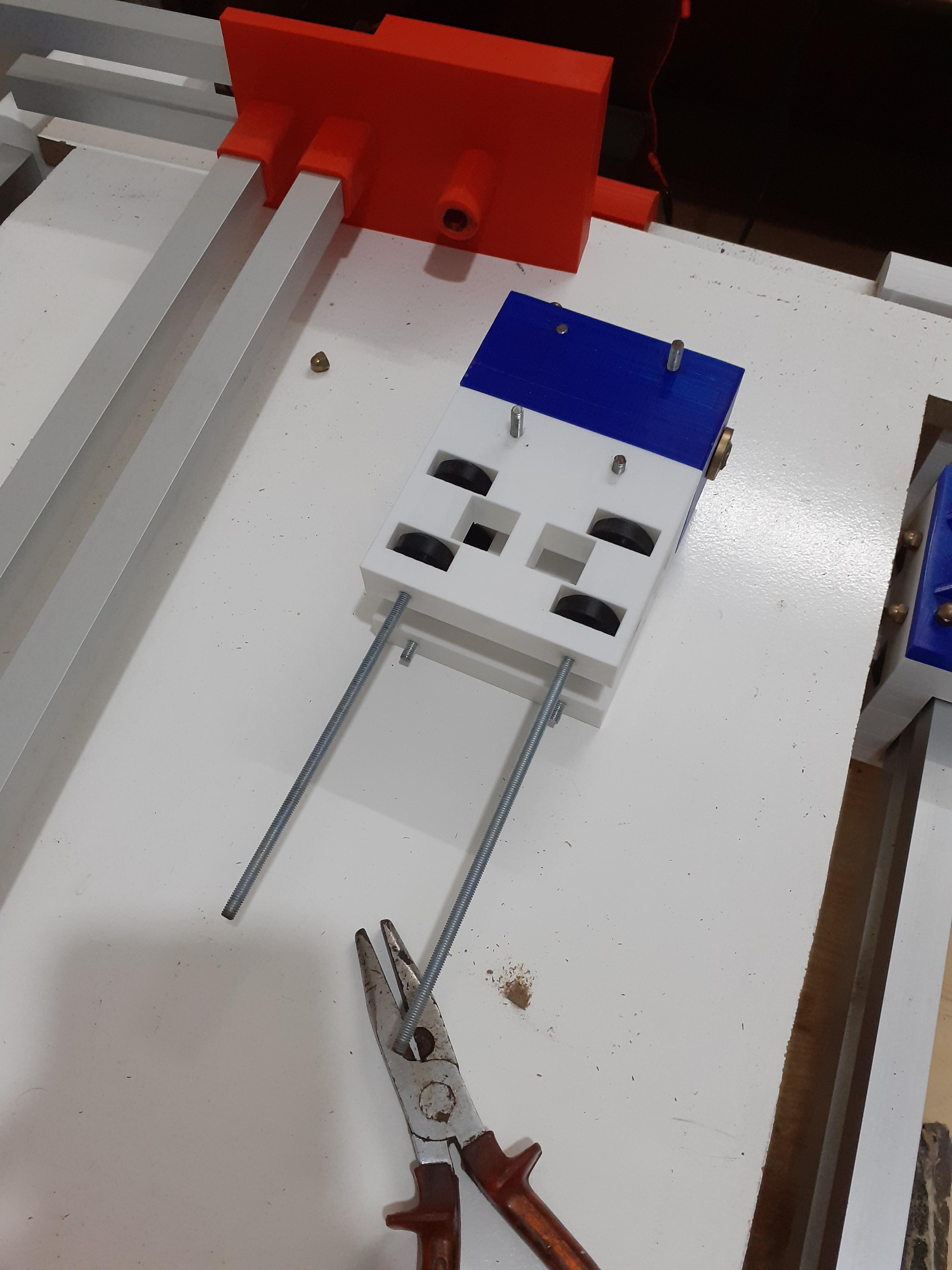
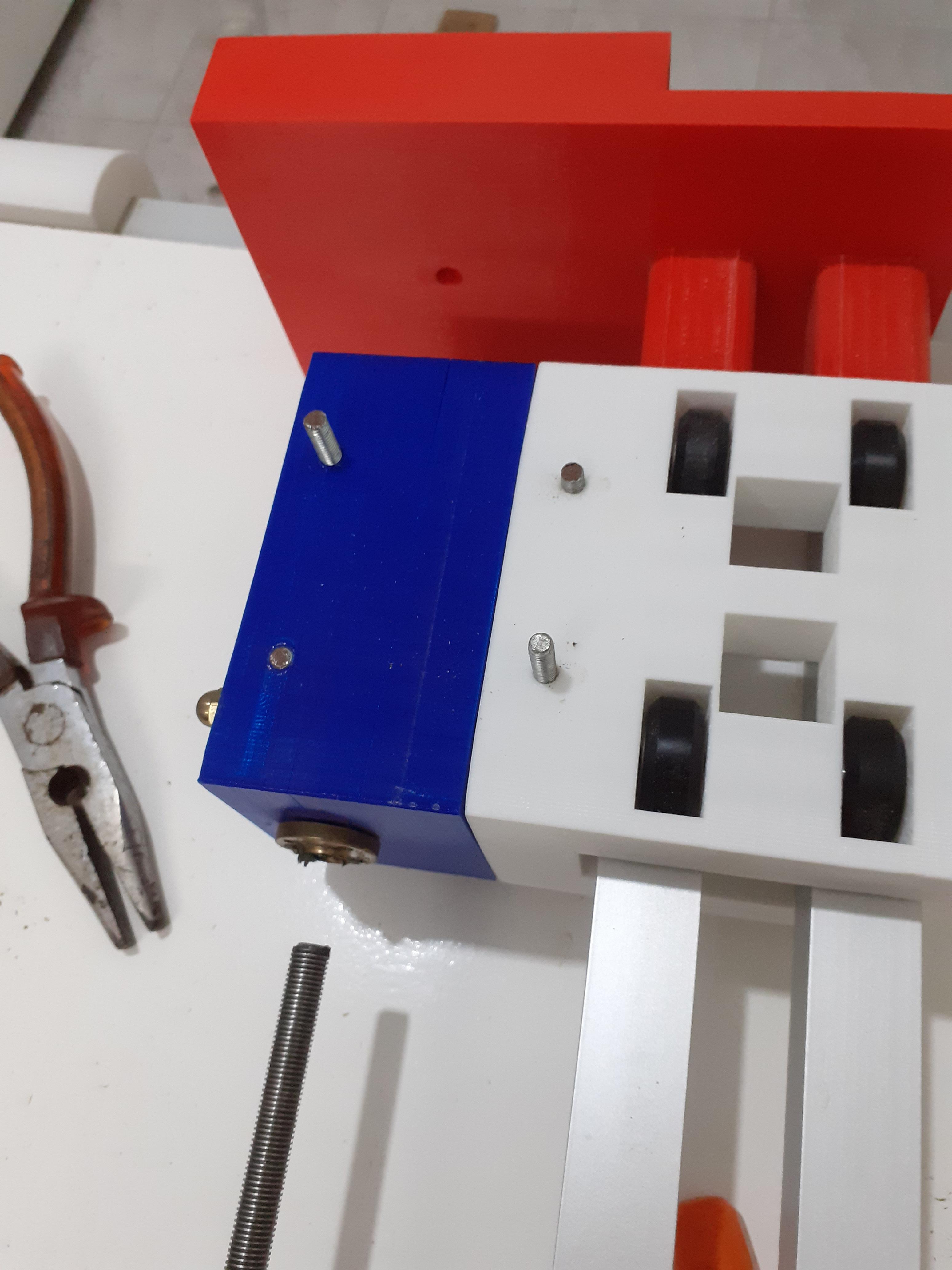
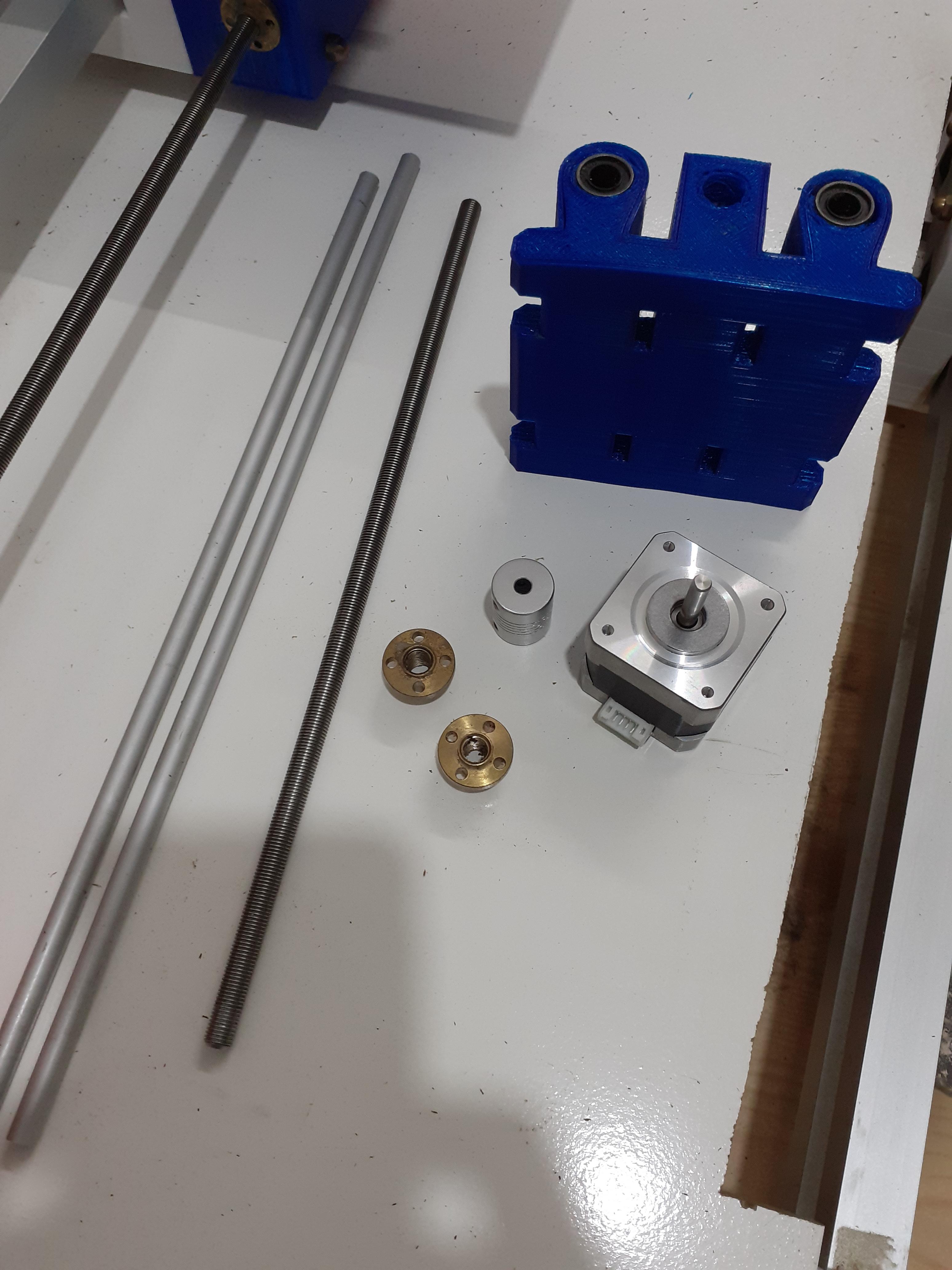
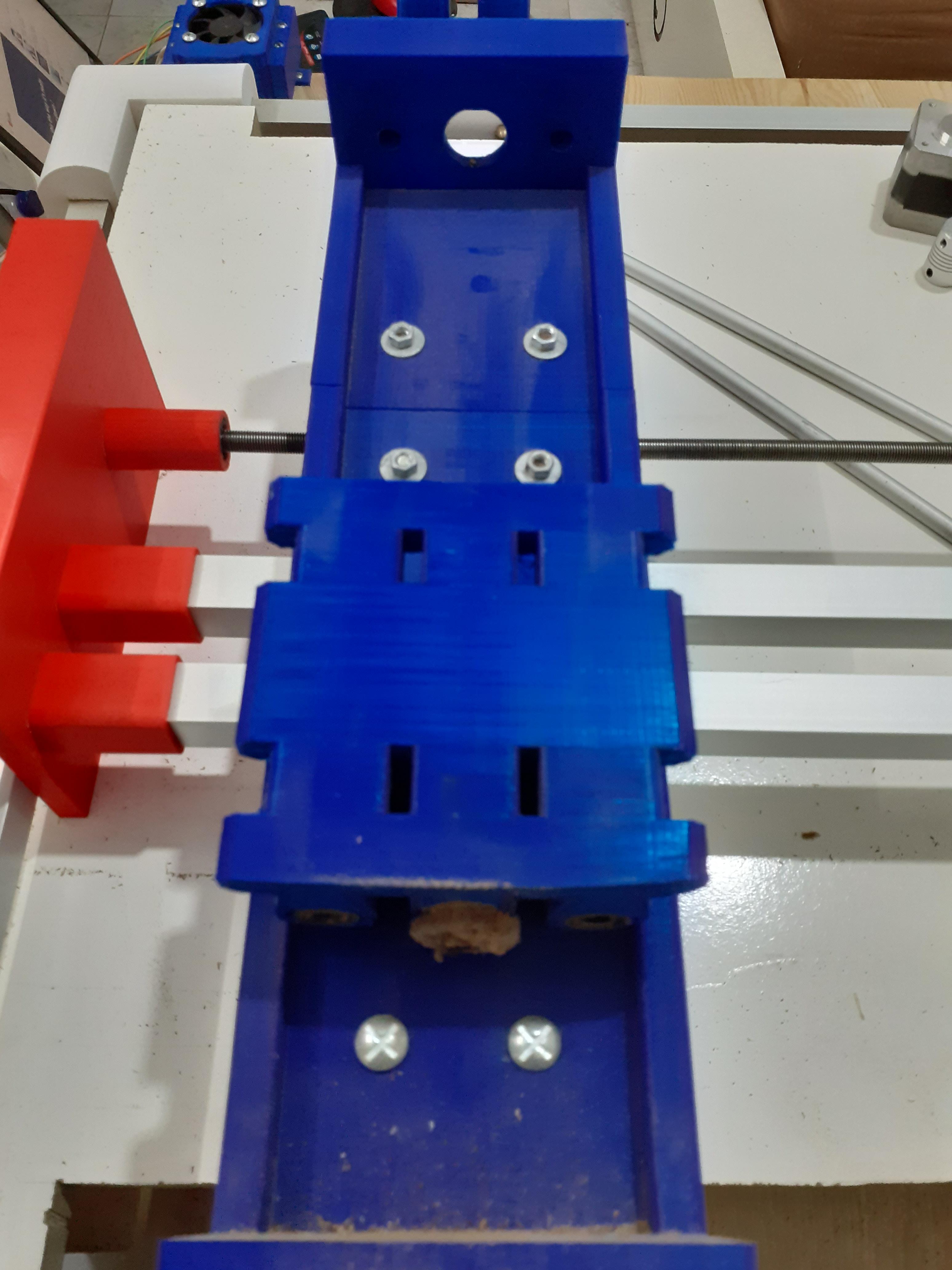
Mount the Top Slider for the Y-axis
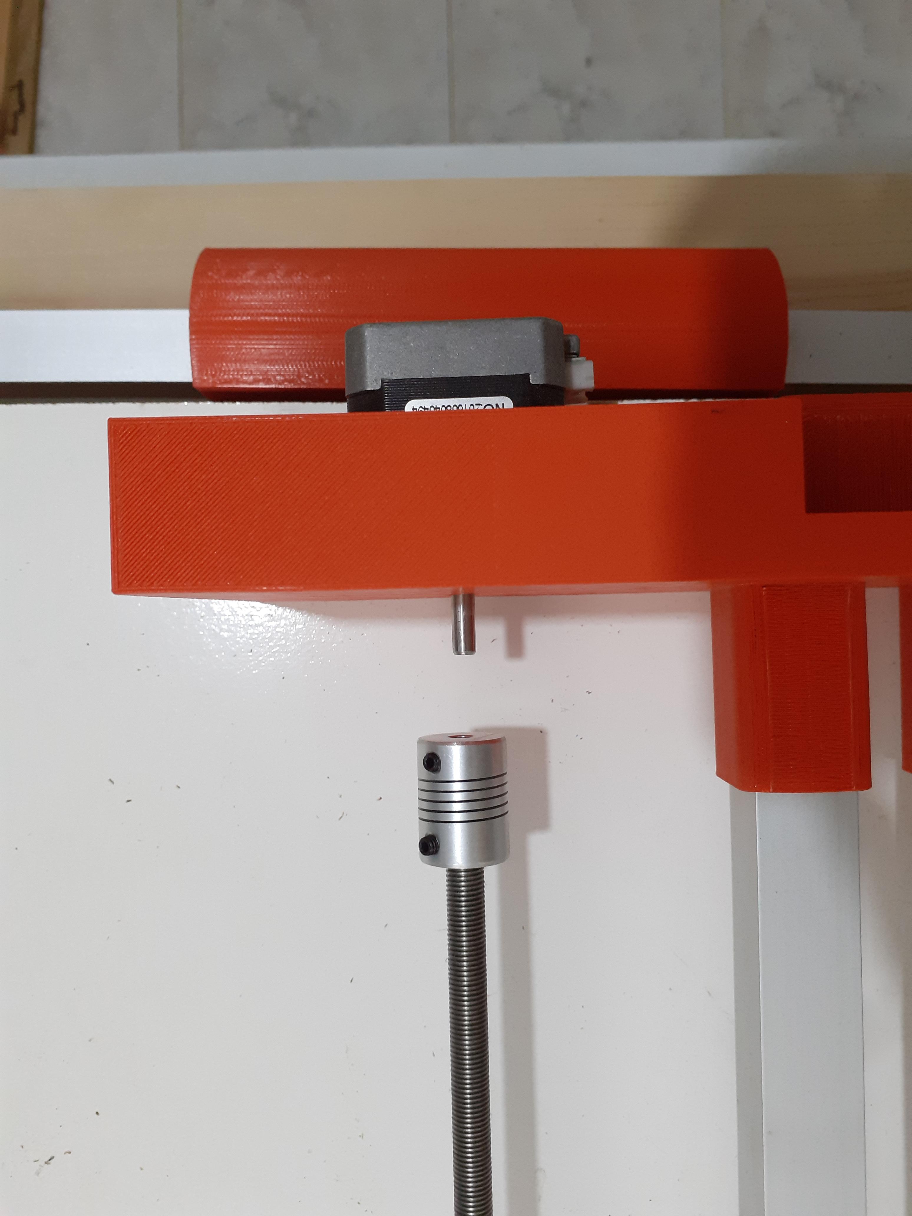
we're one step closer
- gather all the parts
- put the bearings into their places and attach them with the 5mm threaded rod
- add the top blue cover
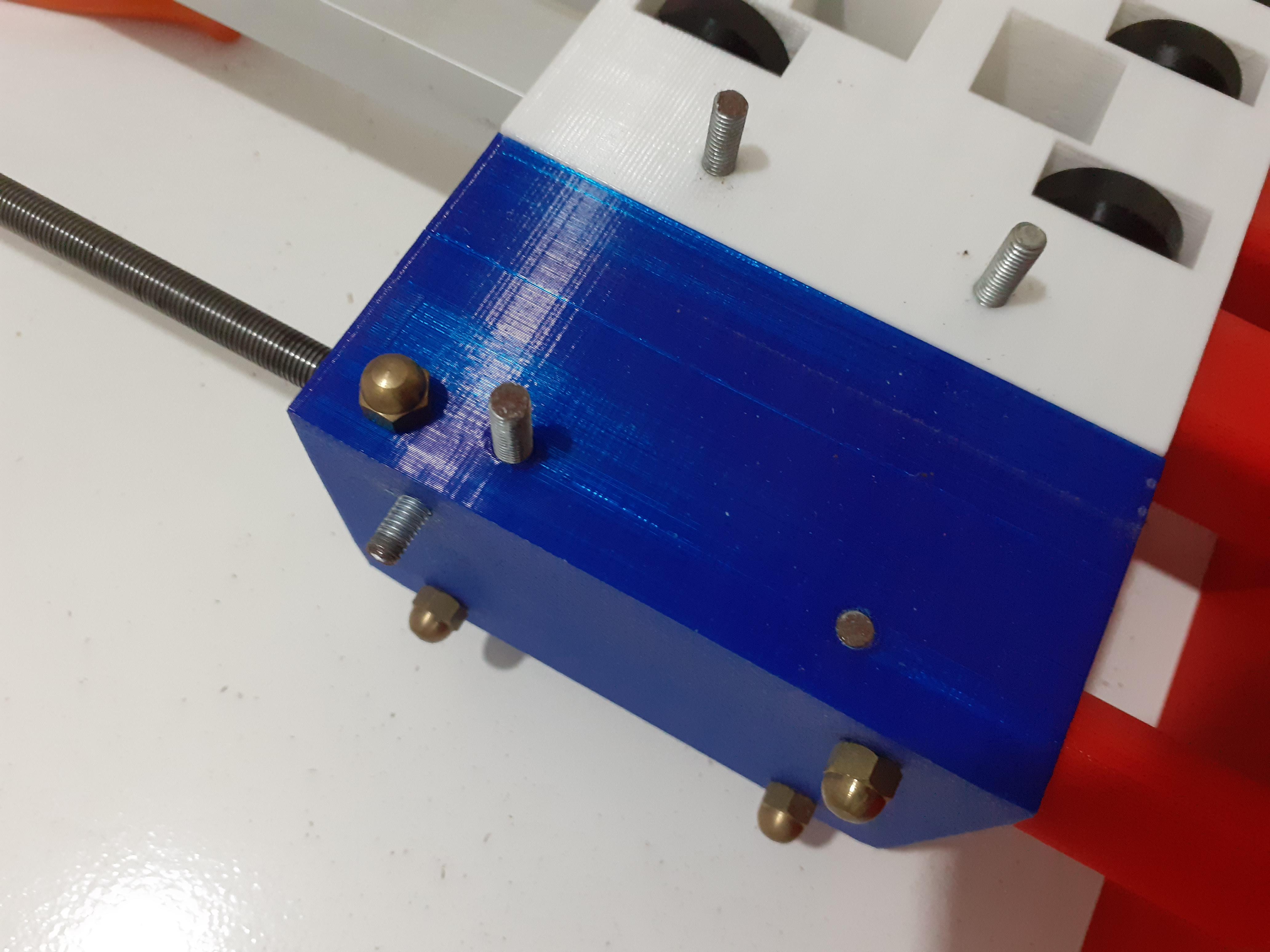
- add the side nuts for the leading screw
- insert the leading screw through the nuts
- put the motor into its place
- connect the leading screw and the motor with the help of a coupling
- finish the slider with the golden end cap nuts to cover the 5mm threaded rods
and that's your Y-axis is ready..... to the next step
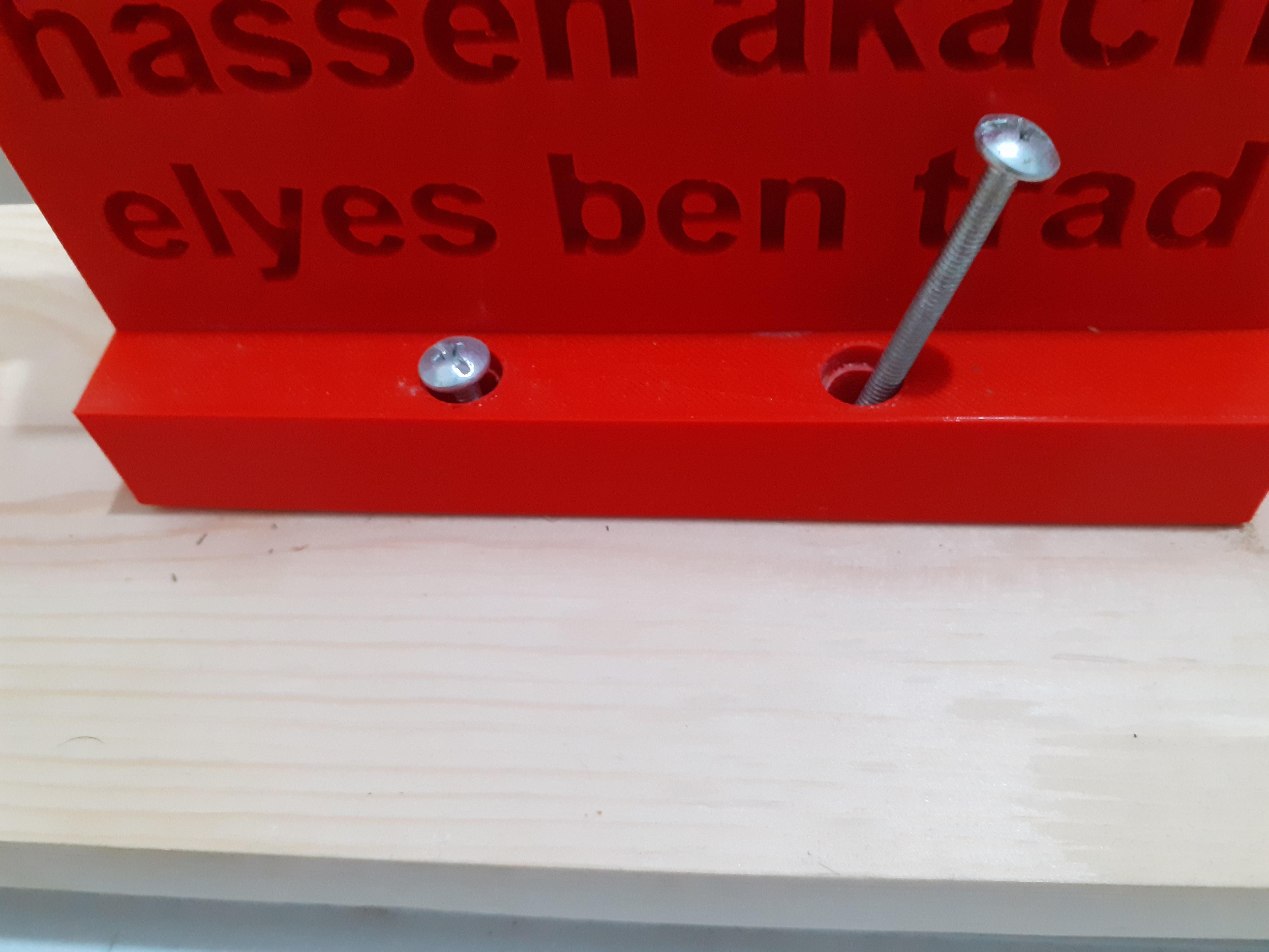
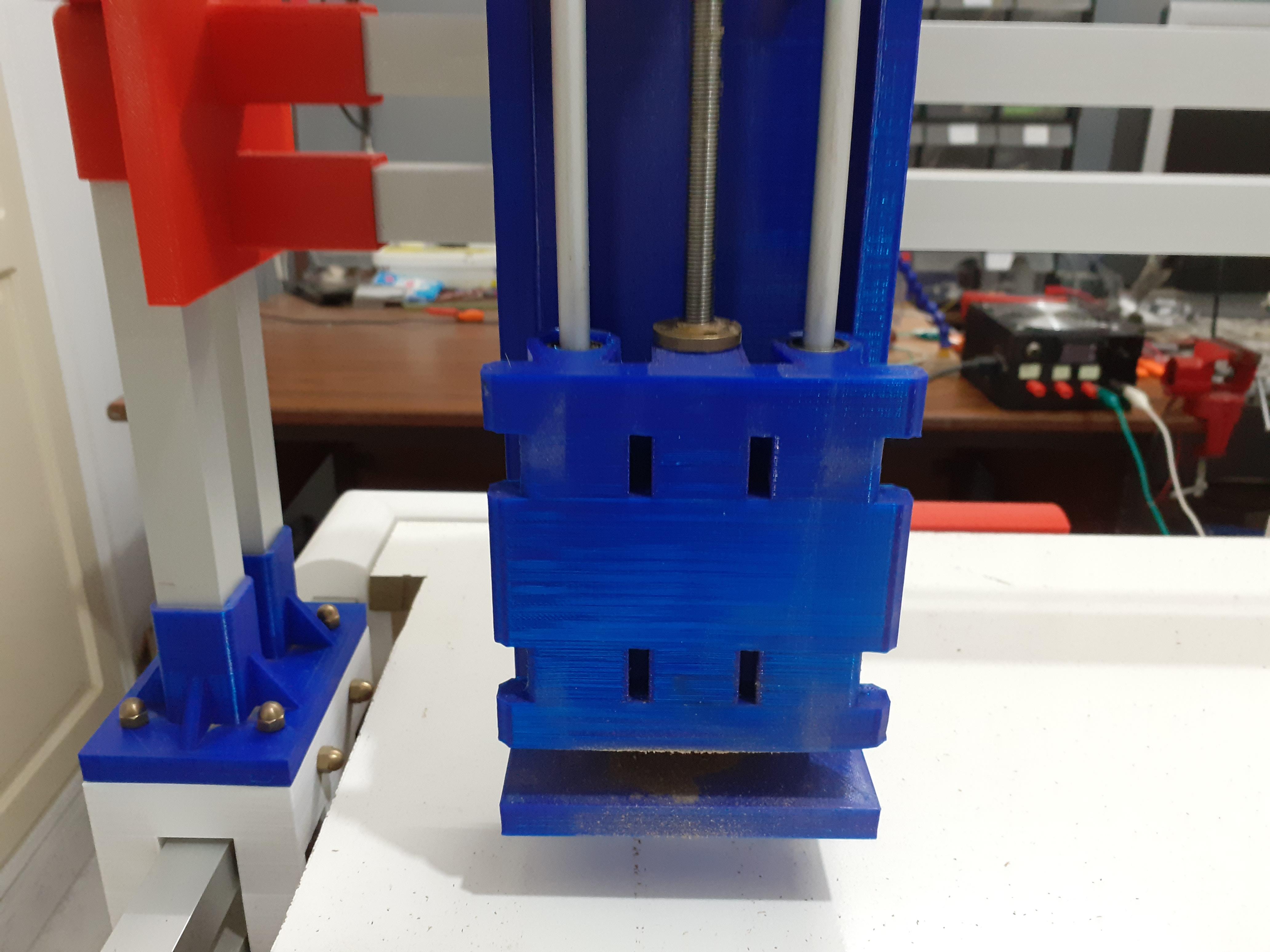
Mount the Base for the Z-axis
this the easiest one to mount
- gather the parts
- mount them as shown in the pictures
- and fix them with nuts
- that's it
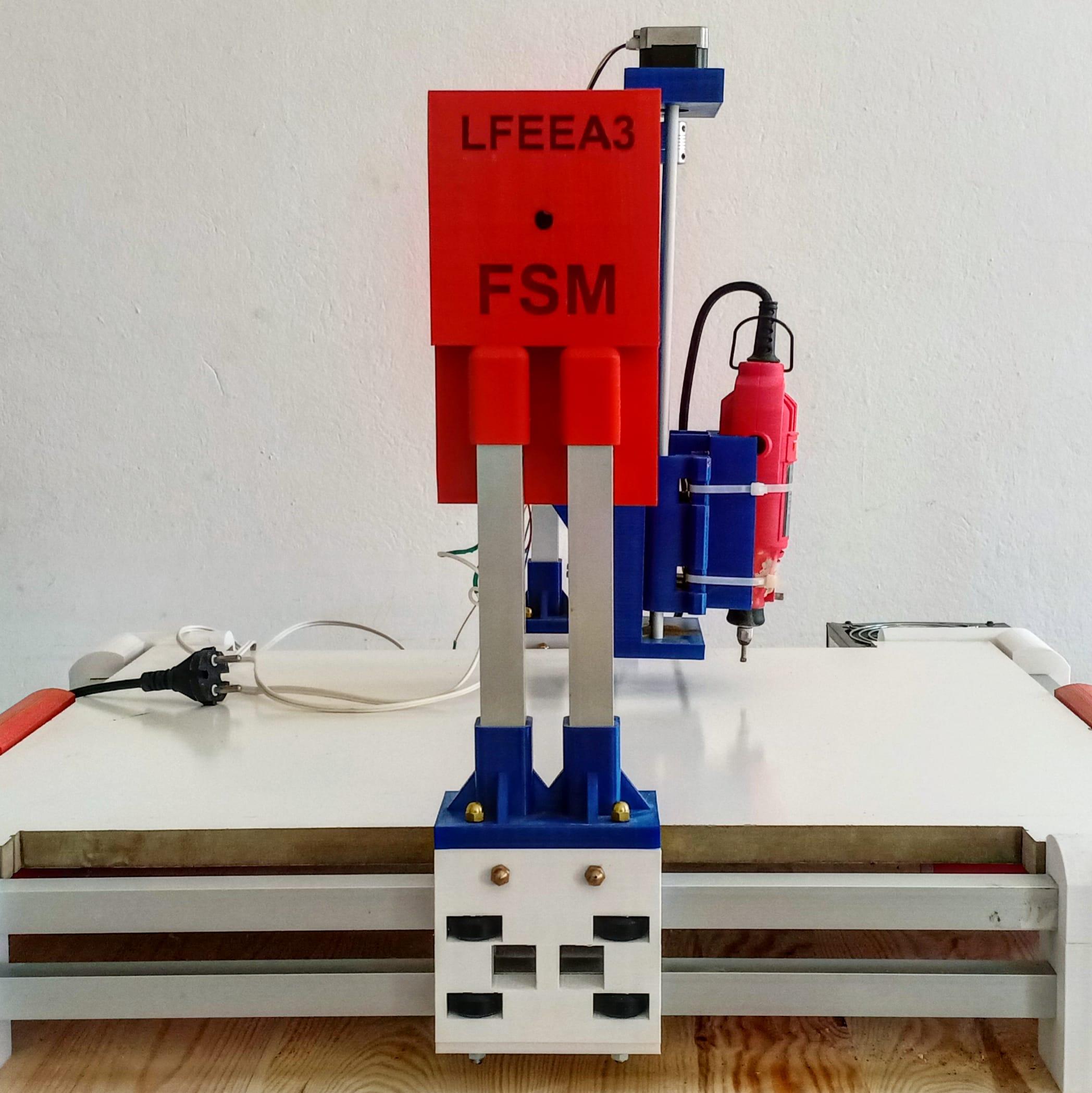
Mount the Z-axis
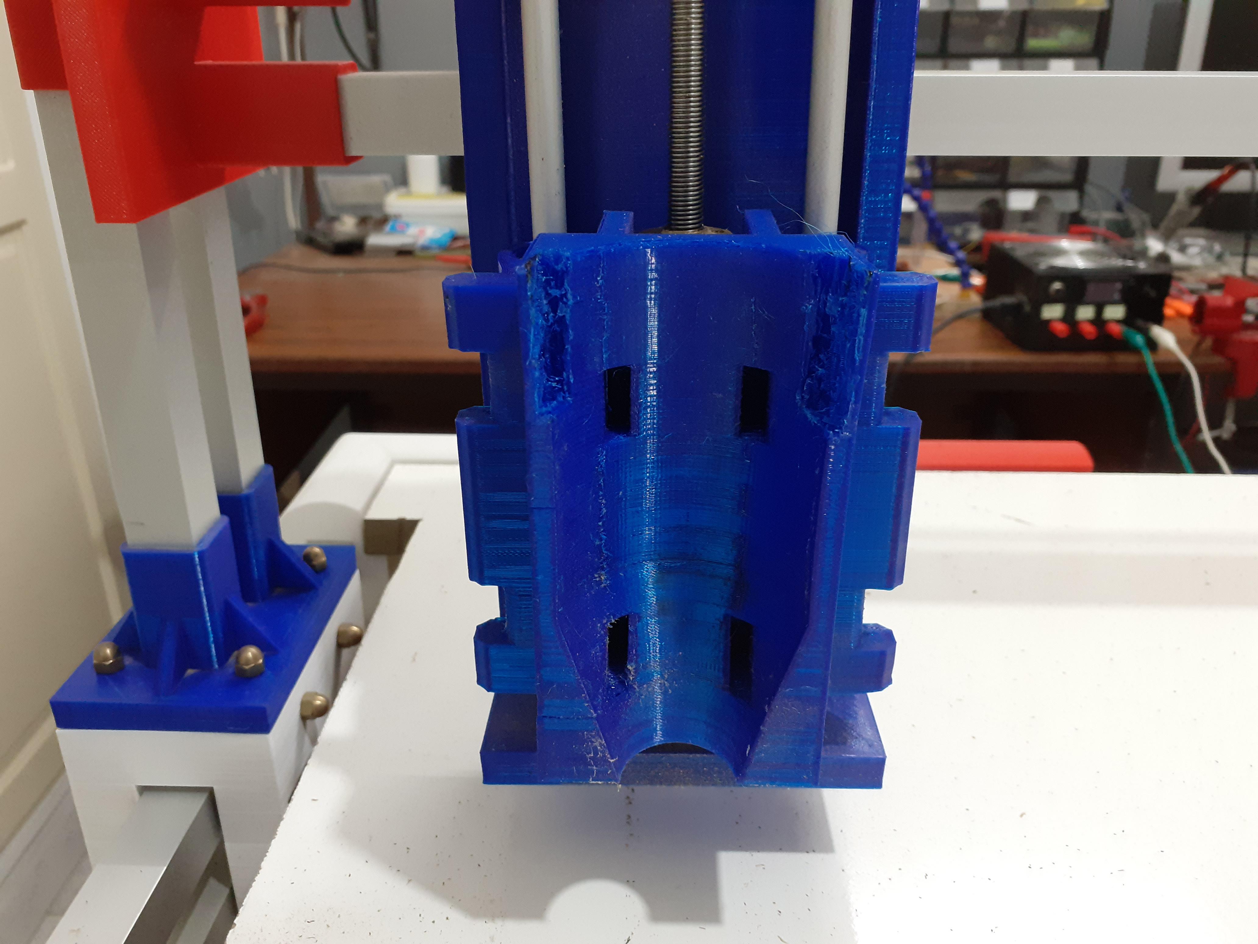
we're getting there
- gather the parts
- insert the two rods (so it can slide on)
- insert the two nuts
- insert the leading screw
- put the motor into it's place
- connect the leading screw with motor with the help of a coupling
- add the drill adapter (very easy to mount just slide it in ....check design)
- follow the pictures to make sure you did everything right
only one step more for the mechanical build
Attach the Drill
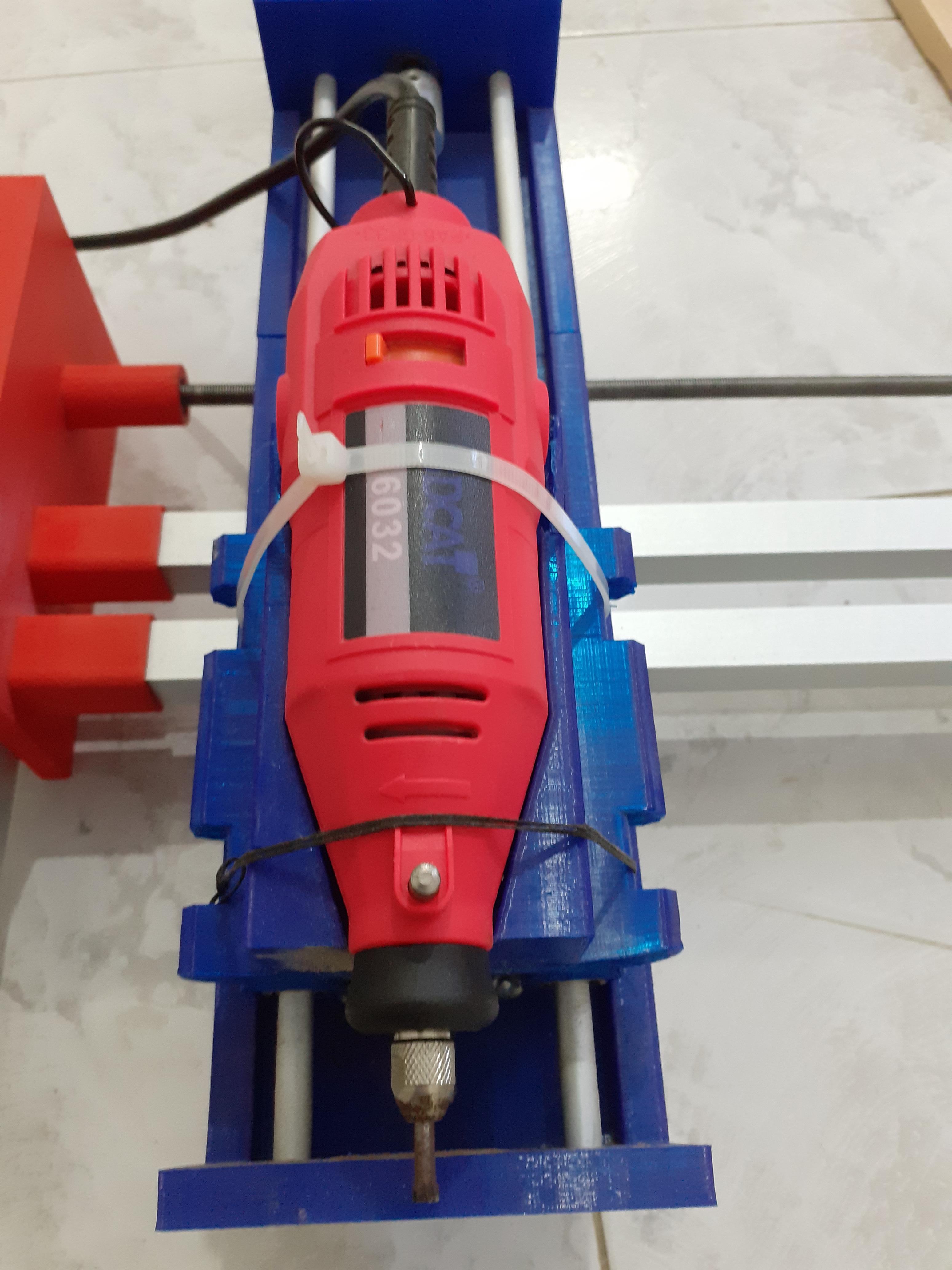
this super easy just put the drill and hold it with zip ties or with a thread
I personally prefer the zip ties ...easier to use
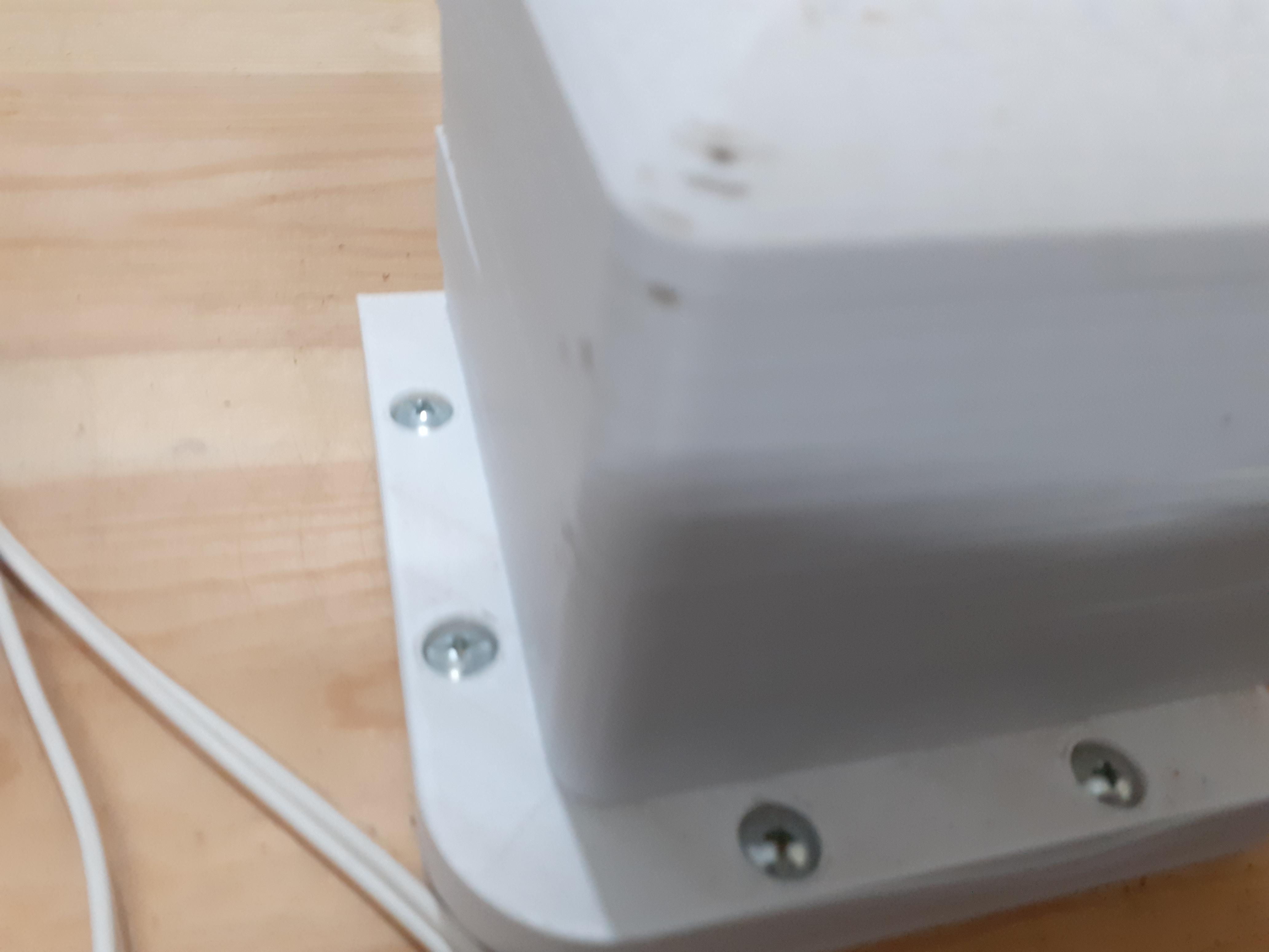
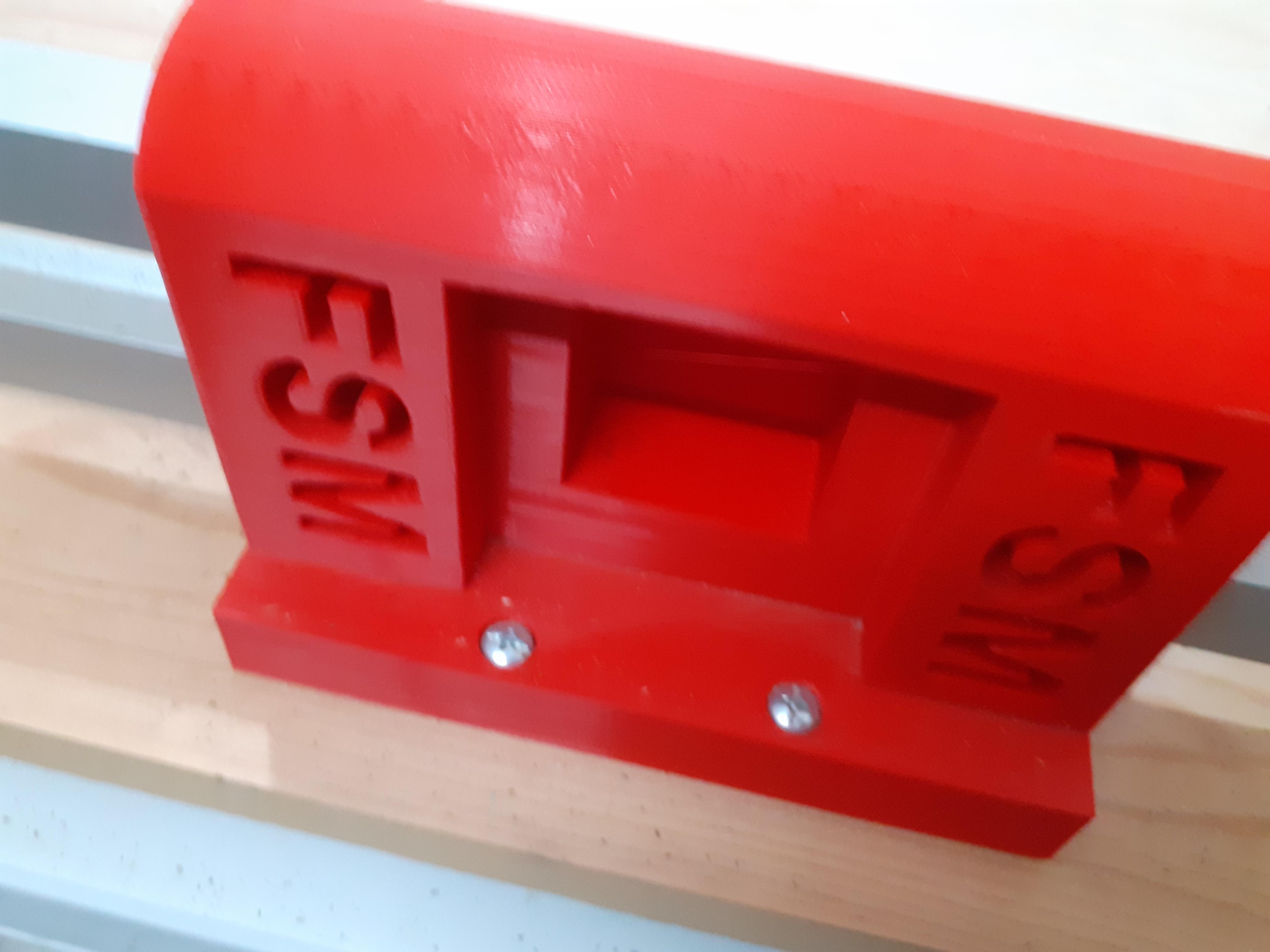
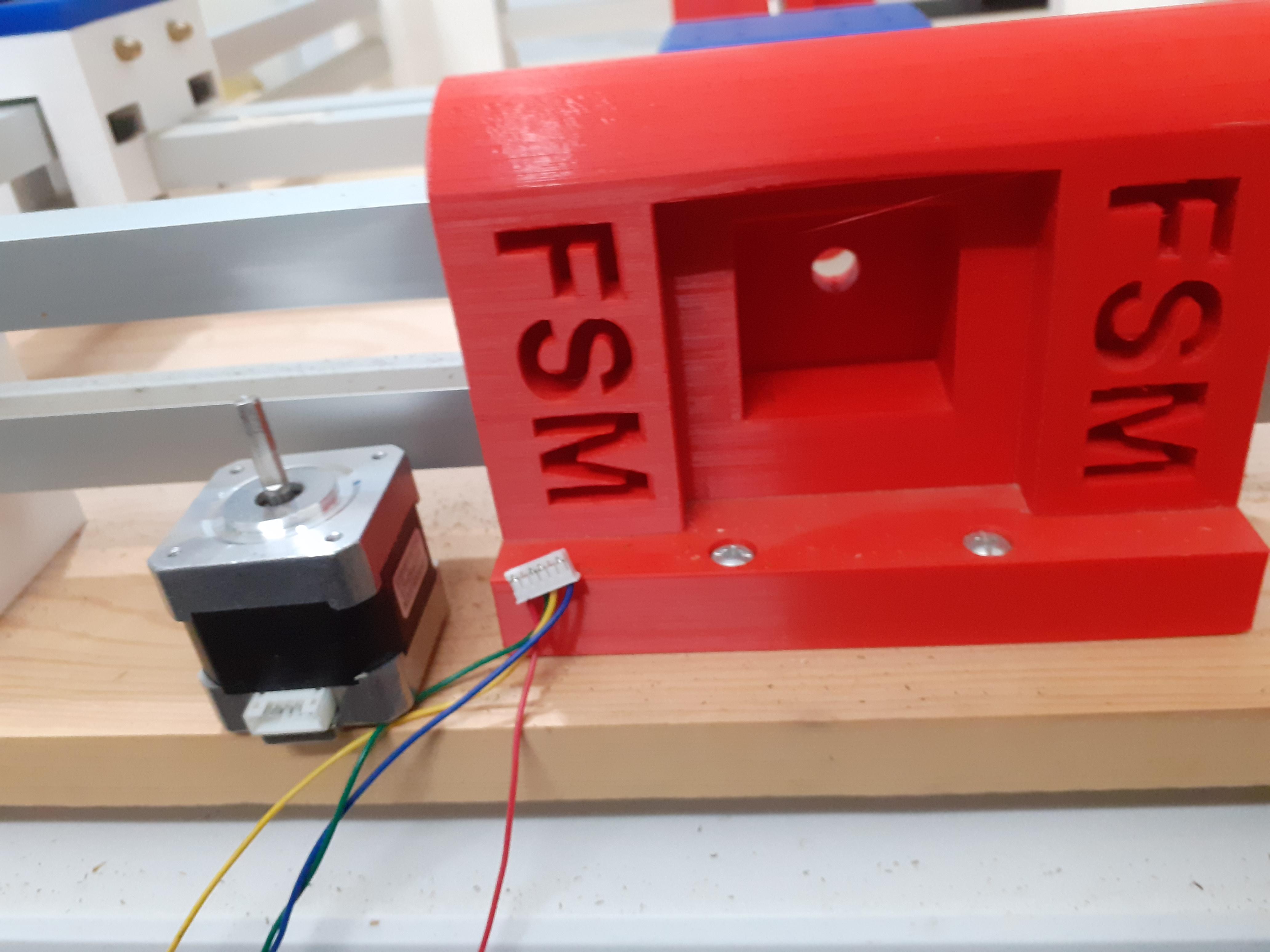
Electronic Housing
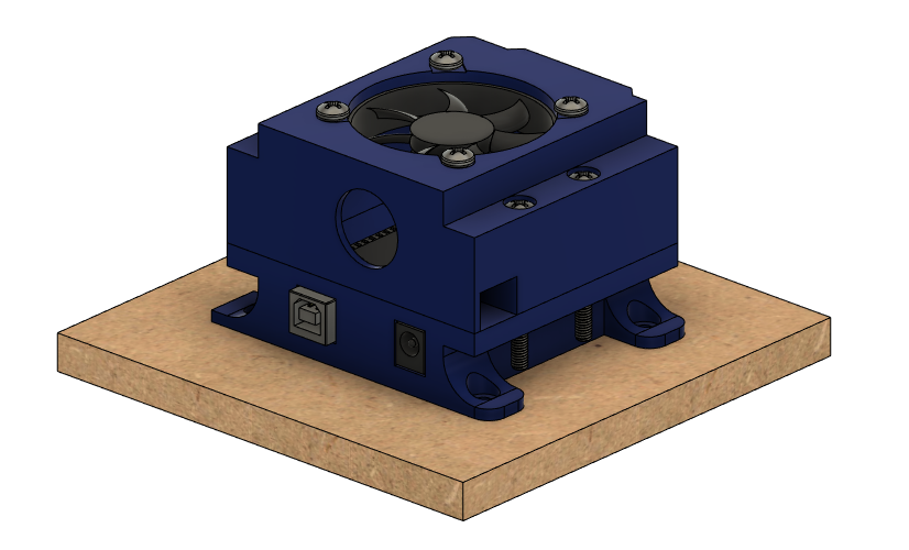
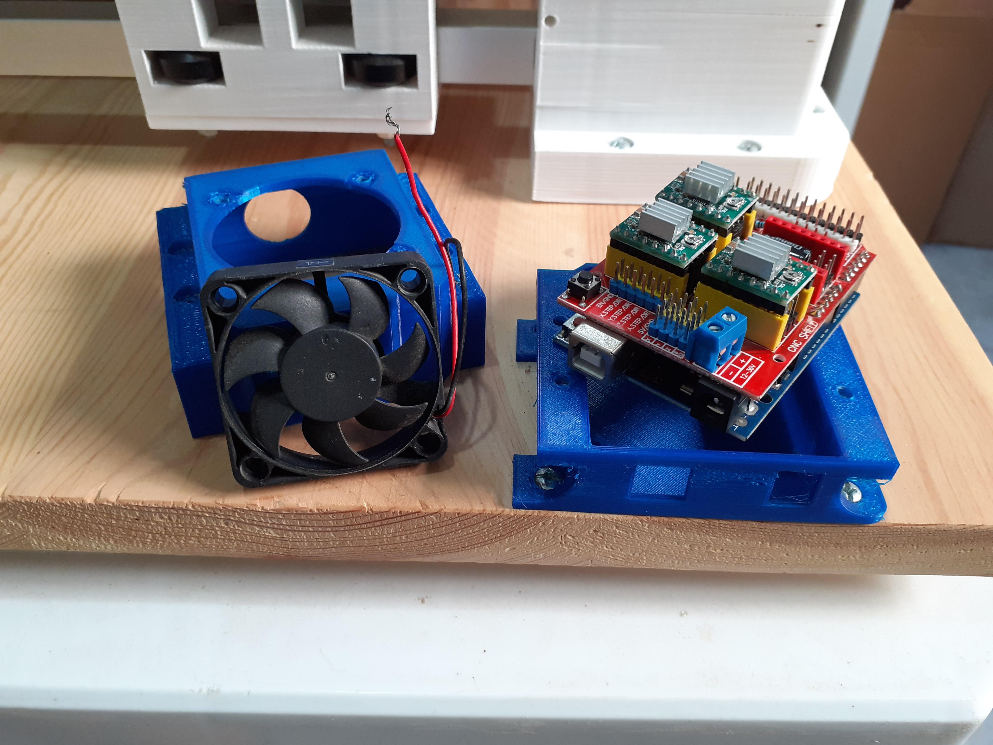
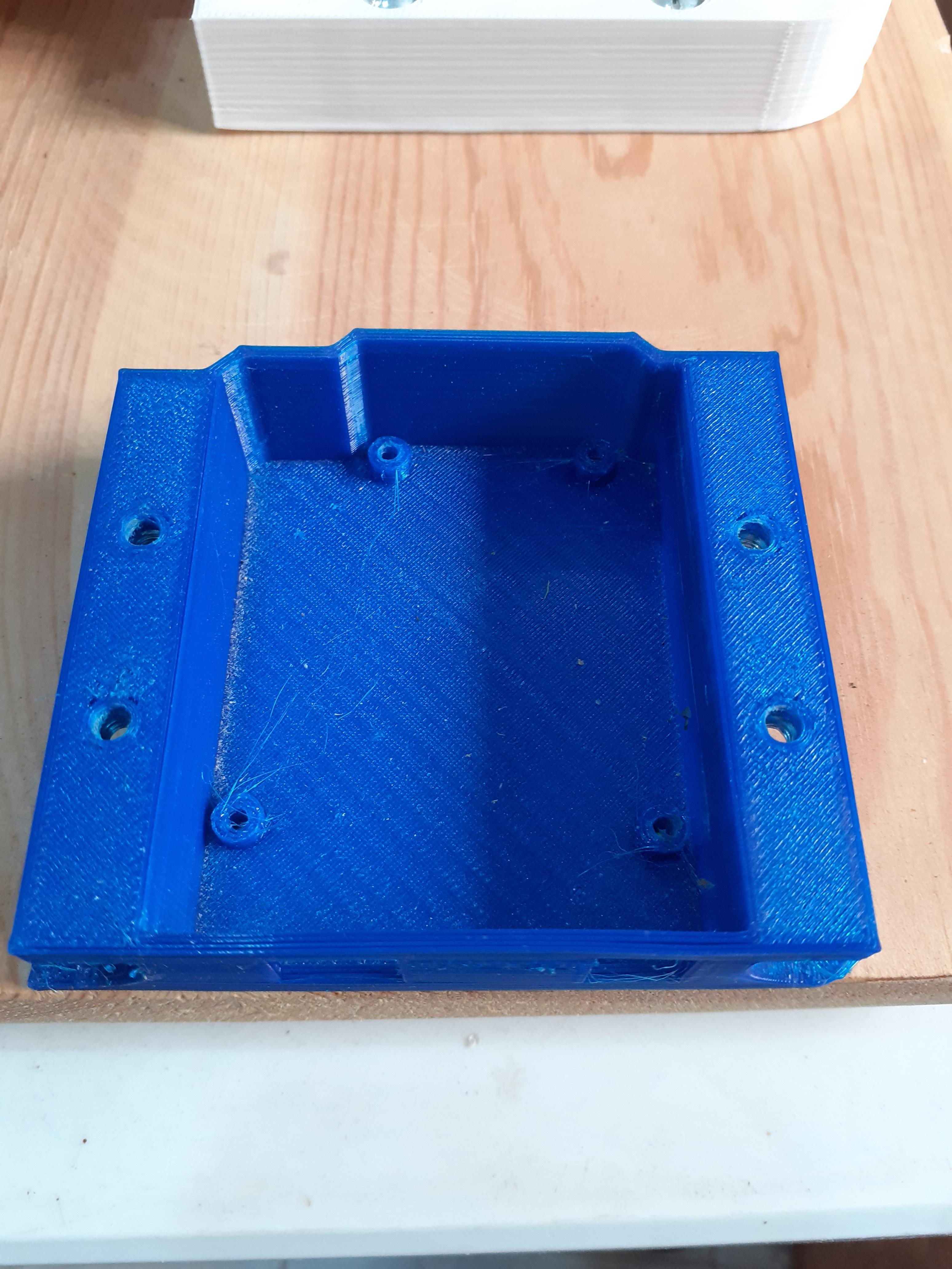
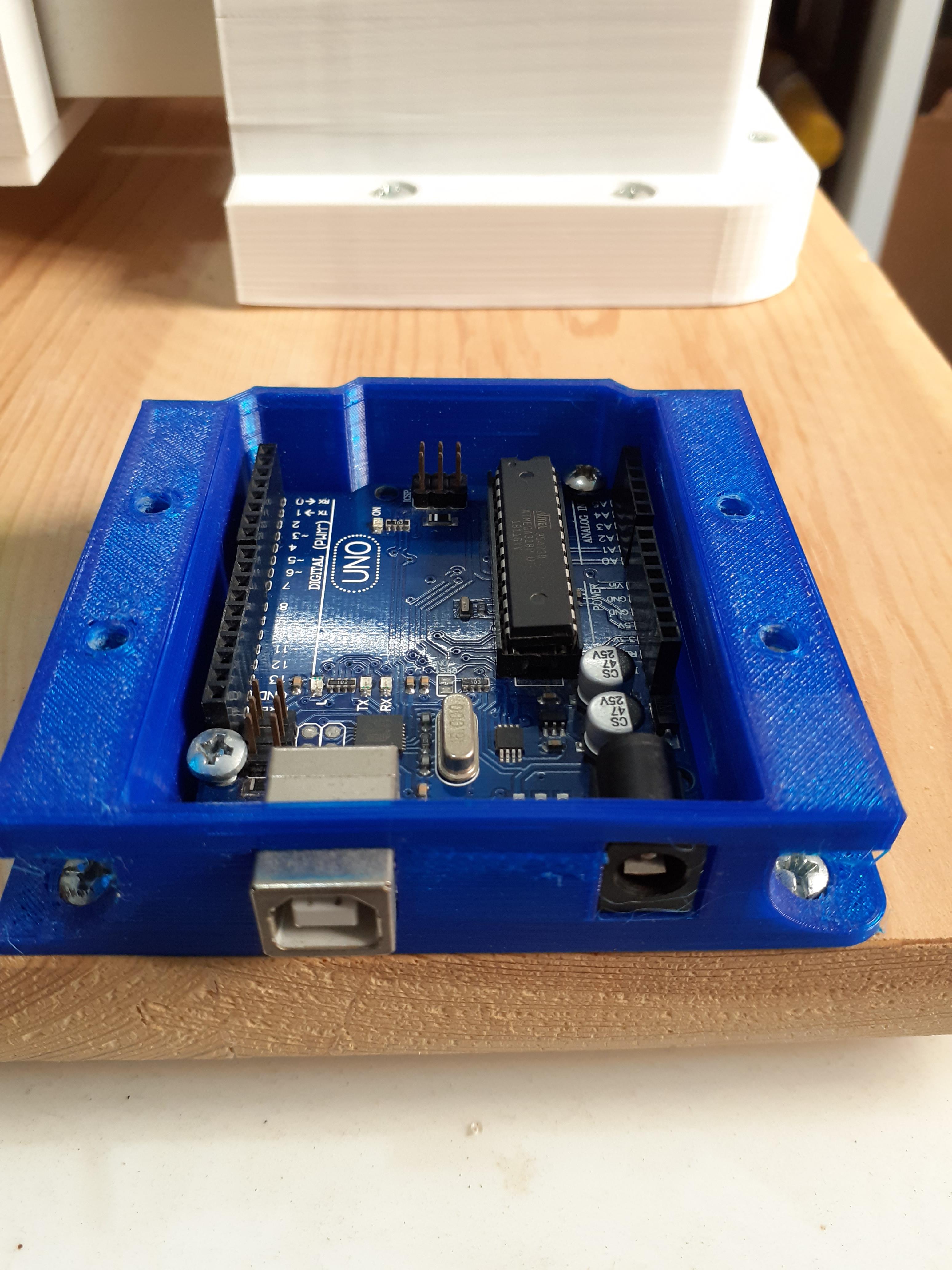
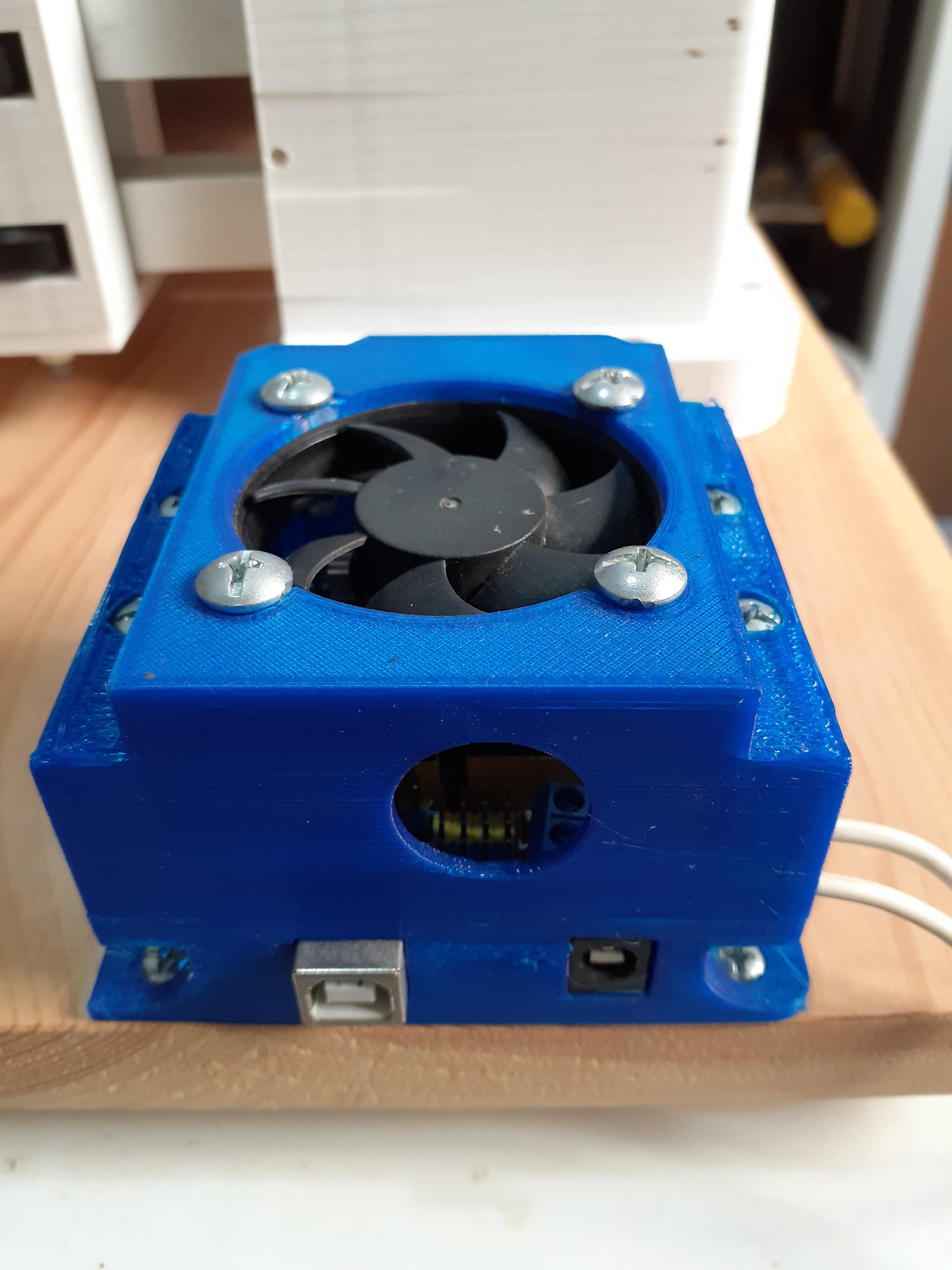
for the electronics part
- print the housing
- get your parts
- attach the housing base to the wood board
- insert the Arduino inside and hold it with screws
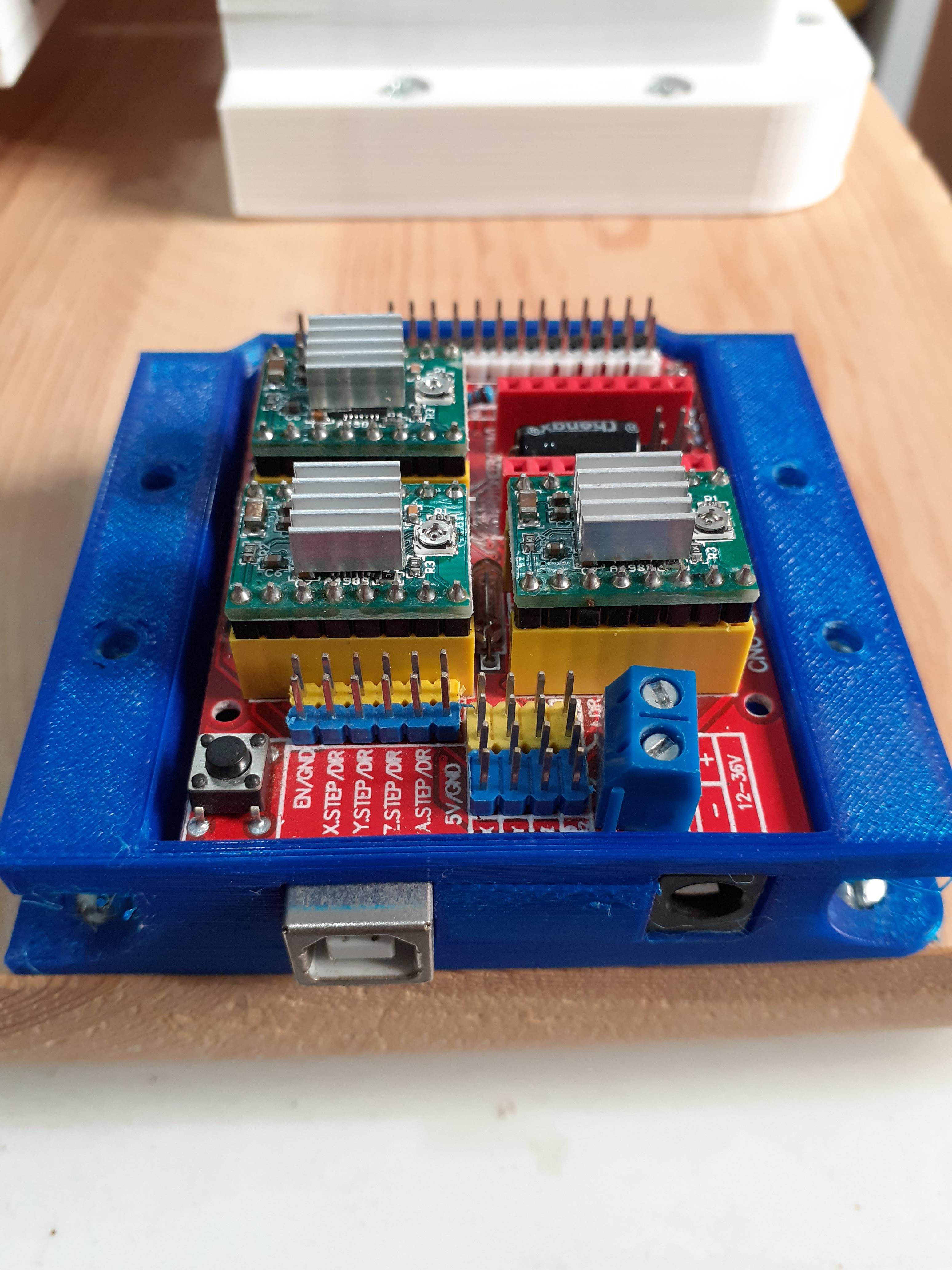
- mount the shield on the Arduino
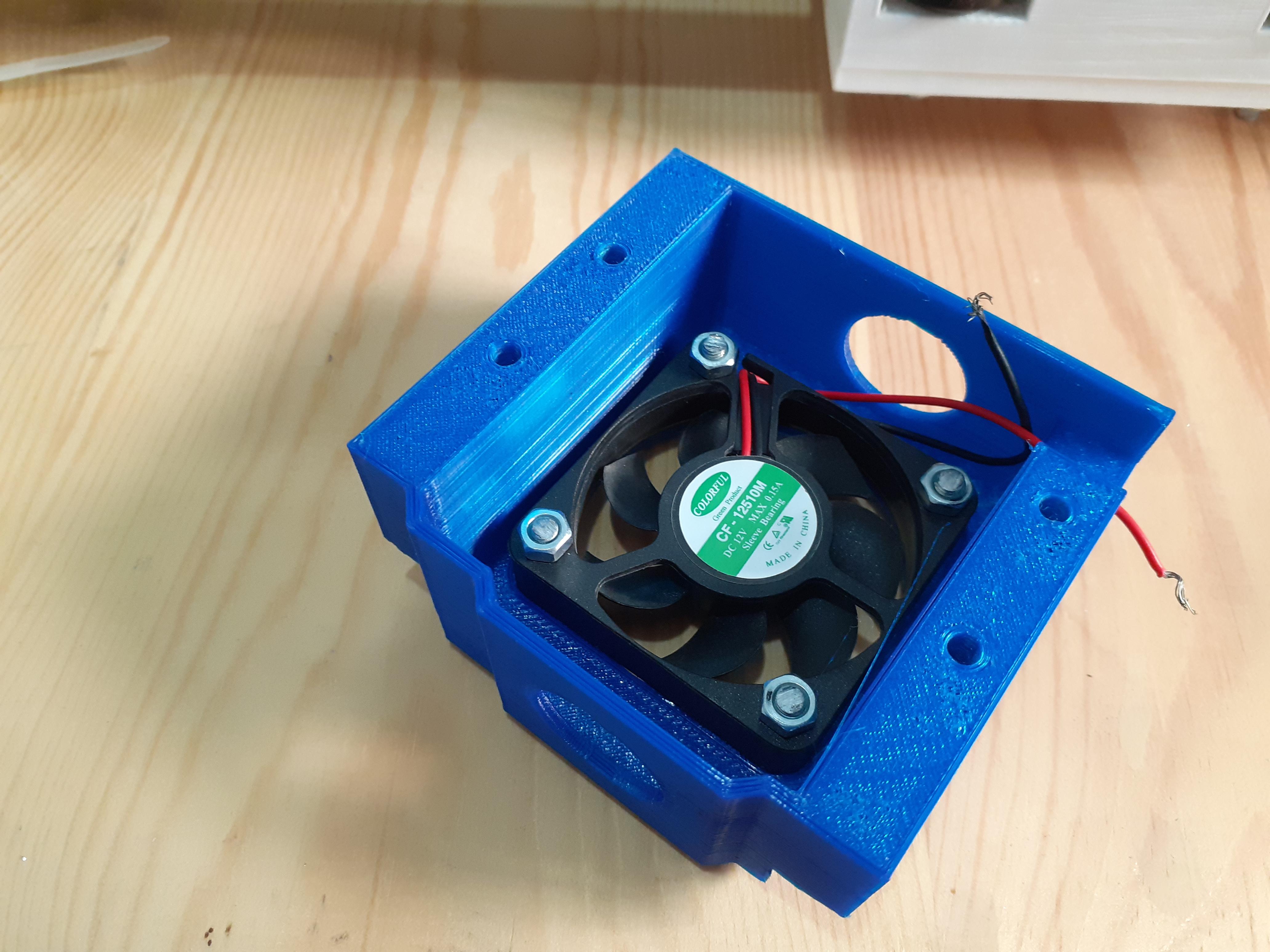
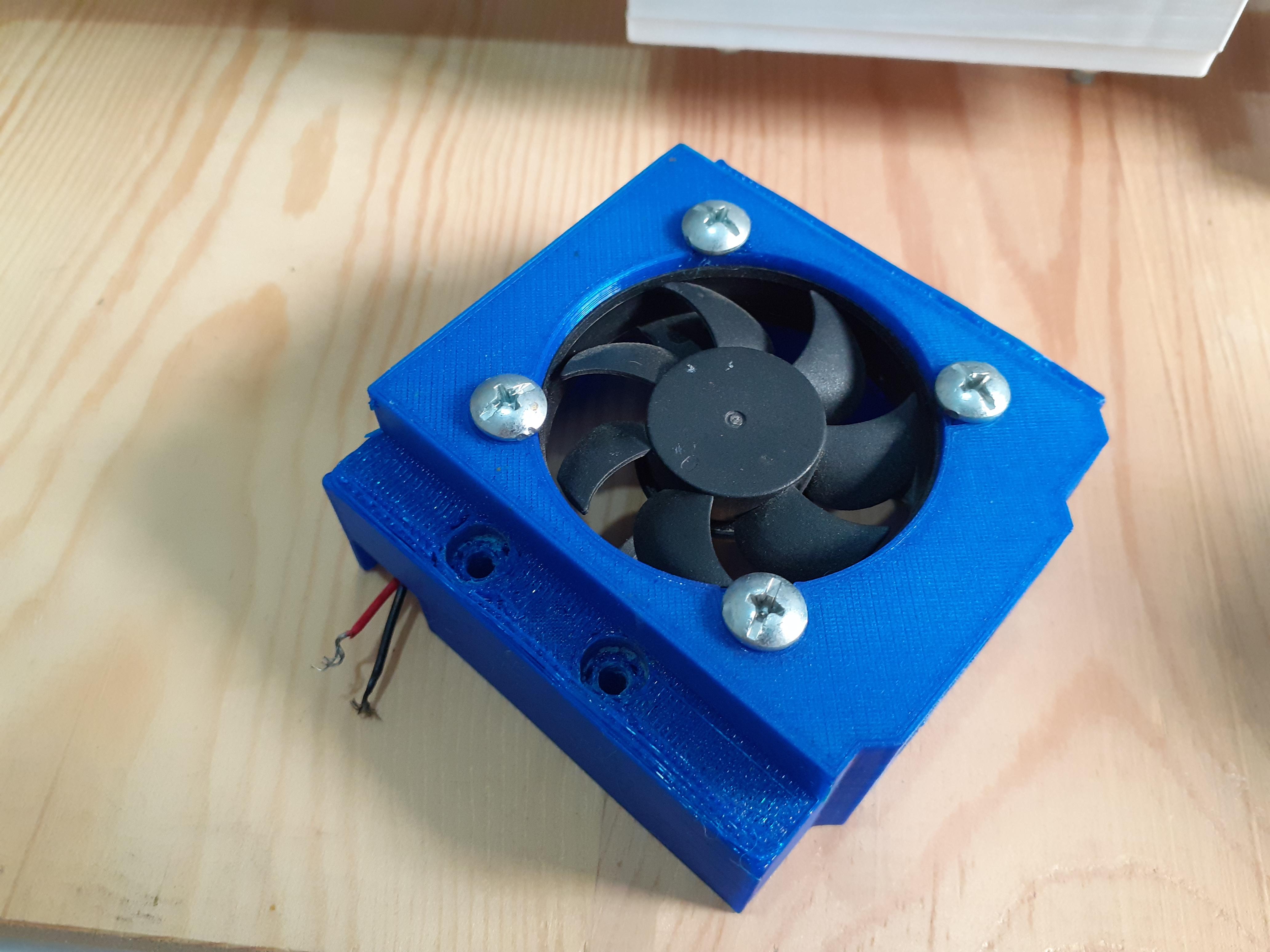
- mount the fan in the right direction in the top part of the housing
- connect the two parts together
that's it for electronics ...you're almost there
Mount Cables
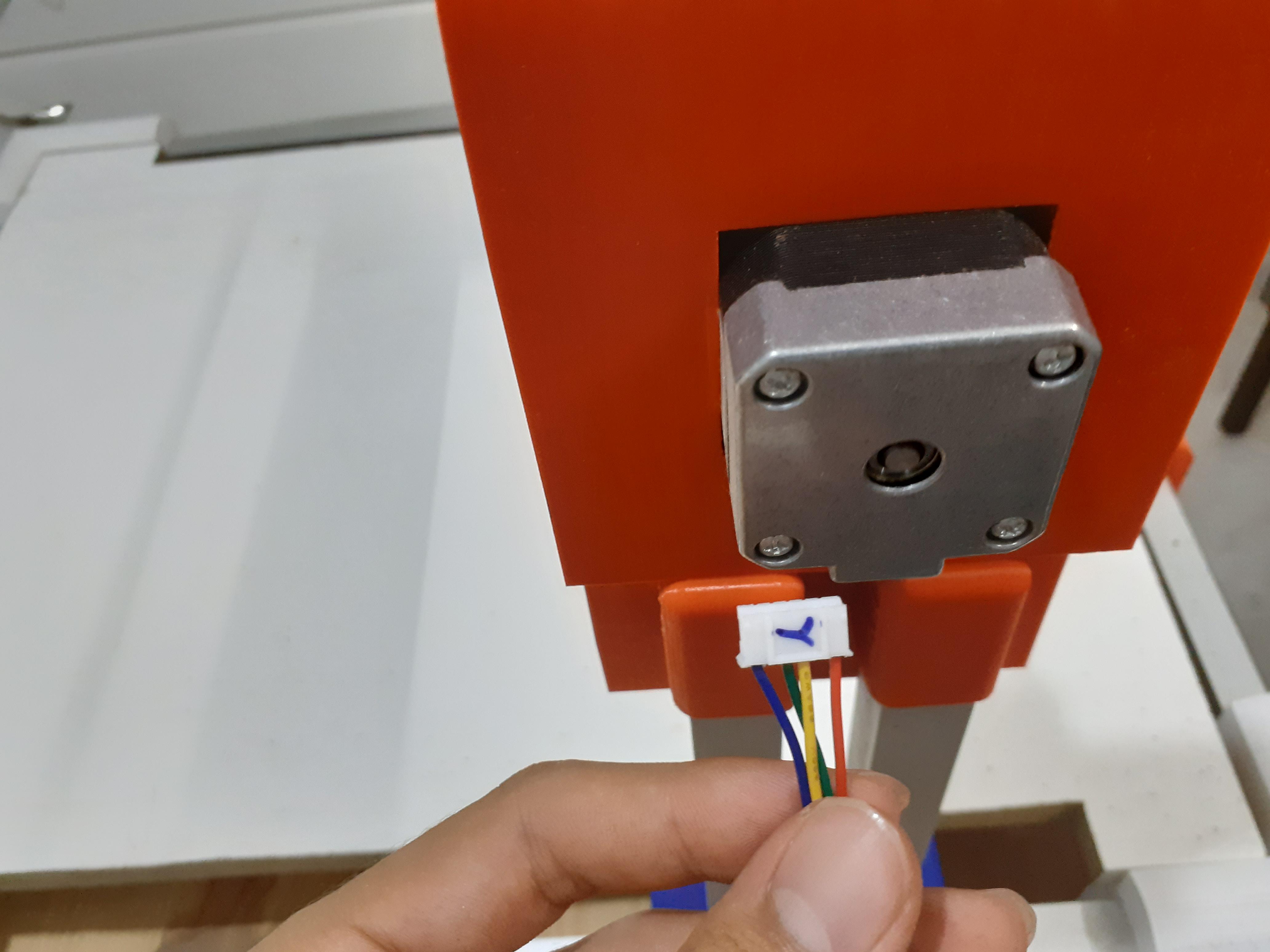
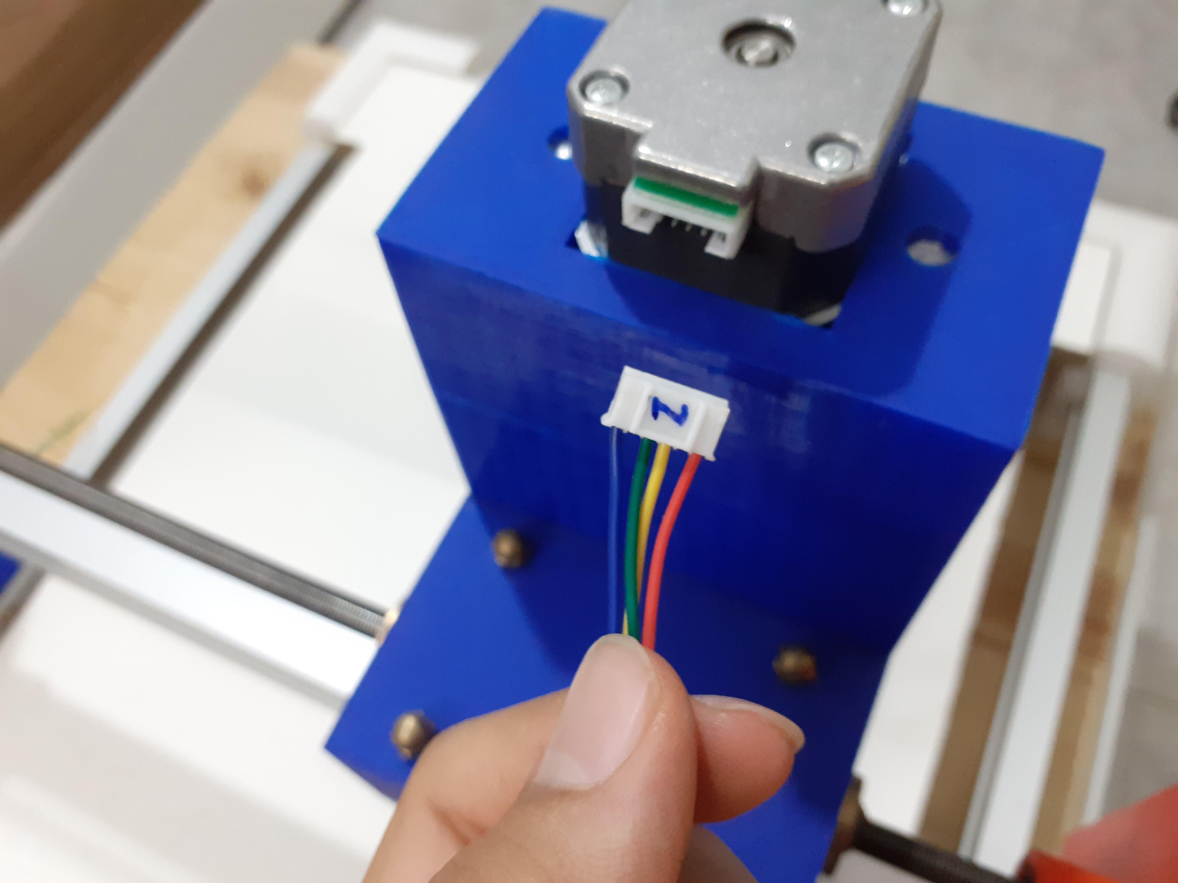
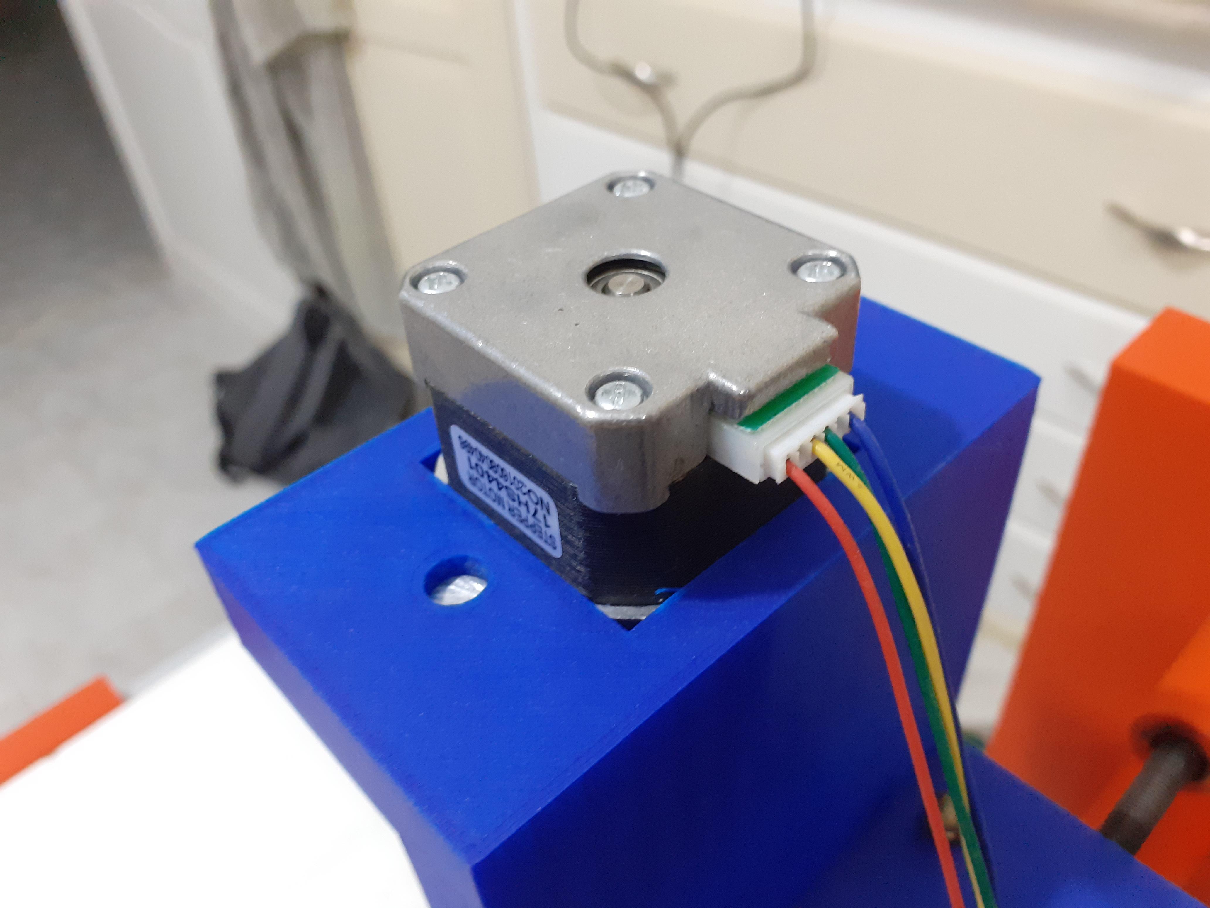
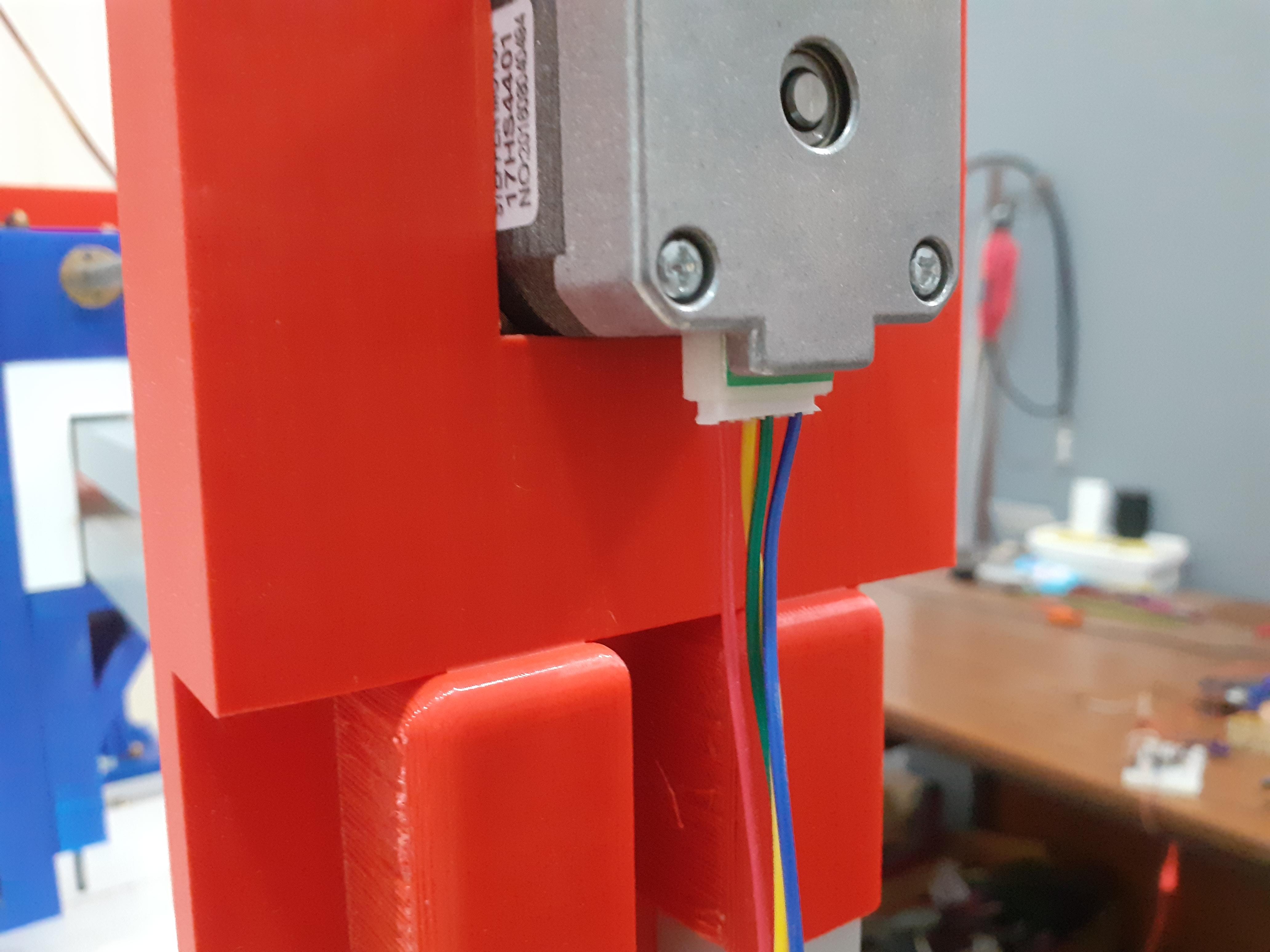
don't worry there is no complex schematics to follow it's very simple everything is written on the shield just connect the motor with its right port and you are wired haha
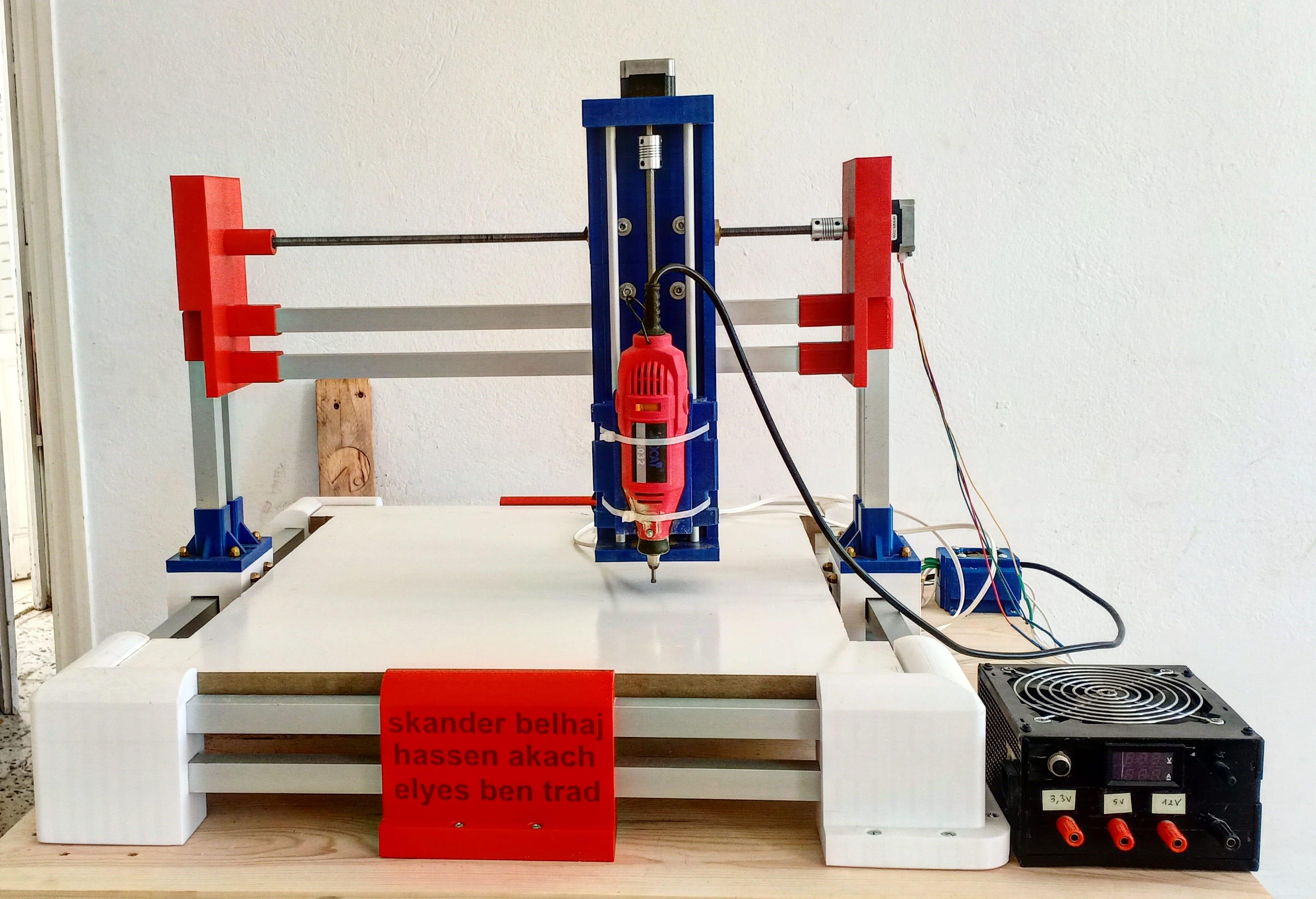
Power Supply

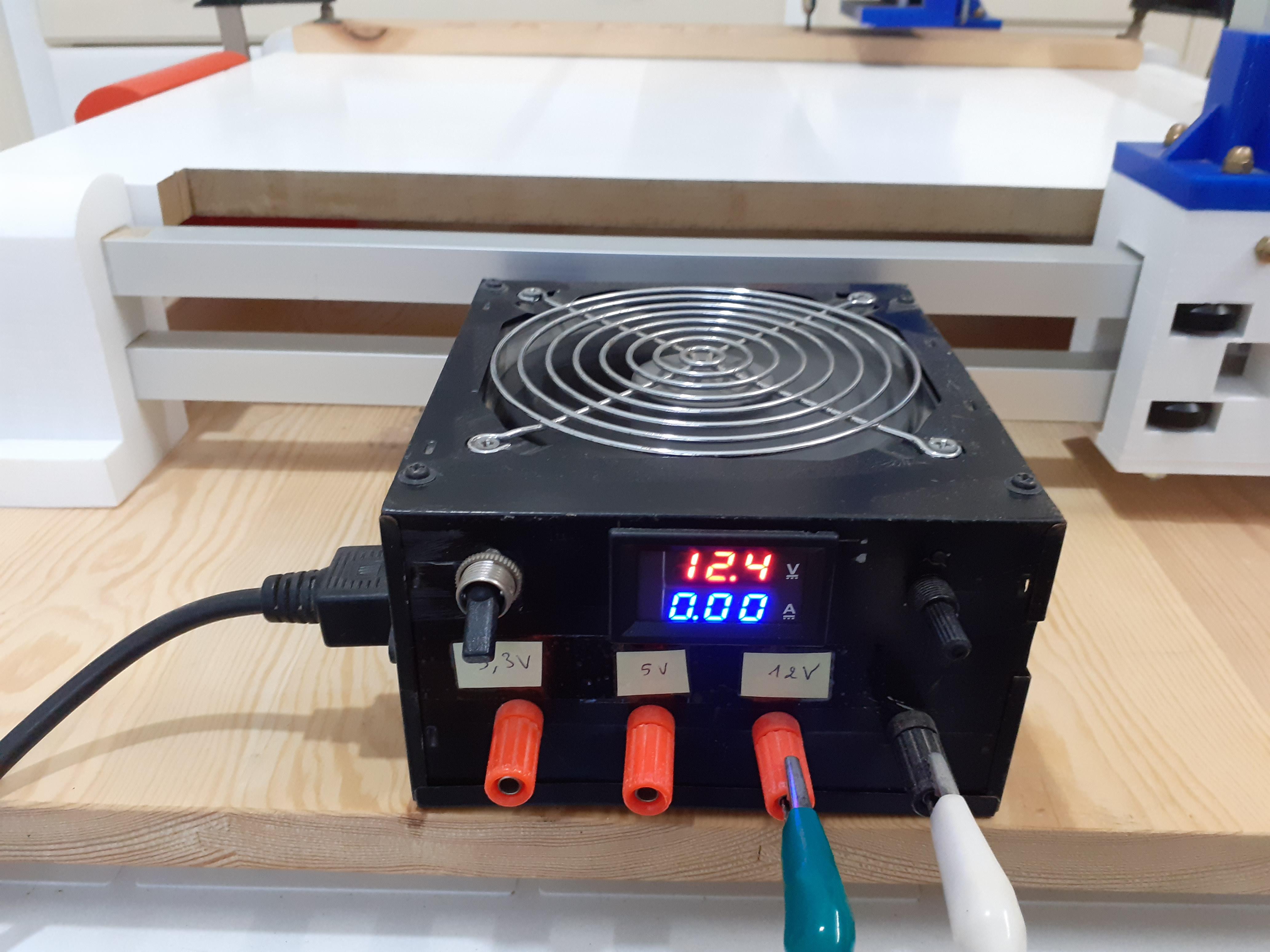
I made my own power supply but you don't have to you can just buy it or borrow it haha
Software Part
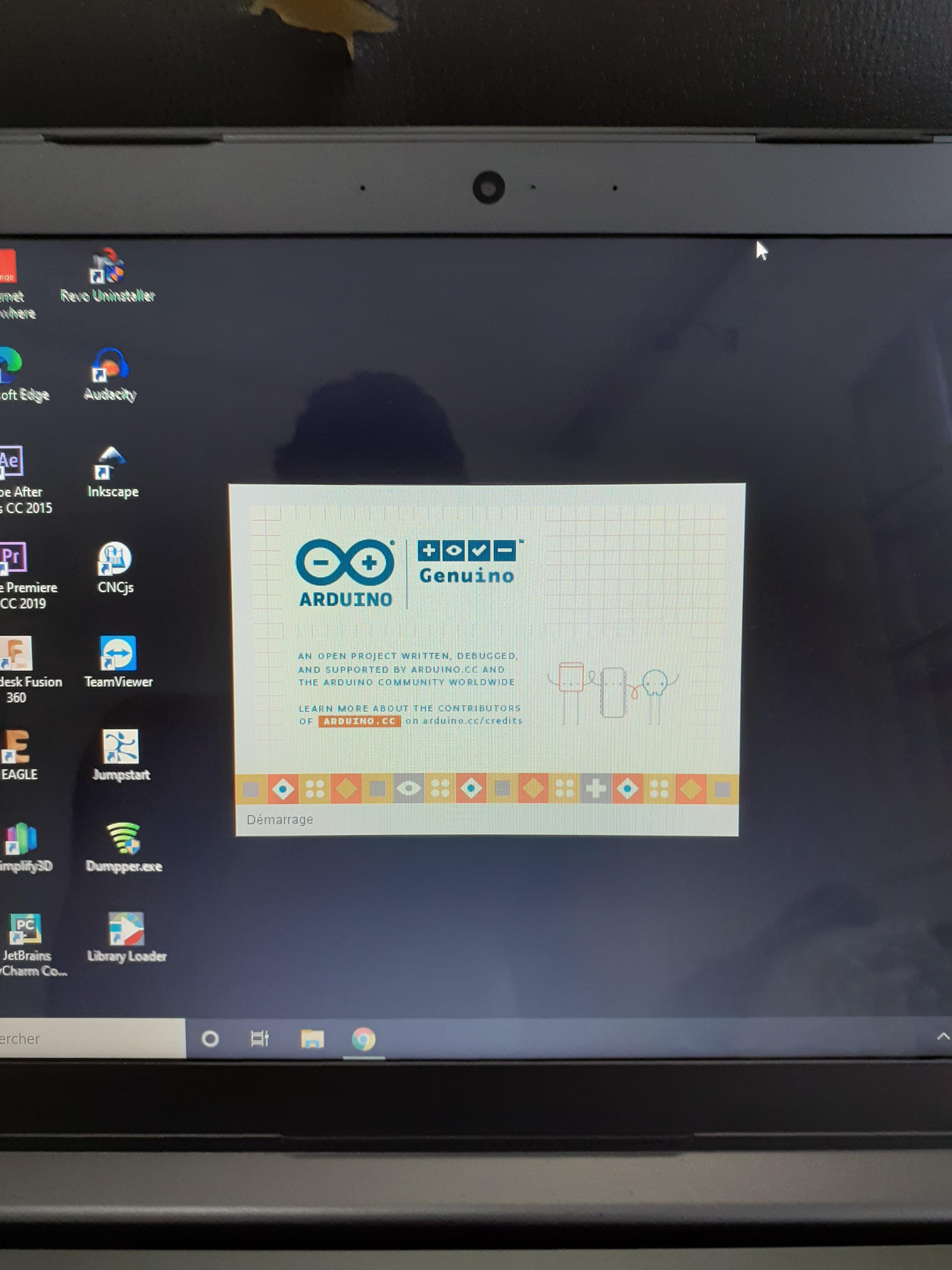
the software part is also easy to do
- upload the Arduino IDE
- upload the grbl firmware to arduino (you can find it online just google it)
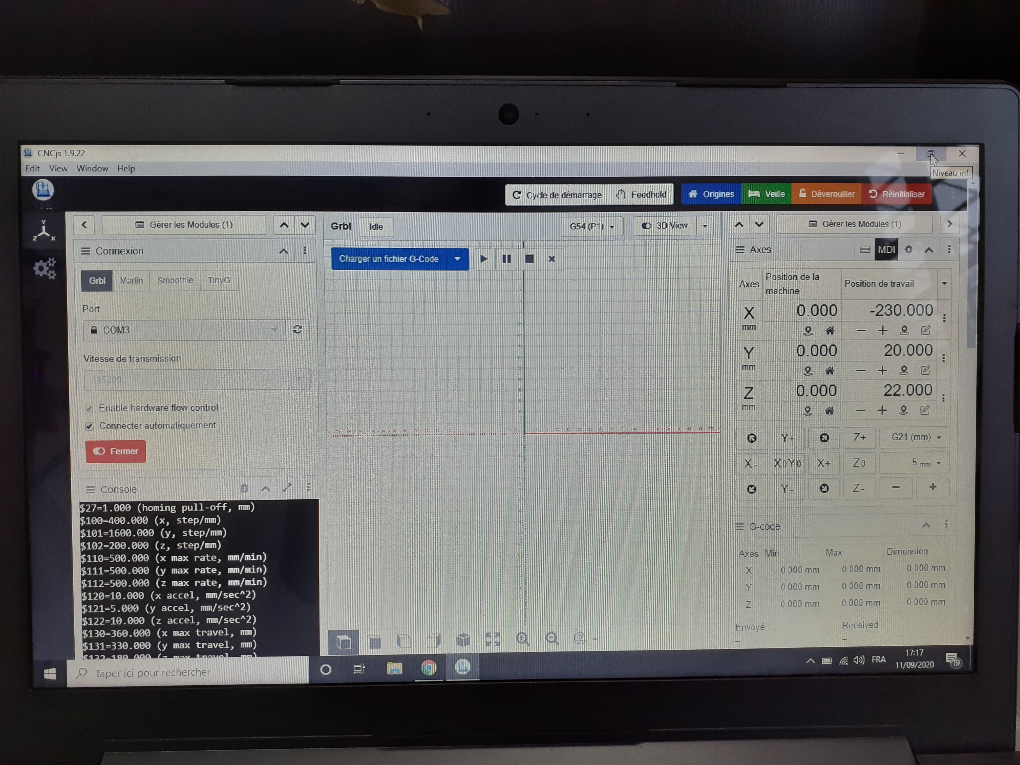
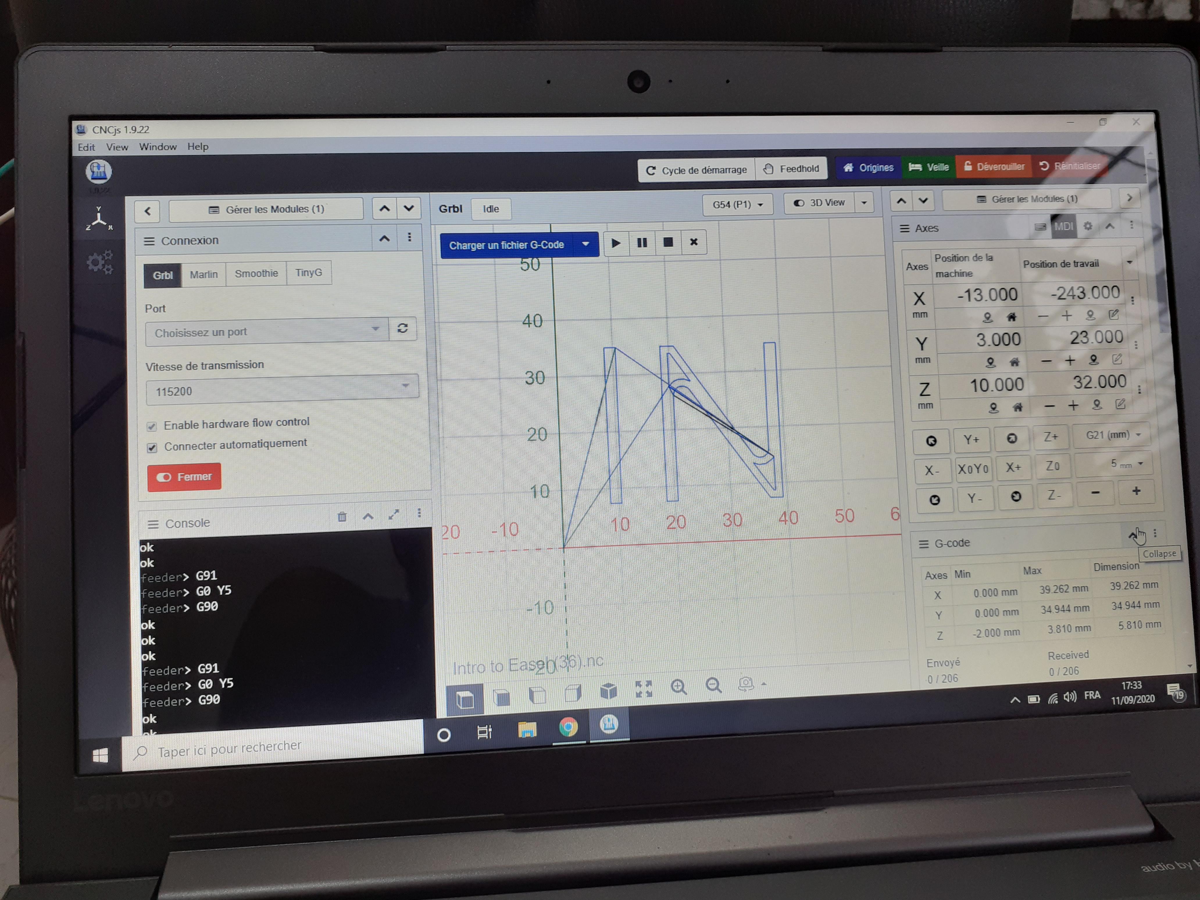
- upload CNCJs (to communicate with the arduino)
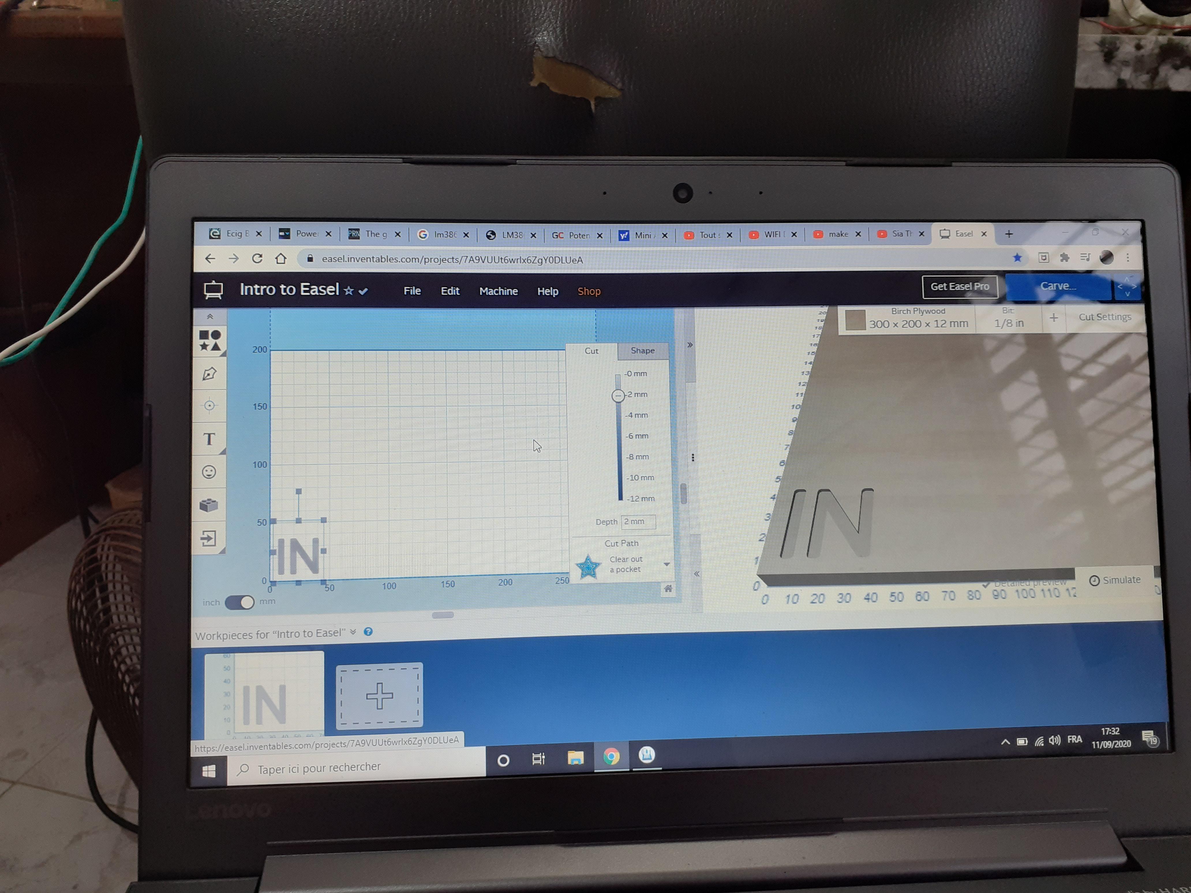
- use EASEL (an online platform to make 2D shapes)
- download files from EASEL and open them with EASEL
- connect your machine to the computer with a USB cable
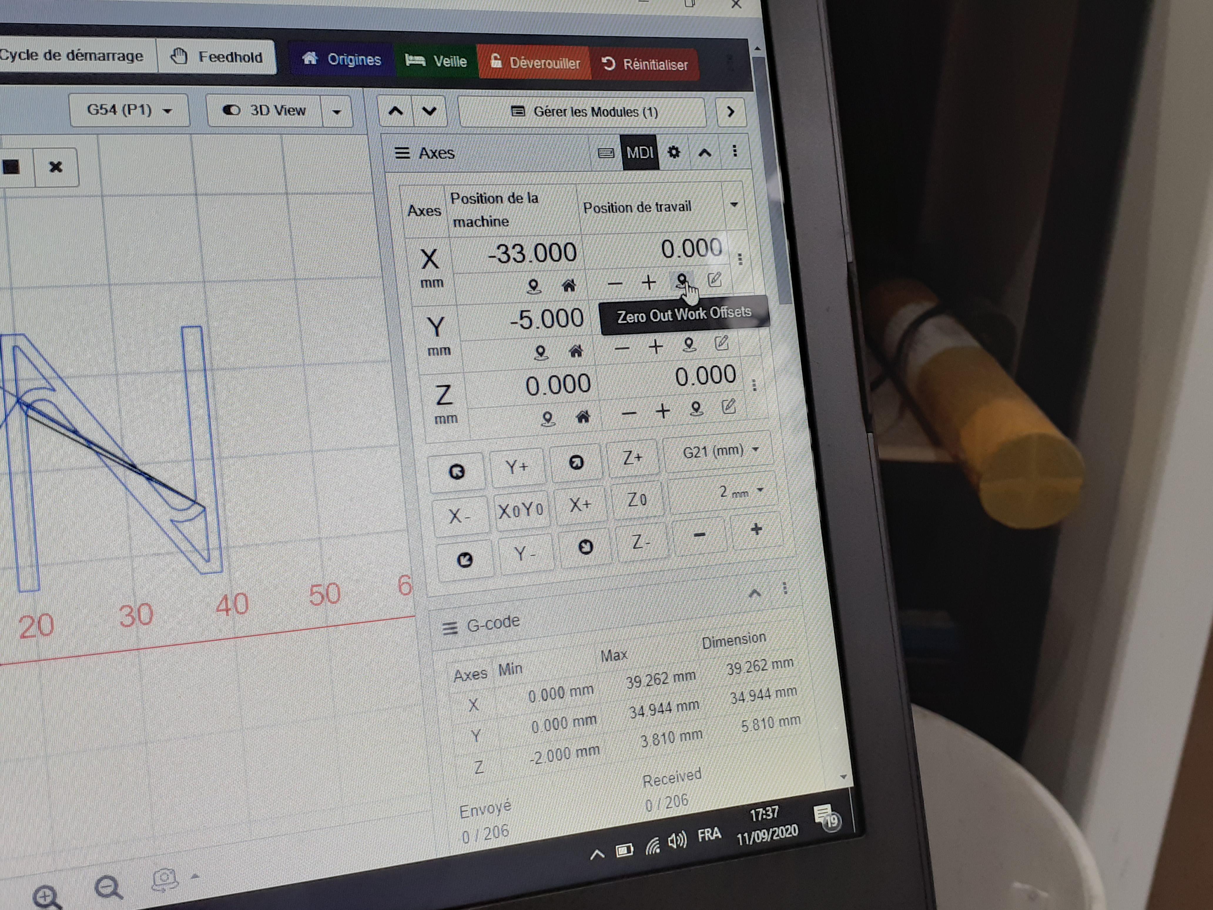
- zero out your machine and get ready for the test
Time for Test
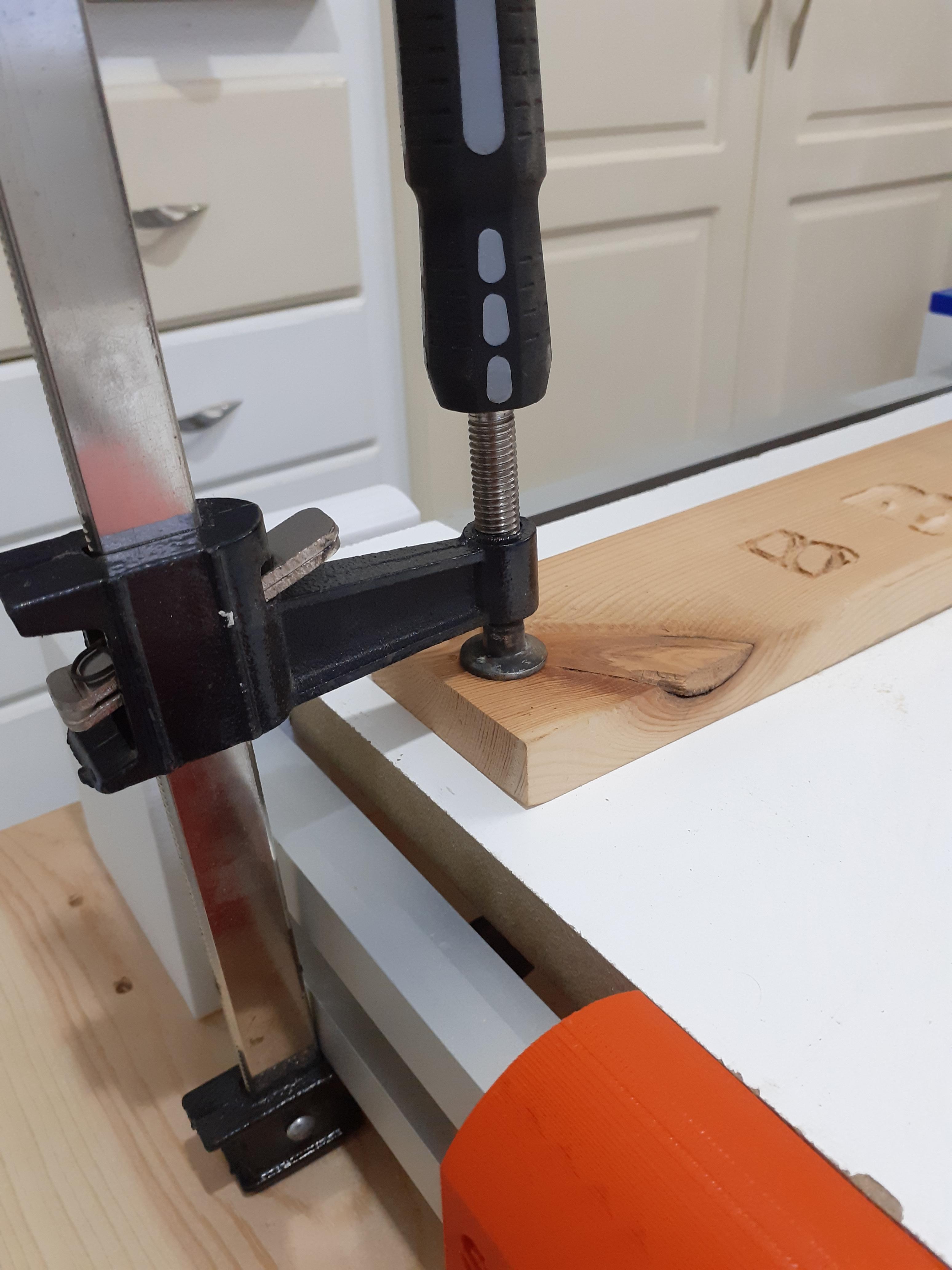
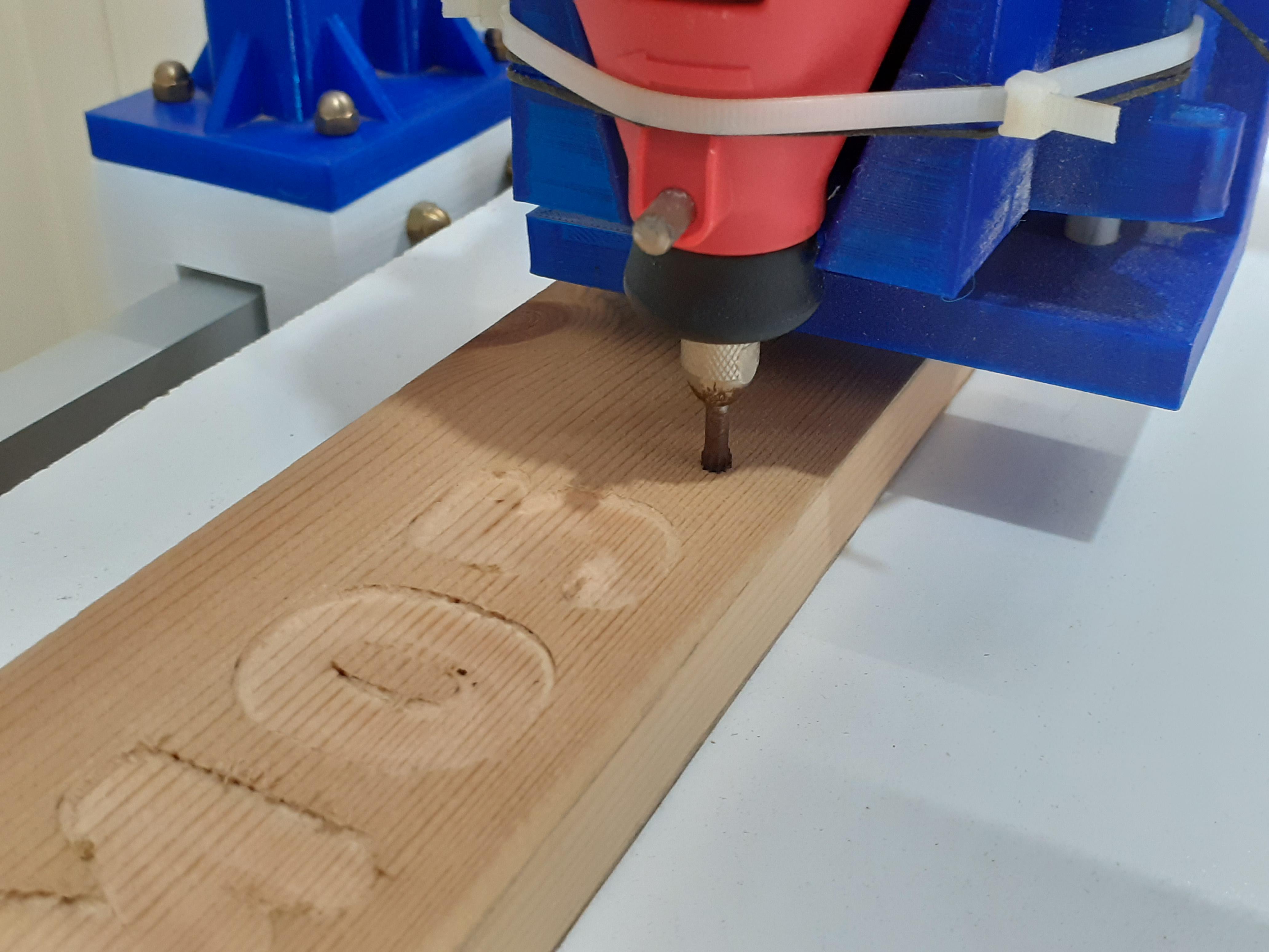
fix the wood you would like to engrave on from both sides with a clamp like this
after following the previous step just press run in CNCJs and watch the magic happen
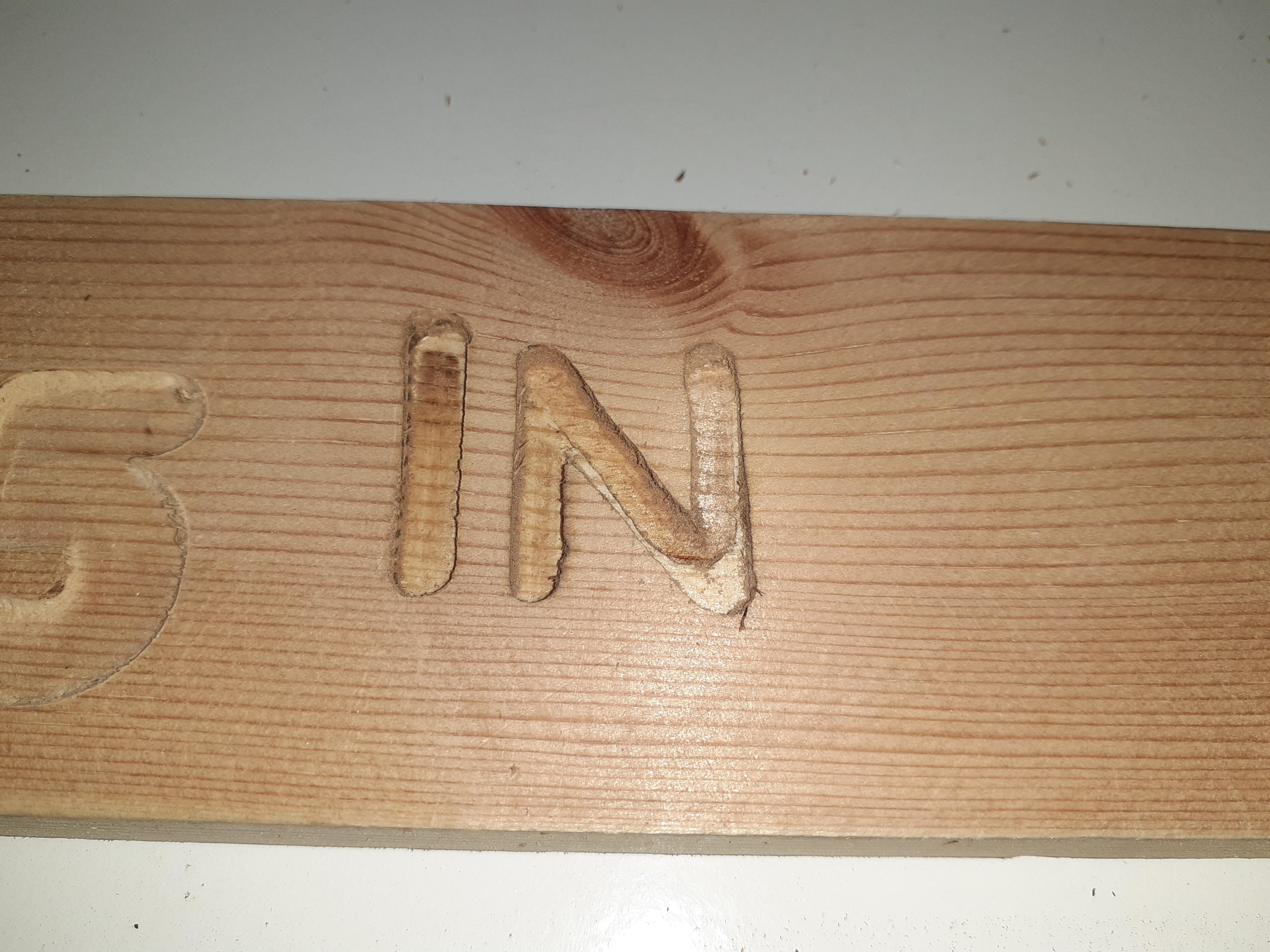
I made IN letters as INSTRUCTABLES
didn't have time to finish the whole word sorry haha
but as you can see it's very accurate
here's a quick video of the machine working
Downloads
Congratulations
Congrats !!! that's it you made it
now enjoy your machine and share with us your machines in the comment and visit my youtube channel for upcoming videos