3D-Printed Clock and Gears
by ewilhelm in Workshop > 3D Printing
59722 Views, 113 Favorites, 0 Comments
3D-Printed Clock and Gears


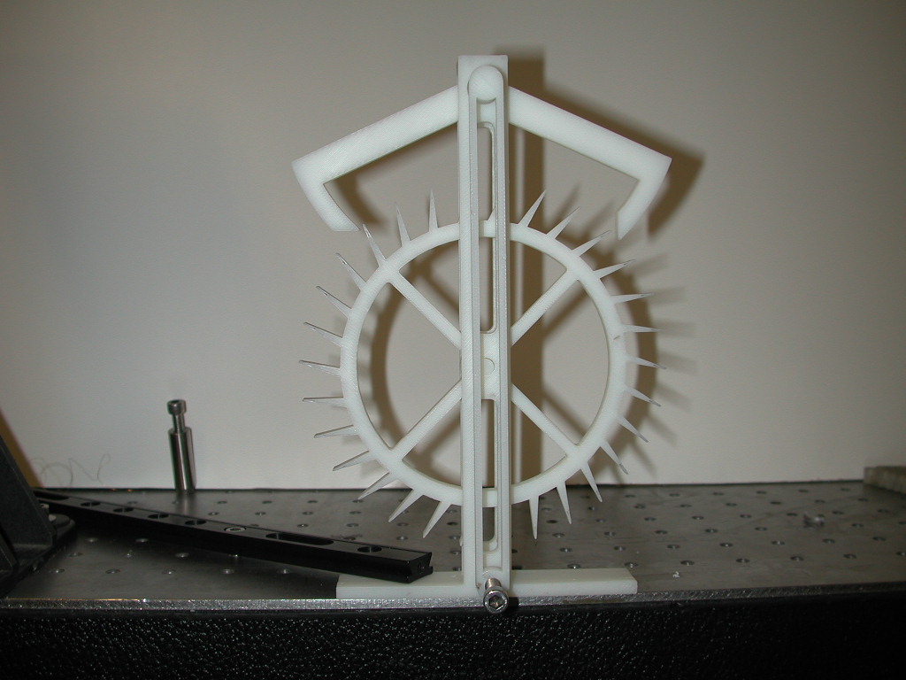
These are the basic components of a clock 3D-printed by a Stratasys FDM 2000. The Stratasys FDM works by laying down "hot noddles" of ABS plastic and a sacrificial material that can be dissolved by water. The hot noodles are printed layer-by-layer and fuse together building finished-quality-level parts. With careful design, you can create captured moving parts, like the interlocking gears shown in the Slideshow.
This project dates to 2001 when I was at the MIT Media Lab. I was big on clocks, and was trying to design a fully 3D-printable clock. I imagined that after dissolving away the sacrificial material, you could wind the clock up and have it start ticking. I printed working gears, springs, and escapements in my attempts to test out each of the required components.
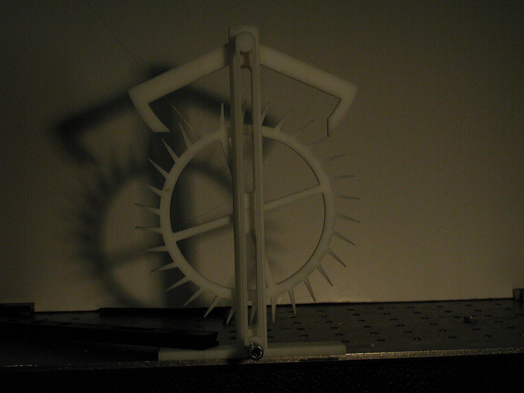
The escapement proved to be the biggest challenge. While it did work, the tolerances on the one shown were not quite good enough for it to work consistently. In the video, I have quite a large weight pulling on the escapement wheel and the pendulum moving briskly, but if the pendulum loses just a little bit of energy and doesn't make a full swing the escapement wheel doesn't lock, and instead, spins freely dropping the weight. The weight, which is out of the video frame, is connected to a spool on the center of the escapement wheel via a white string that is almost in visible in the video. The bed size of the Statasys (about a cubic foot) prevented me from building much larger versions of this escapement where the tolerances wouldn't be as much of an issue.
Obviously, nice escapements and clocks can be built by hand, and I encourage anyone mechanically-minded to at least visualize how escapement works, if not trying to build one yourself.
I've included the complete CAD files from the escapement shown here, so you can use my models as a starting point for your own creations. EJW 3D-printed clock.zip includes Autodesk Inventor files and solid model exports (stl and sat files).