3D Printed Bobbers / Fishing Floats - Design, Make, and Test
7099 Views, 37 Favorites, 0 Comments
3D Printed Bobbers / Fishing Floats - Design, Make, and Test
Let's make a 3D printed bobber/fishing float, test it on the water and catch fish with it. This simple project is an introduction to 3D modeling and printing functional objects on FDM printers.
Supplies
- 3D Printer and filaments.
- Software: Autodesk Fusion 360 or other software that you're familiar with.
- Glue for plastic.
- Fishing gear that you are normally using.
Design the Shape of the Float
First, let's design a 3D printable model of the future bobber / float (I will call it just "float" from now). There are many 3D modeling programs and most of them will work for this task. But in this tutorial, we will be using a program called Autodesk Fusion 360. Fusion 360 is powerful, relatively easy, and free for non-commercial use.
You will need minimal knowledge of Fusion 360 to create a model of the float and if you don't have any knowledge now, you will learn all the skills needed for this project just by following this tutorial (and maybe with a little searching around the Internet).
If you don't have Autodesk Fusion 360 - Download and install it.
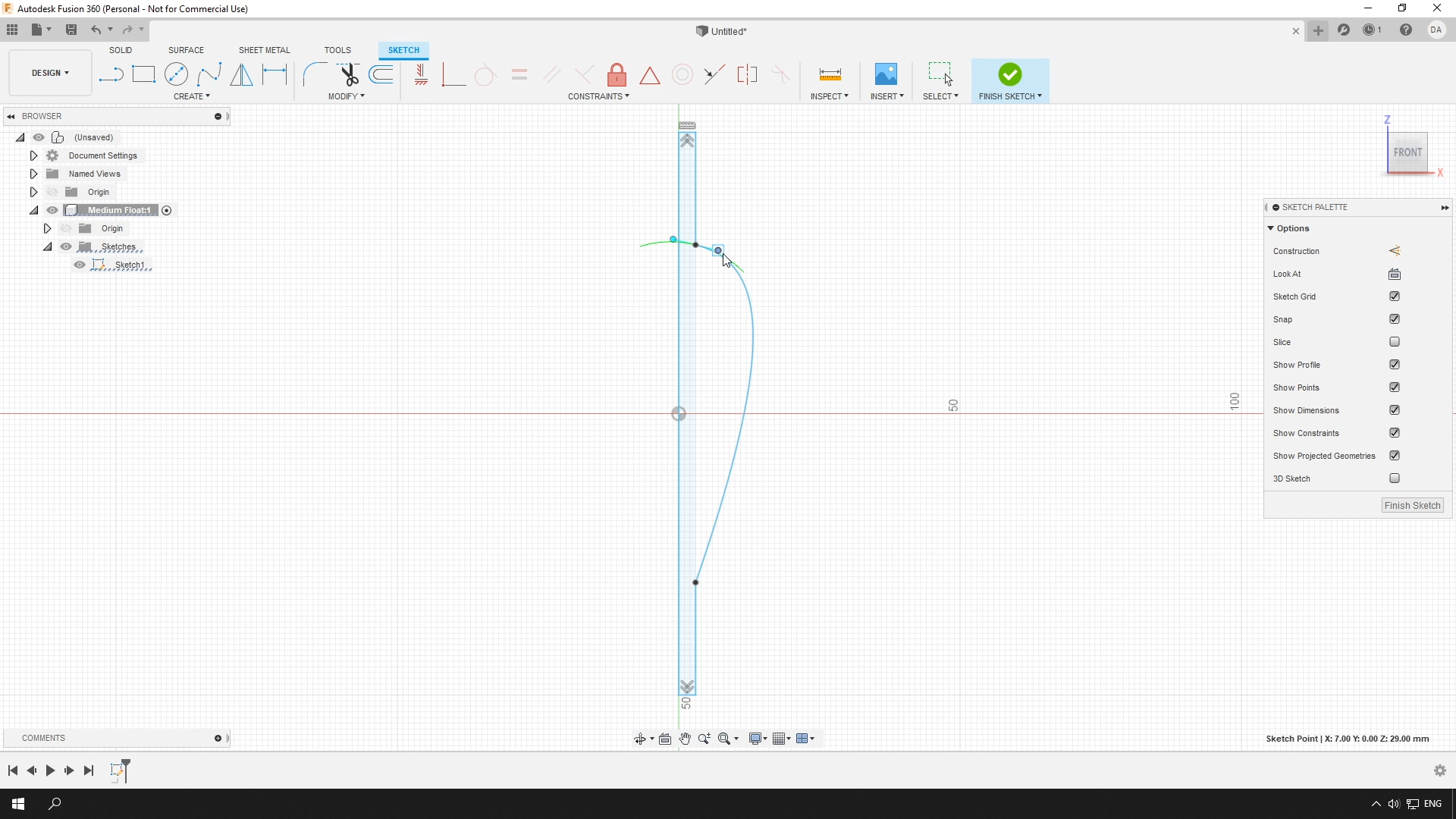
Draw Float's Profile
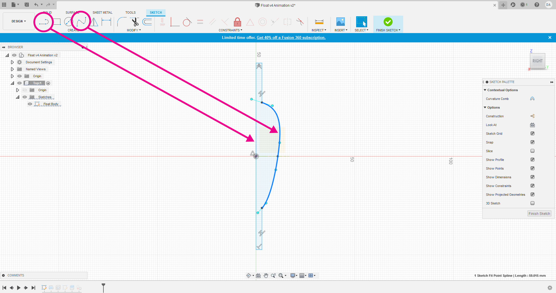
Create a sketch on the front plane (If you don't know how to do this, search for "How to create a sketch on a plane in Fusion 360").
Then draw a profile of the float. You will need just two tools for this, the Line Tool and the Fit Point Spline. Imagine that you need to draw just the silhouette of half of the float.
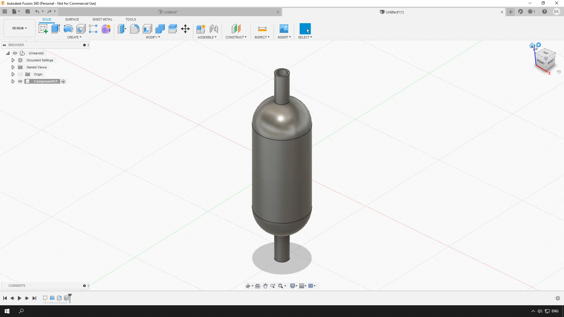
The 3D Float
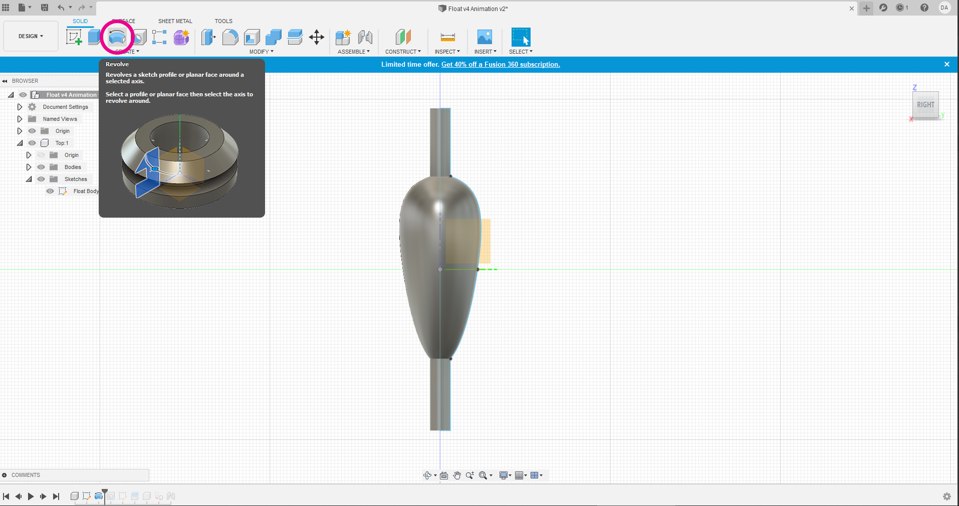
The next tool we will use is called "Revolve". You will need to finish your sketch in order for this tool to appear. And then you will need to revolve your sketch around itself to make the 3D model of the float (How to revolve a sketch in Fusion 360). This is almost it.
Design It Anyway You Like
By the way, you don't have to create this exact shape. You can experiment and make the float of any shape you like. After you've applied "Revolve" you can come back to your sketch and edit the lines and the 3D model will be updated automatically.
Hole Through the Mast
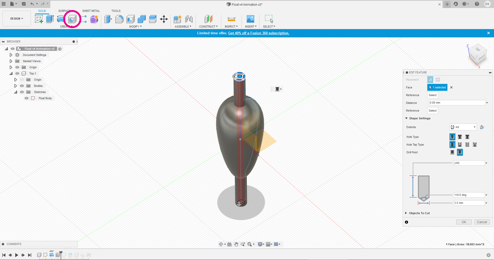
Let's get back to the original shape. Because this float was planned to be the type that is called a running float or a slip bobber (you will see what it is later) - I'm making a hole through the center of it. For this, I'm using a tool called "Hole" (How to create Hole feature in Fusion 360).
Split the Float in Two Parts
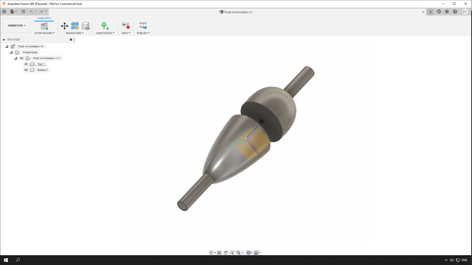
Although it is possible to print this model as is, it will require adding supports* to the model. But I think it will be easier to work with if we split the model into two parts. This way it will be easier to print and to use a different color for each part of the float. Each part will have a flat, stable base to stand on and won't have any overhanging parts. For splitting the model we will need to use the "Split Body" tool.
Create another sketch that will be just a line through the center of the float. Choose Modify > Split Body. Select the body of the float and then select the sketch with the line that will split the body (How to split a body in fusion 360?).
* 3D printing supports are not part of the model and they are used to support the overhanging (in this case) parts of the model during printing (Why are supports needed in 3d printing?).
Slice It!
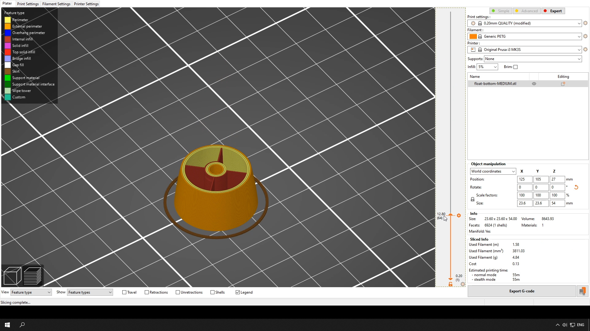
Now we can send the final model to the slicer. If you don't have a 3D printer yet and researching the world of 3D printing - a slicer is a software that converts 3D models into instructions understandable by 3D printers. These instructions are called G-Code (What is a G-Code?).
Slice the model using the settings that are appropriate for your printer and the chosen filament. But keep in mind that we've created a solid model in Fusion 360 and it needs to be at least partially hollow inside. To achieve this, set infill to a low percentage. I sliced my model with 10% of rectilinear infill. To control the thickness of the float walls - change the number of perimeters. I set them to 3.
After that, the file generated by the slicer can be sent to the printer and turned into a physical object.

Now print both parts. If you have more then one color of filament, print the top part in a bright color for better visibility. In my opinion, the best type of filament for this project is PETG, but most of the other types of plastics will work.
Glue the Parts Together
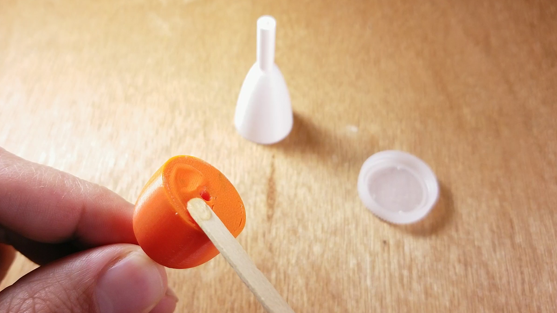
Glue both together. Any type of glue that bonds to plastic will work - epoxy, super glue, and specialized glues for plastics. Check the label on the container.
Attach
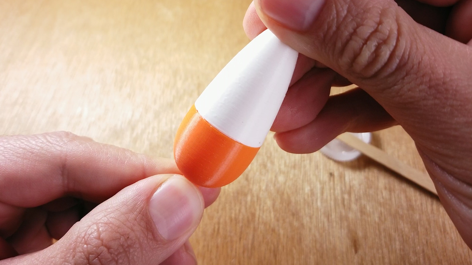
Align and secure the parts with a rubber band and let it set. Wait the appropriate amount of time for the type of glue you are using.
What Is a Slip-Bobber?
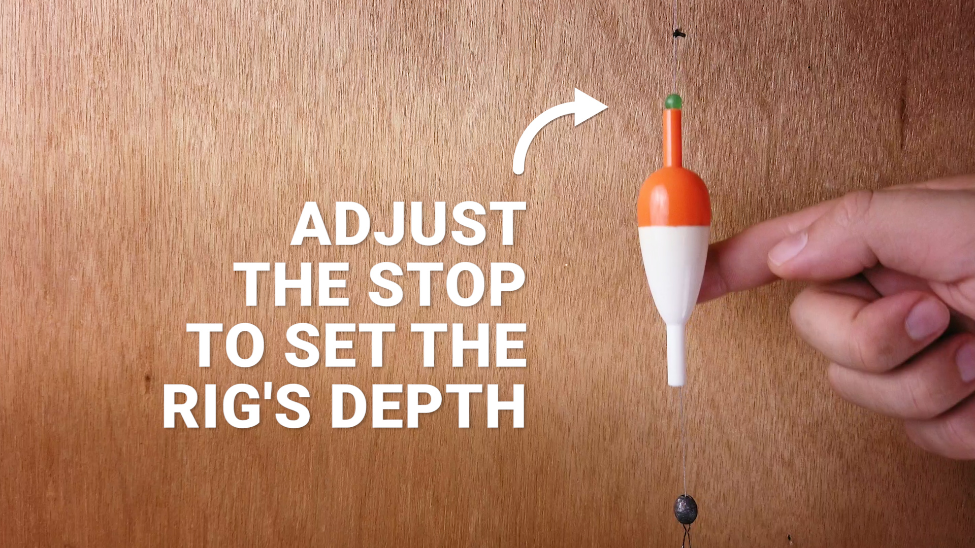
A slip-bobber is a float that slides or slips up and down the fishing line until it hits the stop. The stop controls the depth of your rig, that is, how deep your hook with bait will be under the water. The main advantage of a slip-bobber is that the float is at the botom of your line when you are ready to cast, making casting much easier when you need to fish great depths. When the rig hits the water, the float will slip up the line and will be held by the stop at the desired depth.
Assemble the Rig
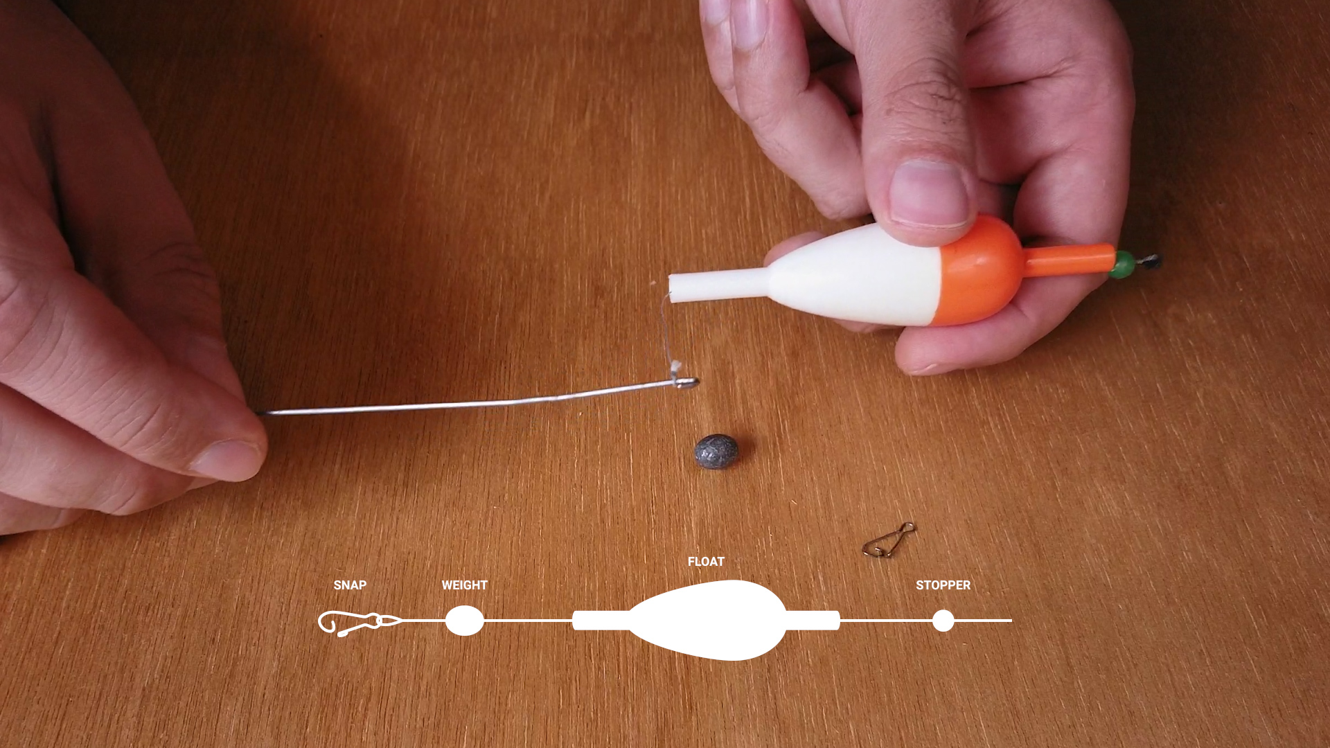
The float-stop goes first onto the line. In my case, the stop is just a rubber band with a bead. Then goes the float, followed by a weight and a snap. The snap will prevent all the pieces from sliding down onto the leader with a hook.
Test 2
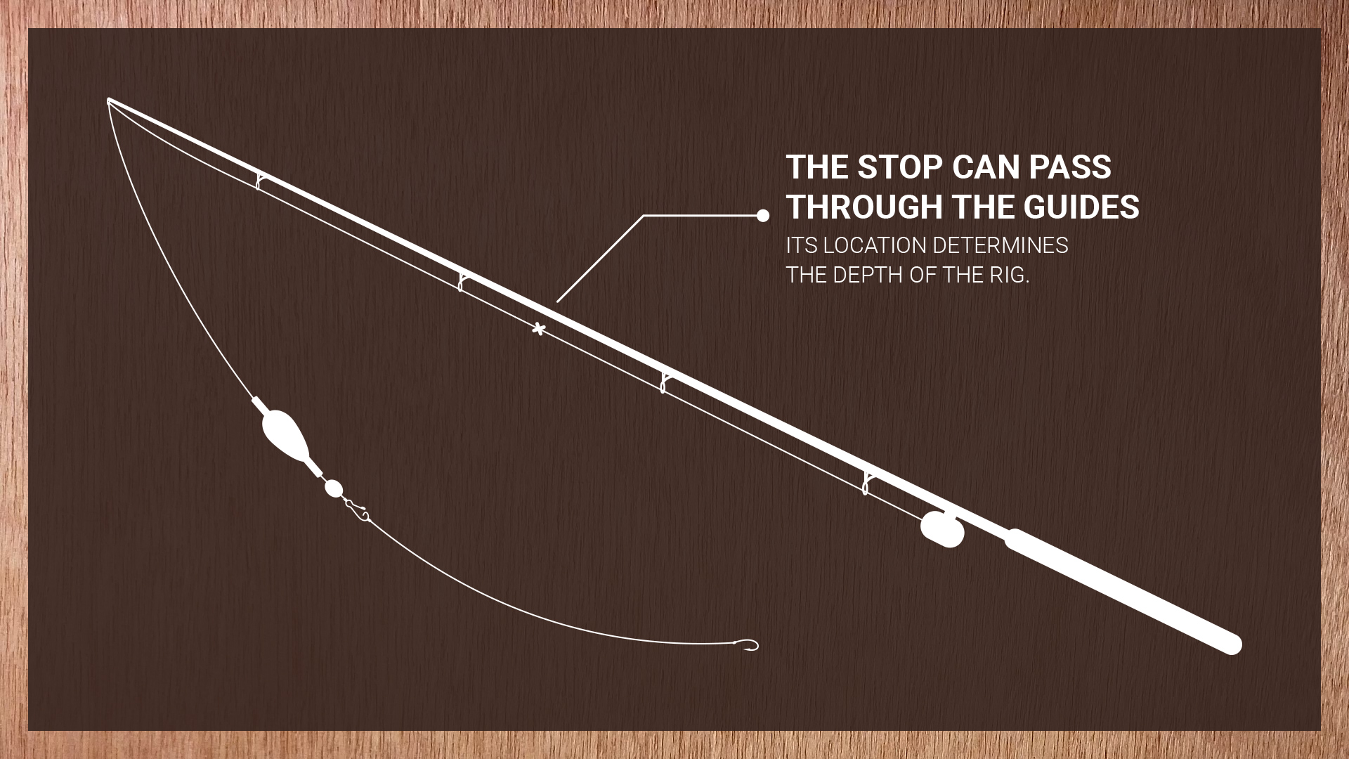
This construction allows the float to slip along the line until it hits the stop. And because the stop can easily pass through rod guides - it's possible to set any distance from the hook by adjusting the stop location. And the maximum depth of your rig is not limited by the length of your rod.
Test at Home
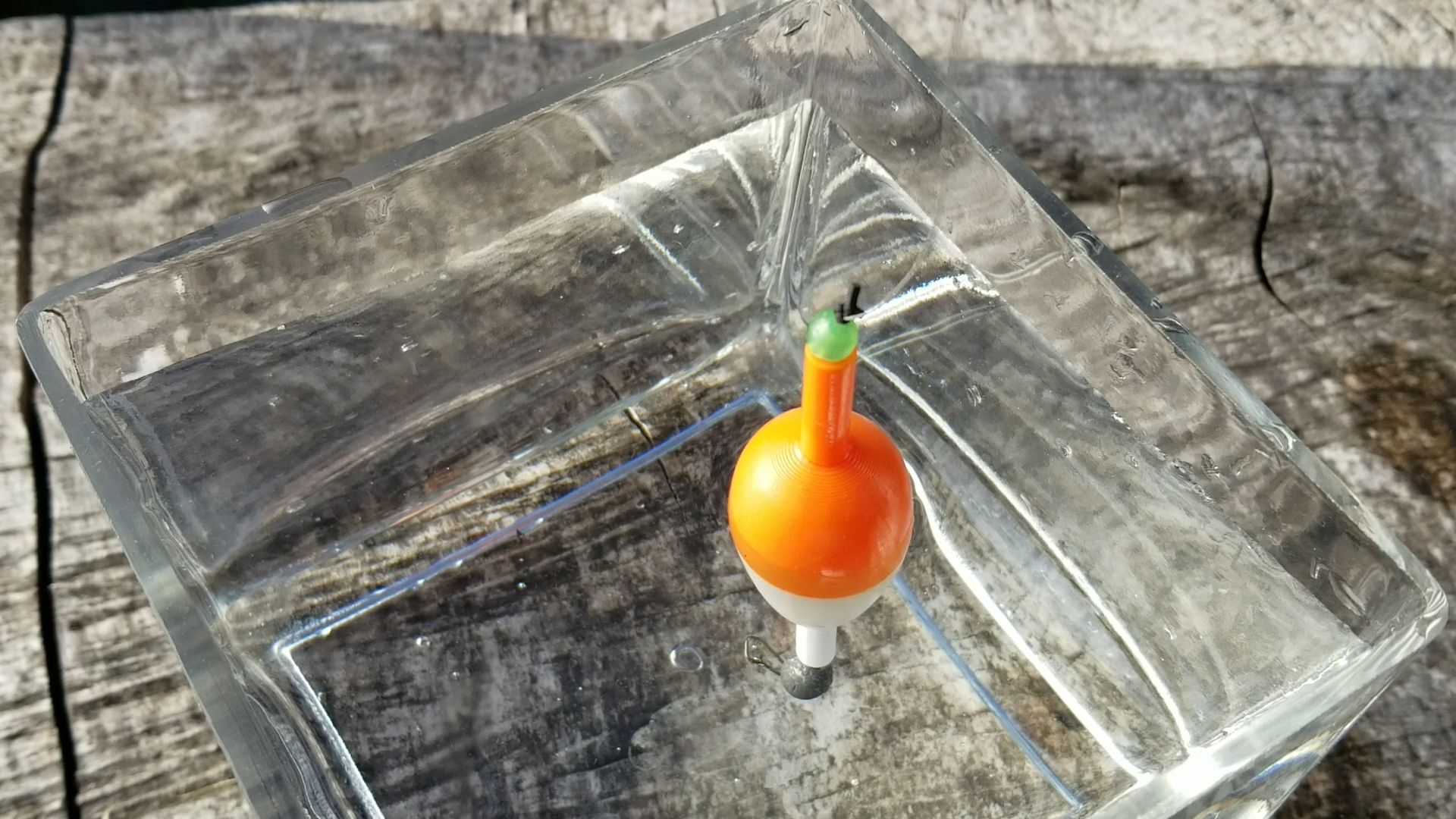
Before going fishing, test the float in a container with water and try a few different egg/bullet weights or split shots to make sure that the float is appropriately weighted.
Go Fishing
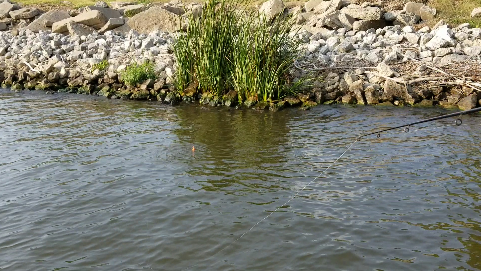
Now you have a functional physical object that you've created out of thin air. Go to a nearby river or lake and test it out!
The Last Step
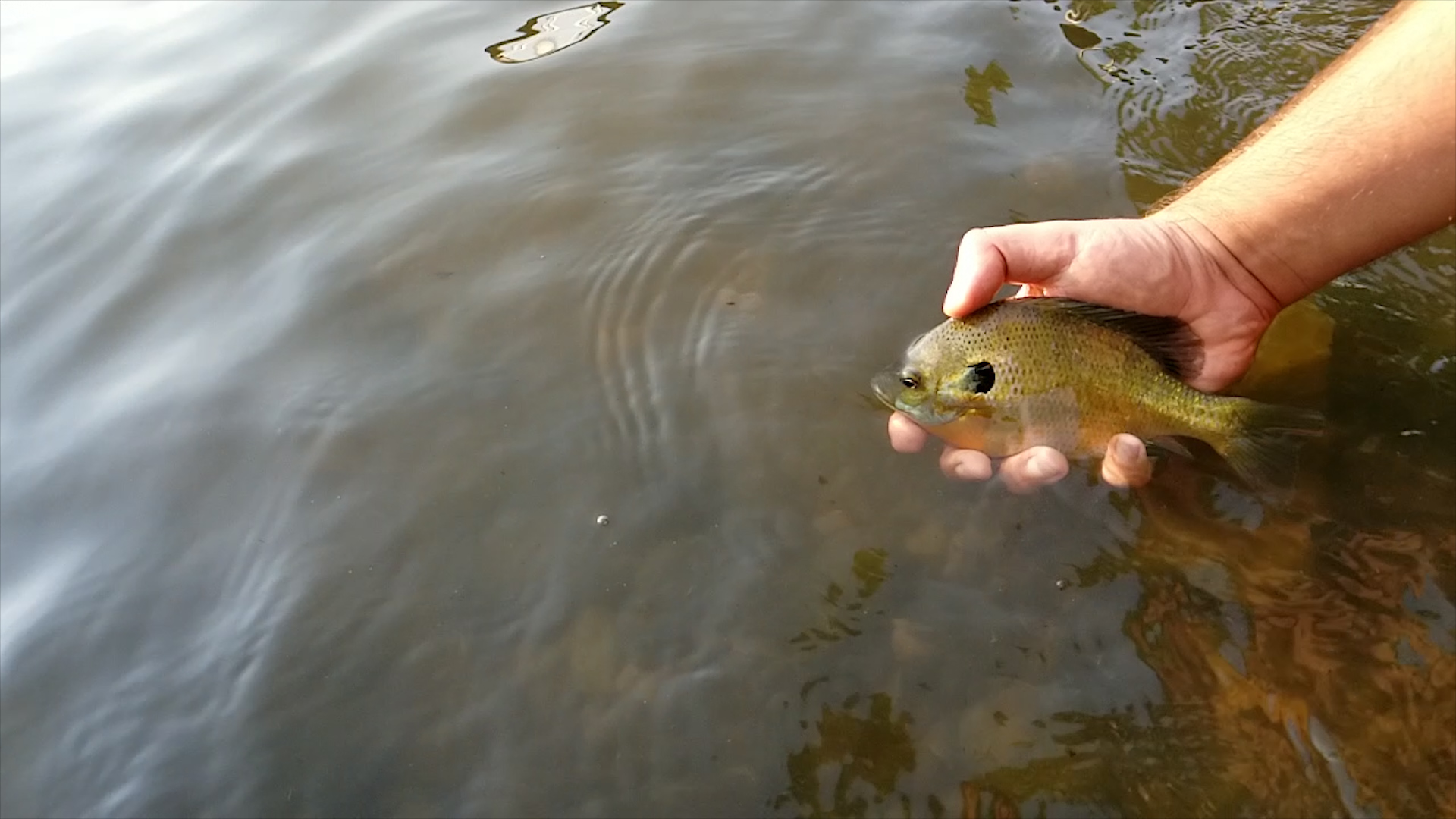
I hope you liked this instructable and will be able to catch fish with your creation! Check my Youtube channel for other projects - youtube.com/aseev