3D Print Desktop Rain Shower Waterfall
by twiesner in Workshop > 3D Printing
7399 Views, 57 Favorites, 0 Comments
3D Print Desktop Rain Shower Waterfall

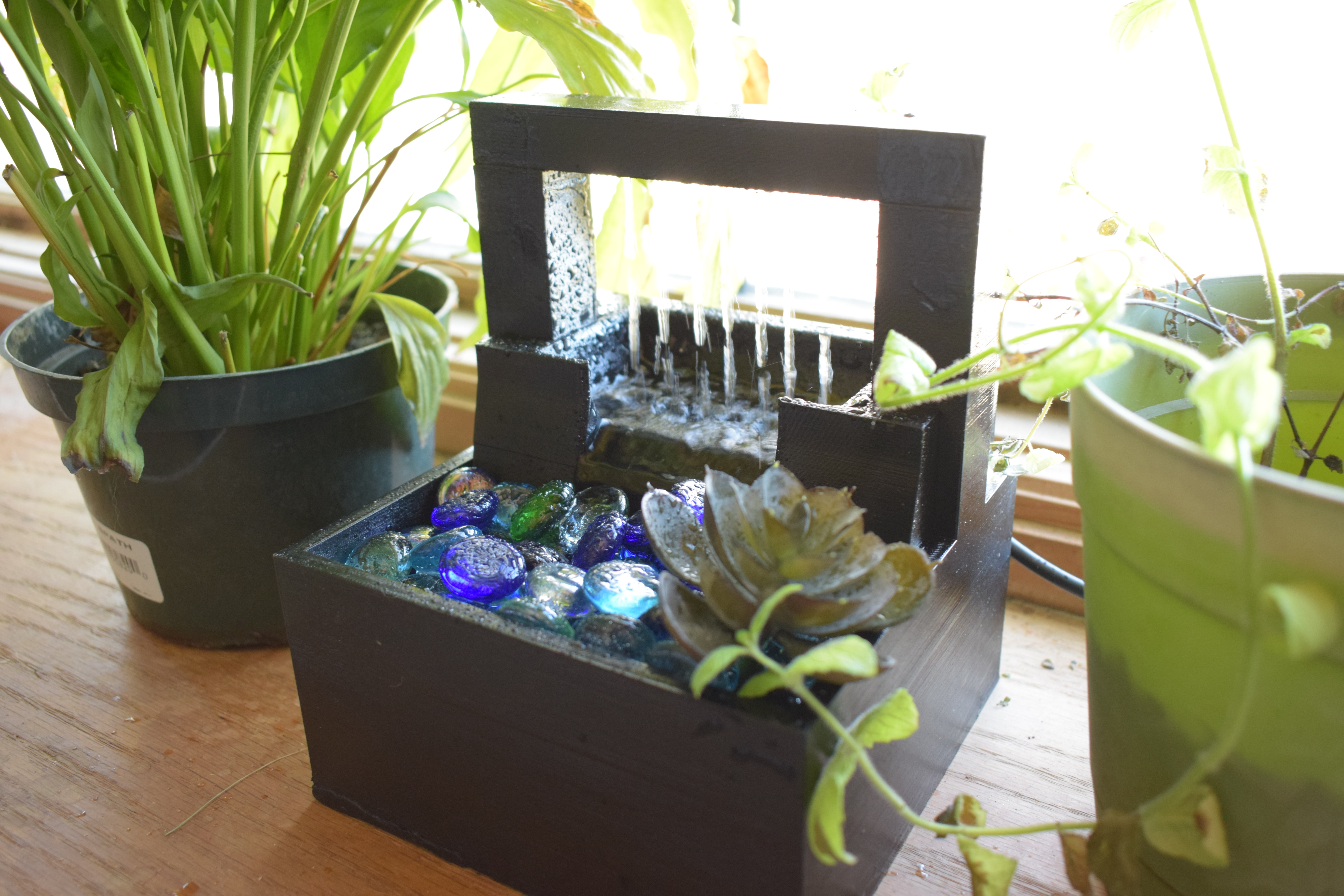
A desktop waterfall is a great way to add some zen and stress relief to the office or living room. The sounds of water can put one's mind into a peaceful state. Alternatively, with a filter, a desktop waterfall can serve as a watering bowl for a pet.
In this instructable I will show how you can create your rain shower waterfall using Fusion 360, a 3d printer, a PTFE tube, and some crafting supplies.
Supplies
- Fusion 360 (or other 3d design software)
- 3D Printer (build volume 8" x 8" x 7" minimum)
- 3D print filament
- Small Water Submersion pump (I used a adjustable 95 GPH 4 W)
- PTFE Tube
- Paint (optional)
- A sealant such a resin or Lacquer
- Small Rocks or Glass Gems
- E6000 Glue
Fusion 360: Modeling the Adaptor
Before beginning, it is best practice to model a mockup of any electronics for size purposes. Don't want to design something only to have it not fit.
The adapter that came with the water pump I order was slightly loose and did not fit the PTFE tube that I had on hand to use. The PTFE tube was a old piece of tubing for a previous 3d printer I had that no longer was working. The tubing I chose to use for this project was a 6 mm outer diameter with a 4mm inner diameter.
1. Under the "Create" menu, select cylinder. Enter dimensions of the insertable part. For my case, the original adapter seemed to have some shrinkage in the plastic in the part that is inserted into the water pump opening(12.4 mm diameter). I added 0.3mm to the diameter and kept the height of the inserted part the same (6.8 mm).

2. Create another cylinder. This should be slightly bigger than the opening hole on the water pump for the adapter. The reference adapter piece measures 14.8mm in diameter with a 1mm in height so I used those measurements.

3. Move current cylinder to top of the insertable cylinder.

4. On top of the "stopper" cylinder, create a 3rd cylinder. This cylinder is the one that will holder the PTFE tube. For 3d printing, I hadded 2.3 millimeters to the size of the outer tube diameter to get the cylinder diameter I needed (8.3). I kept the measured height of the original adapter (11.44mm).
**The 0.3 is the tolerance based on my printer's capabilities and the print settings I plan to use. The tolerance should be adjusted for your printer and nozzle.

5. Under the "Modify" Menu, select the combine tool. Select all the current cylinders change the operation to "Join" to make a solid mesh. Then proceed to create another cylinder. This cylinder is the cutout for the PTFE. Set the diameter to the outer diameter of the PTFE tube (my case 6mm) and set the height to the the length of the entire adapter.

6. Set the operation method to Cut before hitting OK.

7. Using the Fillet tool (located under the Modify menu or shortcut F key), select edges to round out harsh edges. Set the fillet to about 0.25mm.

7. At the bottom of the adapter make another cylinder. I set the diameter to 9mm with a 6mm height with the operation set to cut.

8. Select to inner edge of the most recent cutout. Using the fillet tool, round the edge to the inside is tapered into the opening for the PTFE.

Fusion 360: Create a Mockup of the Water Pump

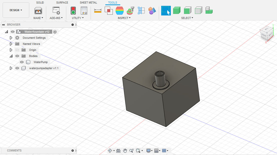
The waterpump I chose is 1.8in x 1.8in x 1.4in. In fusion 360 under the Create menu, select a box and entered the necessary dimensions. Move the adapter piece into relative position.
Fusion 360: Designing the Basin
1. Under the Create menu, select Box. Give the dimensions 152.40 mm x 152.40mm x 76.20 mm.

2. Select the entire box and duplicate it (Ctrl +C then Ctrl +P). Press OK. Select a side face of the box and press the M key on the keyboard. This will bring up the move tool. Move the face inwards 16mm. Repeat for the remain 3 sides. Move the bottom face of the box up 6mm.

3. Duplicate the first box. Move the 4 side faces inwards 6mm. Move the bottom face of the new box upward about 56mm. Duplicate this box and rename it in the Browser to something such as Top. Click the eye icon to hide this copy for later use.

4. Select the combine tool located under the Modify menu. Select the first box as the Target Body and then the other two visible boxes as the Tool Bodies. Set the Operation to Cut and press OK.

5. Create a new box from inside the bottom of the basin. Give it the dimensions of 25.40mm x 25.40mm x 174mm. Move the box to one side of the base with the outer side of the ox aligned with the edge of the outside of the basin. Name this Column in the Browser.

6. Duplicate the column box that was just made. Move the the 4 side faces inwards 3mm. Move the bottom face upwards 155mm. Rename this object in the Browser as Hole.

7. Duplicate the Hole box. Move the 4 and the bottom sides inwards 0.3mm. Rename this mesh Spout Post in the Browser hierarchy and then use the eye icon in the browser to hide the object for now.

8. Duplicate the column box. Move the 4 side faces outwards 0.3mm. In the Browser window rename the object to Column Cut and use the eye icon to hide the object.

9. Combine the Hole and Column object. Use the Mirror function under Create Menu to mirror the column to the opposite side on the basin.Combine the two columns to the basin.

10. On one column, a tunnel will be needed for the PTFE to go through to filter the water up from the basin and into the spout. Inside one of the columns make a Cylinder that cutouts out 6.5mm (or slightly bigger than the PTFE you are using) by about 125mm deep.

11. Create another 6.5 diameter cylinder that is about 25 mm in height. Using the Move tool (Hotkey M) rotate the cylinder about 45 degrees. Move the cylinder so the top intersects into the tunnel within the column.

12. Using the Draft tool located under the Modify Menu, select the top end of the rotated cylinder as the Plane and the side of the cylinder for the Faces selection. Angle the draft about 15 Degrees.

13. Select the inside face of the bottom of the column tunnel. Move and angle the face to align close with the tapered cylinder.

14. Using the combine tool, set the Basin as the Target Body and the tapered cylinder as the Tool Bodies. Set the operation to Cut and press OK.

15. Use the Fillet tool (Hotkey F) to round out the opening and the inside bend for the tunnel.

16. On the back side of the basin there should be a opening for the water pump power cord. Create a cylinder in the top side of the back wall of the basin. Set the diameter to 20mm and height to about 21mm. Set the operation to New Body. Align the cylinder so one face is aligned with the outer wall face with the cylinder pointing inwards.

17. Create a box half way through the cylinder that is 20 mm x 22 mm by 21mm.

18. Combine the cylinder and the box to the basin as a Cut operation.

19. Use the Fillet tool to round the inside edge.

20. From the bottom of the inside of the basin, create a new cylinder. Set this to about 20 mm and extend the height to about 70mm. Move the cylinder so it cuts into the ledge of the back wall but not into the exterior wall.

21. Use the Combine tools as the Cut operation into the basin.

22. Use the Fillet tool to round the top edge of the cutout.

Fusion 360: Designing the Basin Top
1. Unhide the Top layer from the Browser. Resize the height of the box to about 4 mm height.

2. Create new box that it about 44mm in height. Make the width the same as the Top and half the length.

3. Duplicate the previous box. On the front and back of the box, move the faces inwards 10mm using the move tool. Move the 2 side faces inwards 30 mm. Move the bottom face upwards 20 mm.

4. Combine the two boxes. Set the smallest box as the Tool Bodies with, the tallest as the Target Body, and the Operation as Cut. Press ok. Rename this mesh in the Browser as Small Basin.

5. Create a new box in the middle of the front wall of the small basin. A opening of about 60 mm in width by 15 mm in height is needed. Set the operation to Cut.

6. Under the Modify menu, select the draft tool. Select the top face of the resulting cut as the Plane and select the inside wall of the front wall as the Faces. Rotate the angle about 25 degrees.

7. Select the face of the rotated wall. Move it inwards about 5 mm to thicken the front wall.

8. Combine the small basin to the top mesh. Rename layer in browser if needed to Basin Top,

9. Unhide the Column Cut layer from the Browser. Mirror the column to the opposite side. Combine the two columns to the Basin Top with the Basin Top as the Target Body and the Operation as Cut.

10. Select the face of the outer part of the front wall of the small basin. Rotate the face slightly (about 15-25 degrees).

11. Select the lip face of the small basin. Rotate this face about 25 degrees.

12. Select the inside and outside edges of the lip of the small basin. Chamfer the edges about 2 mm.

13. Rotate the 3 other inside side faces of the small basin. (about 15 -25 degrees).

14. Create a cylinder in the middle of the backside of the Basin Top. Set the diameter to 20 mm with a 21 mm height.

15. Create a box halfway through the cylinder. Set the dimension to 20 mm x 22 mm by 21mm.

16. Combine the box and cylinder as a cut operation to the Basin Top.

17. Create a few boxes under the small basin about 22 mm in height. The goal is to make room for the PTFE tube. Combine these boxes as a cut operation to the Basin Top.

18. Use the fillet tool to round out the inside edges of the space.

19. On the side where the PTFE tube needs to filter up into the column, make a box that cuts into the underside cavity but not into the small basin.

20. Use the Fillet tool to round out the edges.

21. Make series of cylinders about 6 mm in diameter.

22. Combine the series of cylinders to the Basin Top as a cut operation to make a drainage tray.

23. Round the edges of the drainage holes about 2 mm.

24. Extrude the top of the small basin walls to create a splatter barrier (Hotkey E). Use the Fillet tool inside the Small basin to create more of a bowl shape.

Fusion 360: Designing the Spout
1. Create a new box (25.4 mm x 152.4 mm x 25.4 mm) a top of the columns of the basin. This needs to stretch from column to column. Name this box Spout in the Browser hierarchy.

2. On the left side of the spout, create a cylinder with a 6 mm diameter with a 104 mm height. Center the cylinder so it is in the middle of the spout and 12.4 mm from the edge.

3. Unhide Spout Post from the Browser. Mirror the Spout Post to the opposite side and join both posts to the Spout using the Combine tool.

4. Create a new cylinder in the middle of one of the posts on the side the PTFE tube needs to be on. Set the diameter to 6.5 mm. Align the new cylinder to intersect with the horizontal.

5. Create a 15mm Sphere. Move the sphere to cover the intersection of the two cylinders.

6. Under the Modify menu, select Scale. Select the sphere and set the scale type to Non Uniform. Scale the y axis to about 0.72mm.

7. Select the sphere and the horizontal cylinder. Move the objects so the horizontal cylinder is about 5.7mm from the bottom of the spout edge.

8. Combine the two cylinders with the sphere. Use the Fillet tool to round the edges leading into the sphere.

9. Combine the inside tubing to the spout as a Cut operation.

10. Create a 2mm cylinder at least 15mm in height. Move the cylinder to intersect with the horizontal tube inside the spout. Duplicate the vertical cylinder and move it to the side 8mm. Repeat duplicating and moving cylinders 5 more times.

11. Combine the 7 vertical cylinders to the spout as a Cut operation.

12. Using the Fillet tool, round out the inside edges of the vertical openings.

Fusion 360: Optimize Tips
1. Using the move tool, you can shorten the inserts of the spout into the column. This will save on 3d print filament and make inserting and removing the spout easier.

2. Broad prints are prone to warping when printing. Making a series of flatten cylinders to use as cutouts in the base of the Basin, will help minimize warping and make the Basin print easier to remove. Will also reduce the amount of filament needed when designed to print support free.

3D Print the Pieces
I printed the pieces in a PLA filament on a Wanhao Duplicator I3 clone (Powerspec Duplicator I3 from Microcenter). Print settings should be tweaked to best suit your 3d printer.
Water Basin

Layer Height: 0.3mm
Speed: 55 mm/s
Temperature: 225C
Fill: 18%
Internal Fill Pattern: Full Honeycomb
Supports: No
Rafts: No
Basin Top

Layer Height: 0.3mm
Speed: 55 mm/s
Temperature: 225C
Fill: 18%
Internal Fill Pattern: Full Honeycomb
Supports: Yes
Rafts: No
Spout

Layer Height: 0.3mm
Speed: 55 mm/s
Temperature: 225C
Fill: 18%
Internal Fill Pattern: Full Honeycomb
Supports: No
Rafts: No
Final Print

Prep and Assemble

1. Once the pieces to the fountain are done 3D printing, it is now time to seal the pieces so water cannot get through the layers of the print and leak out. This is also to prevent bacteria from getting into the layers and molding after a few uses of the fountain. Use a resin epoxy or a lacquer paint
2. After painting, check fittings of the pieces. Sand down parts if needed due to excess paint.
3. Around the water pump adapter apply a little E6000 glue around the seal to lock the adapter to the pump so water cannot escape the between the water pump and the adapter. Apply around the the PTFE tube if needed.
4. Thread the PTFE tube up the column. Cut off any excess PTFE.

5. Slip the Basin Top on over the columns and slide into place.
6. Apply E6000 glue inside the column post hole around the PTFE tube. This is to create a water tight seal around the PTFE tube. Add a little glue to the top where spout will meet the columns to ensure water cannot escape. Insert the Spout into the columns. Let dry for 24 hours.

7. Fill Basin with water. Power the fountain and check for leaks.
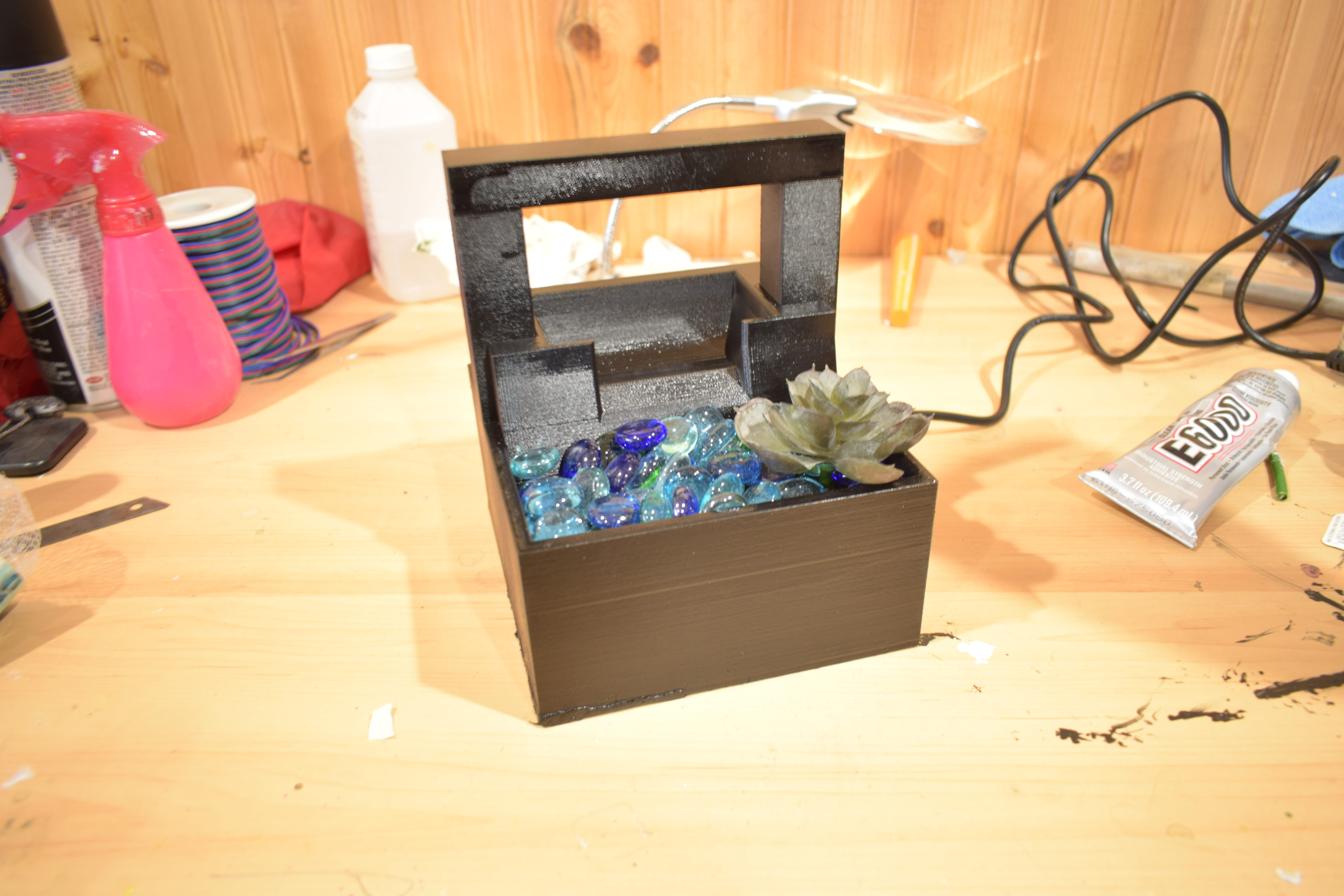
8. Add decorations to cover the drainage holes such as small rocks or glass gems.
Final Result

Stl files made in this project are available for free download on Myminifactory.com