3D Designed and Printed Coded Message Device With a CPX
by bryanlallo in Circuits > Computers
76 Views, 1 Favorites, 0 Comments
3D Designed and Printed Coded Message Device With a CPX
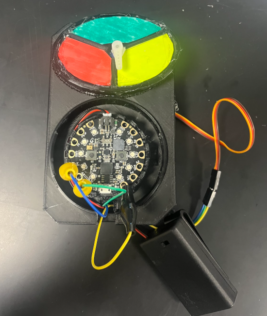

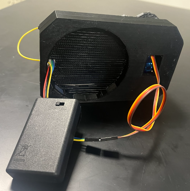
This communication device combines innovative thinking and use of different physical materials as well as technology-based circuits created by three college students and then redesigned by another group of three students. The second group of students changed nothing about the physical device but modified the coding of the project to make it work more affirmatively.
The Coding was changed from JavaScript to Python for better efficiency results. The codes in the original version did not work the way it was intended to work, but with new coding updates, everything should work great!
Modified by:
Bryan Lallo
Kaitlyn DiLoreto
Gregory Noroian
Jessica Parent
Supplies
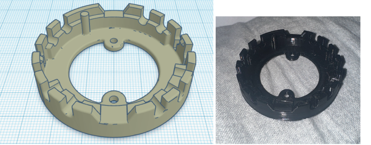
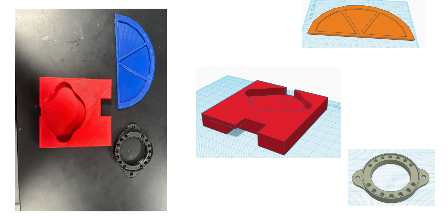
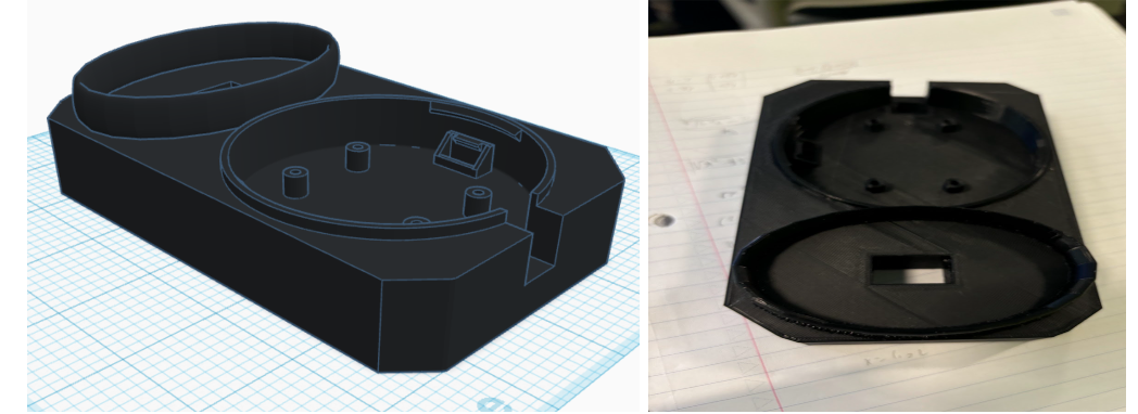
In this project, there are a few materials that are seen constant throughout the mechanism. First, there are hard shell 3D printed parts that were made with a MakerBot Sketch machine and filament for it. There is also a CPX which is the brain of the device. There is also a wire system to power everything through a battery pack which is also included in the project.
Assembly Step
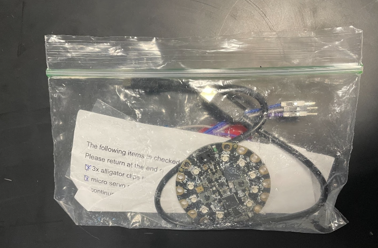
Remove all parts from the bag (the plastic 3d printed piece itself will not require assembly, just the CPX and motor).
Assembly Step
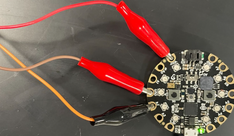
To connect the alligator clips to the CPX:
- Connect the RED wire alligator clip to Vout
- Connect the BROWN wire alligator clip to GND
- Connect the YELLOW wire alligator clip to A2
Assembly Step
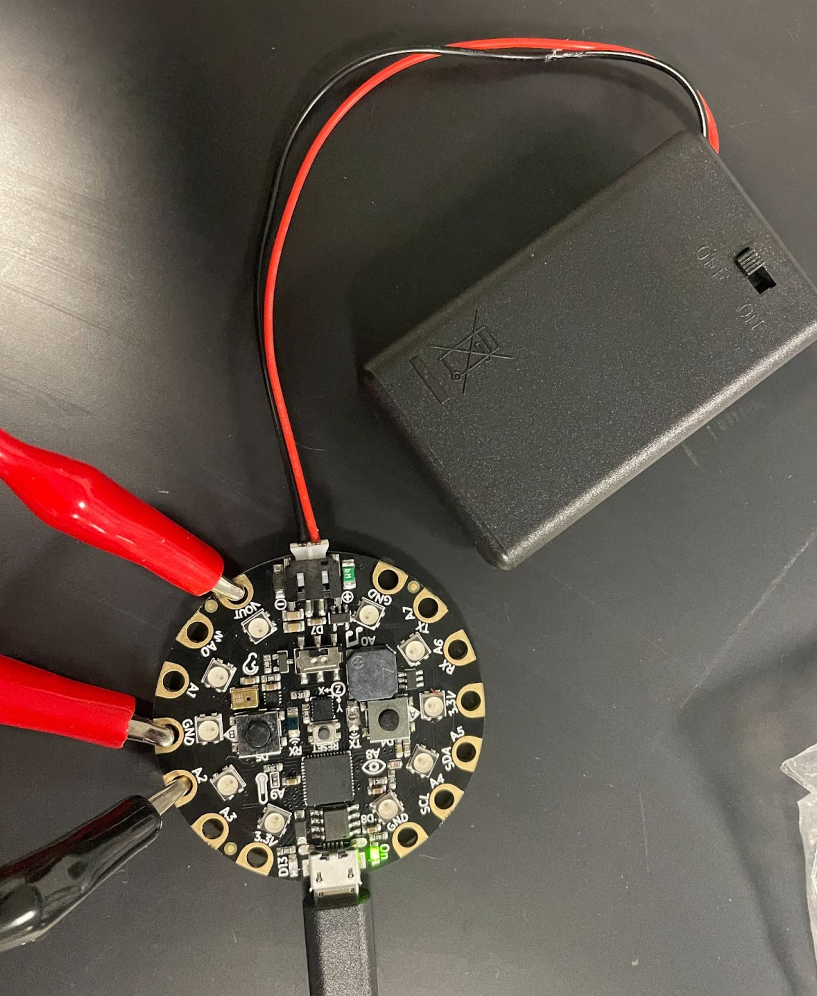
- Plug the black battery pack into the CPX.
- There are two places to insert that cord, insert it into the black square on the CPX.
- Switch the battery pack to on
Assembly Step
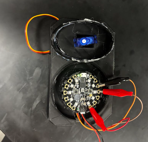
Place the CPX with the wires attached to the CPX mount on the 3d printed prototype
Assembly Step
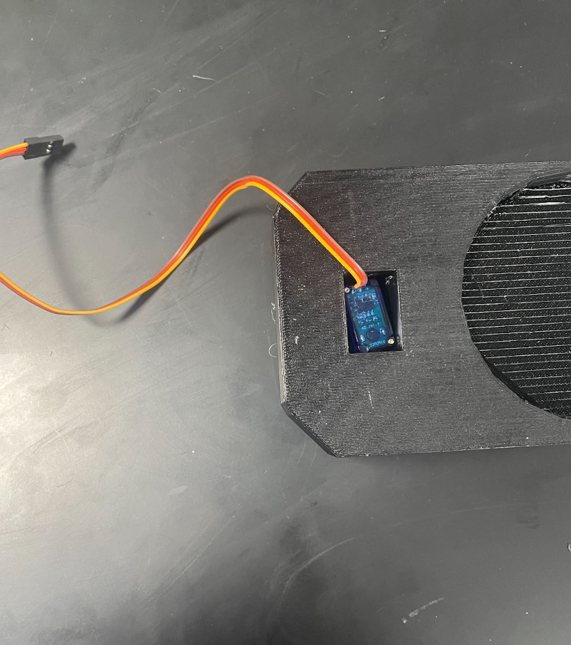
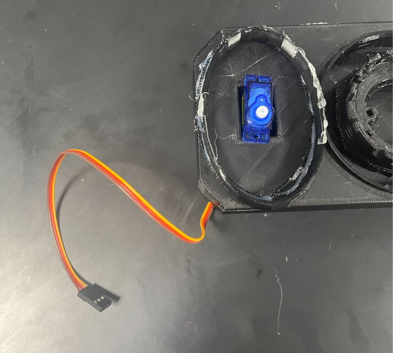
Thread the servo (Blue box) through the top of the prototype through the tiny rectangular hole, with the wires coming out of the bottom of the prototype.
Assembly Step
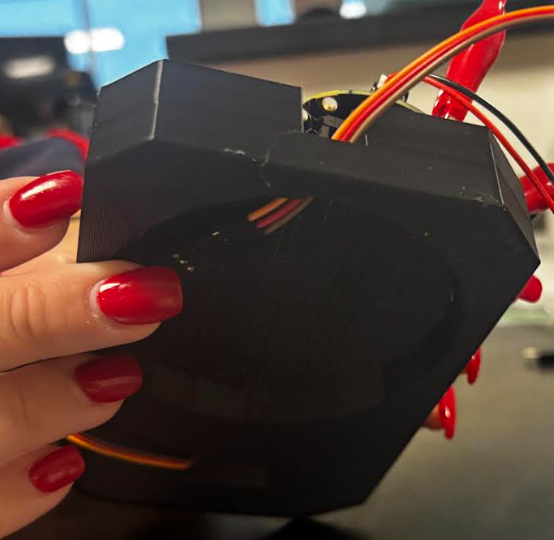
Thread the wires connected to the alligator clips through the hole on the front of side of the prototype.
Assembly Step
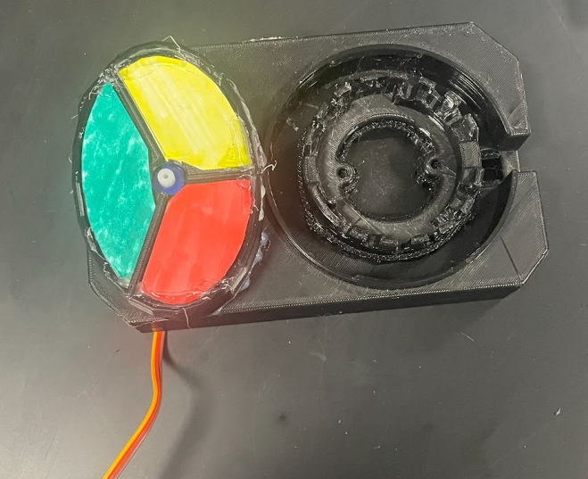
- Cover the servo with the colored case (red, yellow, and green)
- The RED and the YELLOW are facing inward, with the GREEN on the outside
Assembly Step
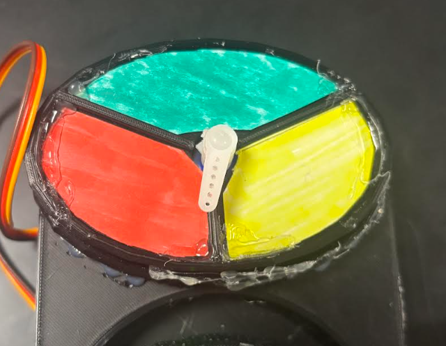
Then attach the white arrow to the center hole in the covered case facing it on the RED side closer to the line between RED and YELLOW.
Assembly Step
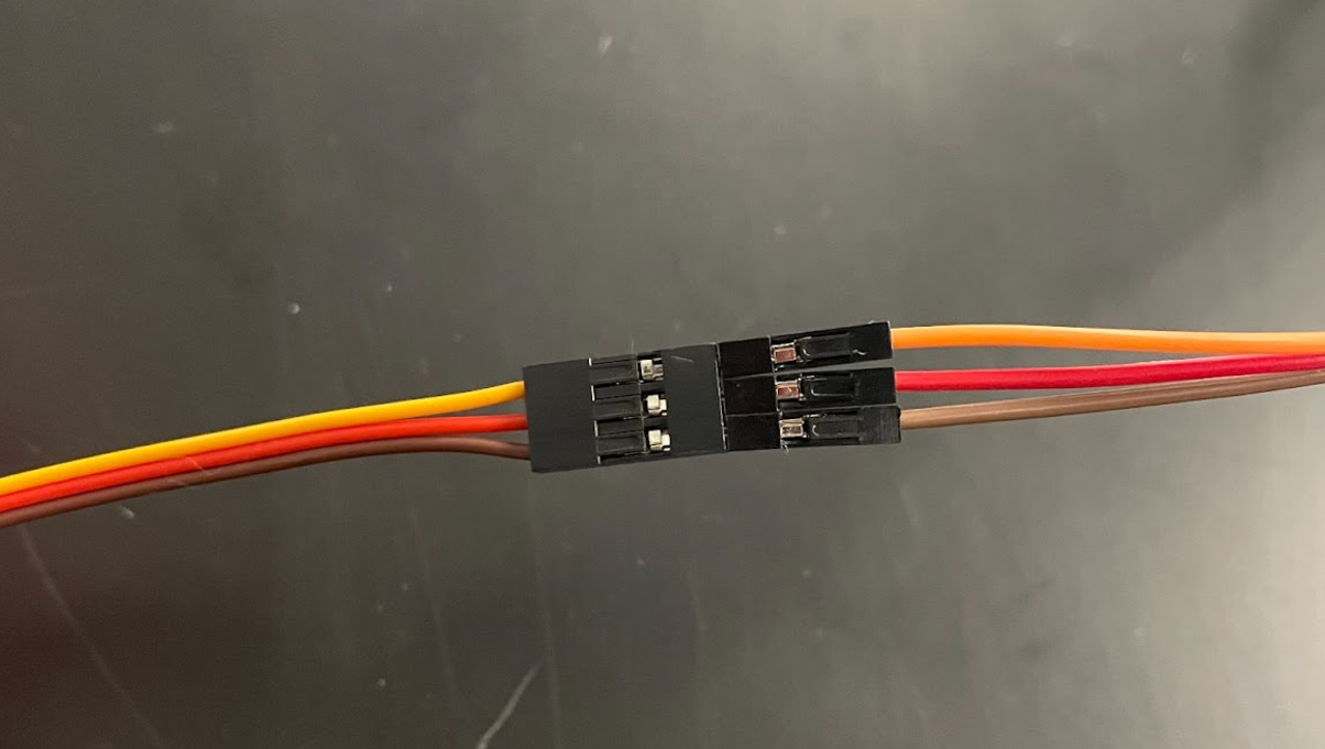
To connect the wires from the alligator clips to the servo
- Connect the BROWN wire from the alligator clips to the BROWN wire from the servo.
- Connect the RED wire from the alligator clips to the RED wire from the servo.
- Connect the YELLOW wire from the alligator clips to the YELLOW wire from the servo.
How to Use
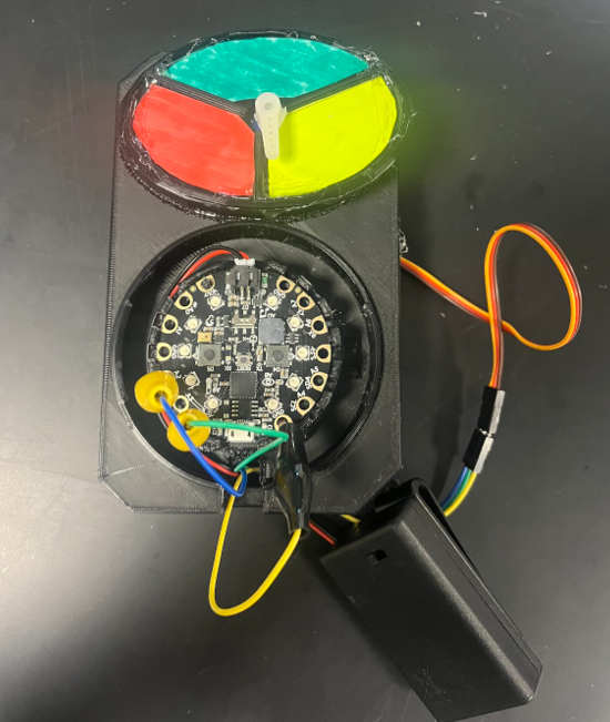
- By pressing button A
- The CPX lights up RED
- The servo arrow points to RED
- The user decides what this color communicates
- By pressing button B
- The CPX lights up YELLOW
- The servo arrow points to YELLOW
- The user decides what this color communicates
- By pressing BOTH buttons A and B at the same time
- First, the CPX releases a siren sound
- Second, the CPX flashes BLUE and RED
- The user decides what this color communicates
- By shaking the device
- The CPX flashes 5 WHITE lights
- The user decides what this color communicates
That's It!

Enjoy your new device you just built! Pat yourself on the back!