3D Audio Graphing (MATLAB)
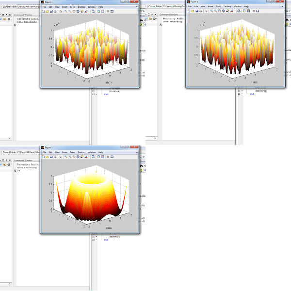
How are audio data signals affected by a 3 dimensional sine wave?
In this project we examine the effects that recorded audio data stored in arrays produces when displayed on a 3D sign wave graph.
For this we use MATLAB and only 22 lines of code. You WILL need to edit this code for the specifications of your computer as well as your own preferences.
You will need:
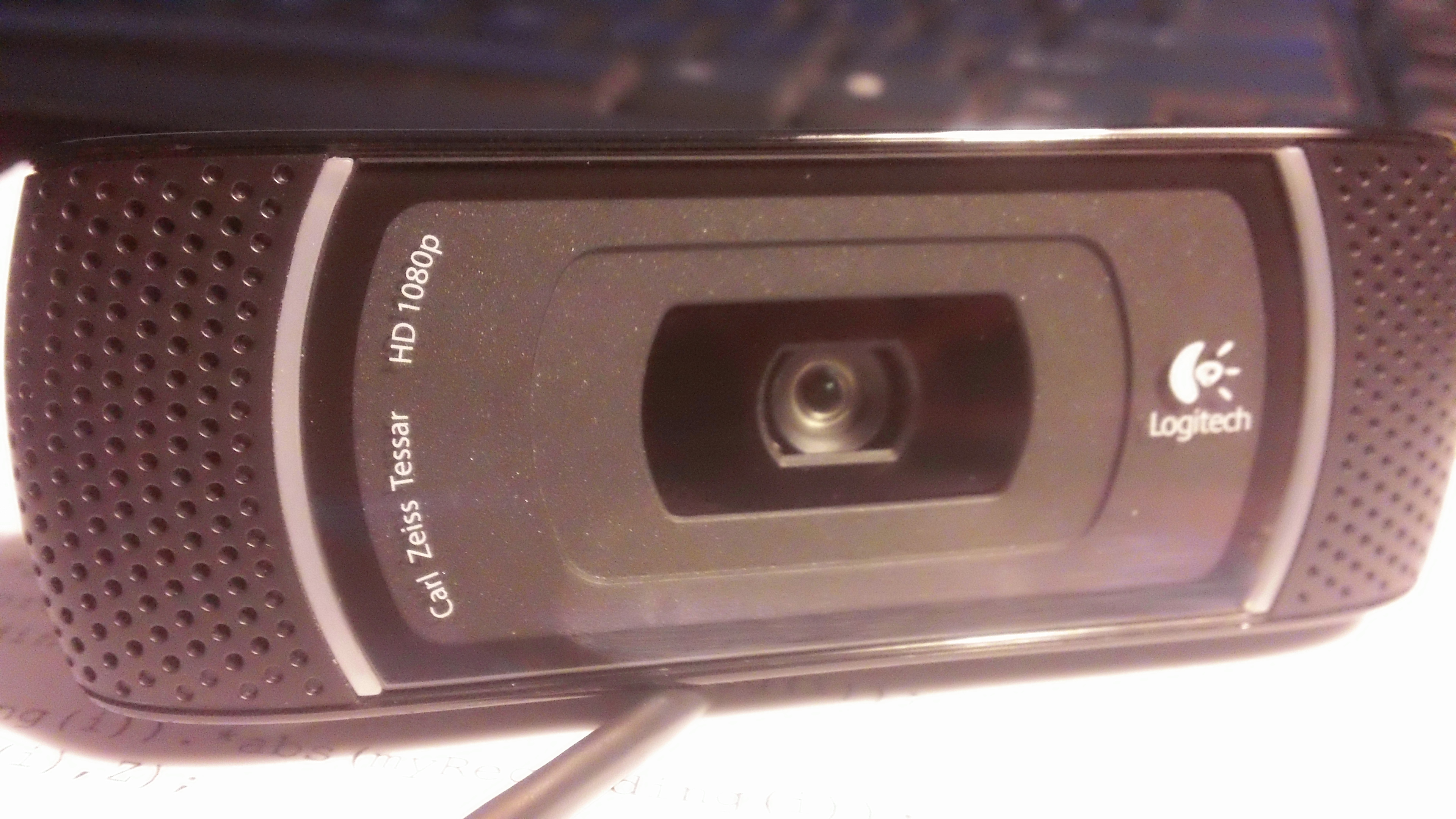
A microphone (or a webcam with a microphone feature)
The latest version of the MATLAB software
Setting Up the Code
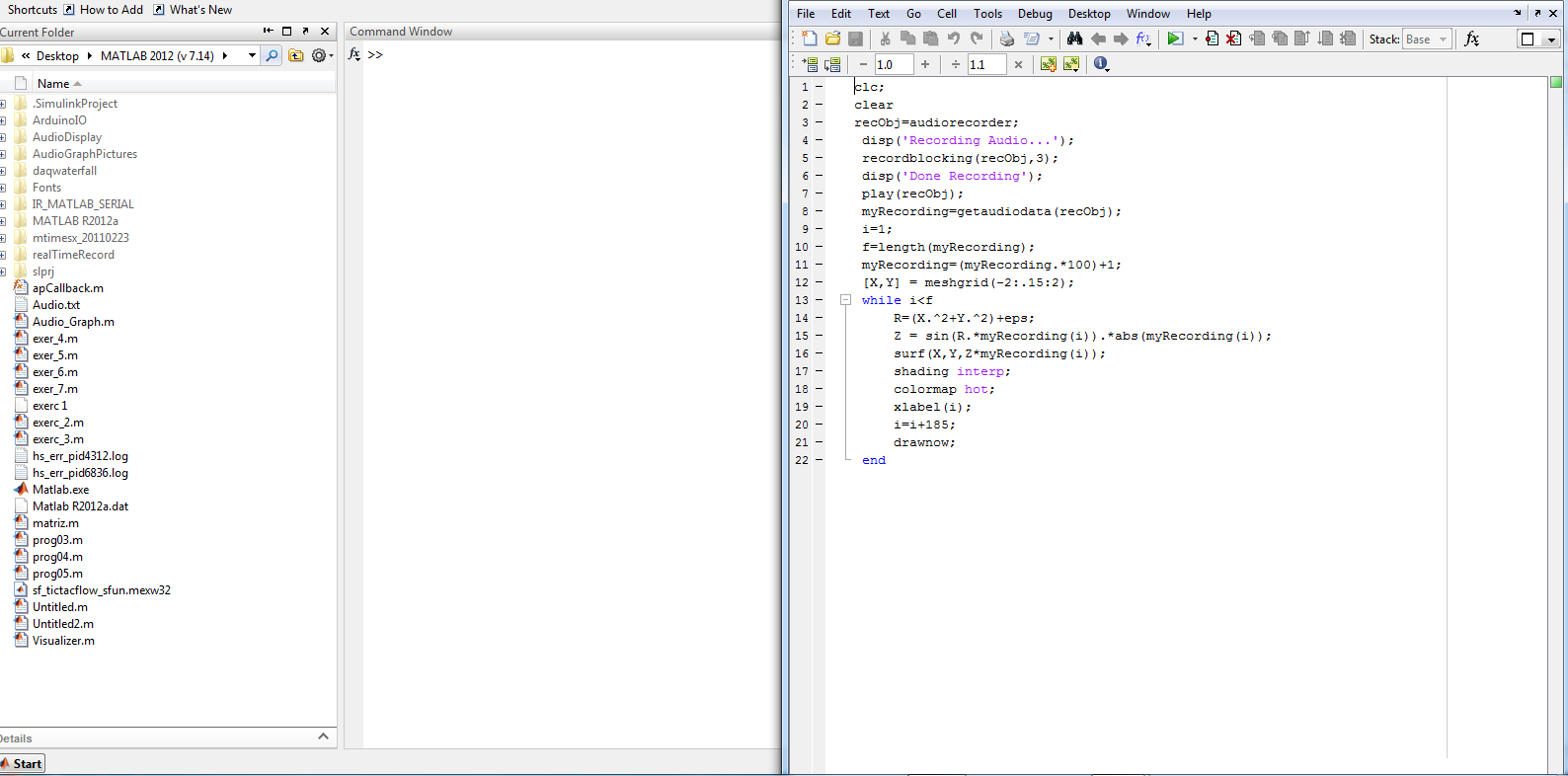
1. Open MATLAB and create a new script by pressing ctrl+N or by selecting File->New->Script.
2. Paste the following code into the window:
clc;
clear
recObj=audiorecorder;
disp('Recording Audio...');
recordblocking(recObj,3);
disp('Done Recording');
play(recObj);
myRecording=getaudiodata(recObj);
i=1;
f=length(myRecording);
myRecording=(myRecording.*100)+1;
[X,Y] = meshgrid(-2:.15:2);
while i R=(X.^2+Y.^2)+eps;
Z = sin(R.*myRecording(i)).*abs(myRecording(i));
surf(X,Y,Z*myRecording(i));
shading interp;
colormap hot;
xlabel(i);
i=i+185;
drawnow;
end
3. Select File->Save As... and name the file Audio_Graph.m
MATLAB Figure Setup


At this point you will test the program but keep in mind that we have not set up the code for your device so it will not be accurate.
Press F5 or click the green arrow button located at the top of the Editor window.
The console will now display the words "Recording Audio..." followed three seconds later by "Done Recording".
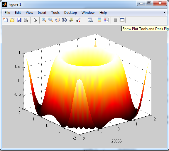
Once this has occurred the program will play the audio back and display a 'Figure' window with the rough Data Graph.
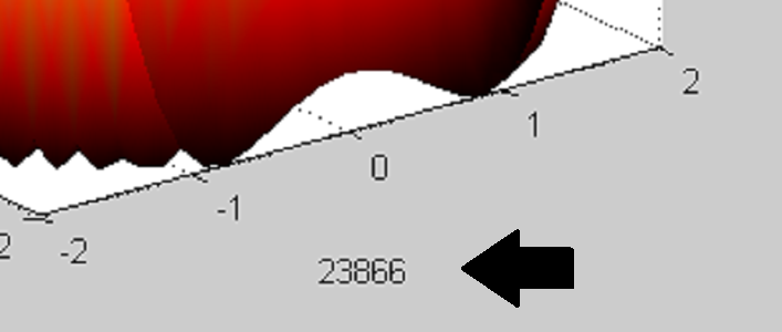
Once the graph reaches iteration 23866 as seen in the lower right corner of the Figure window the program has finished.
You must now do the following:
Click the 'Show Plot Tools and Dock Figure' button in the top right corner of the Figure window.
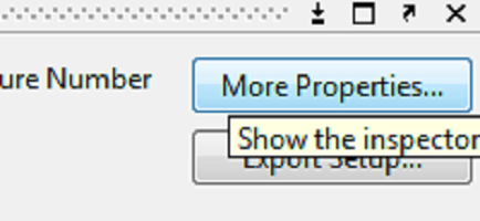
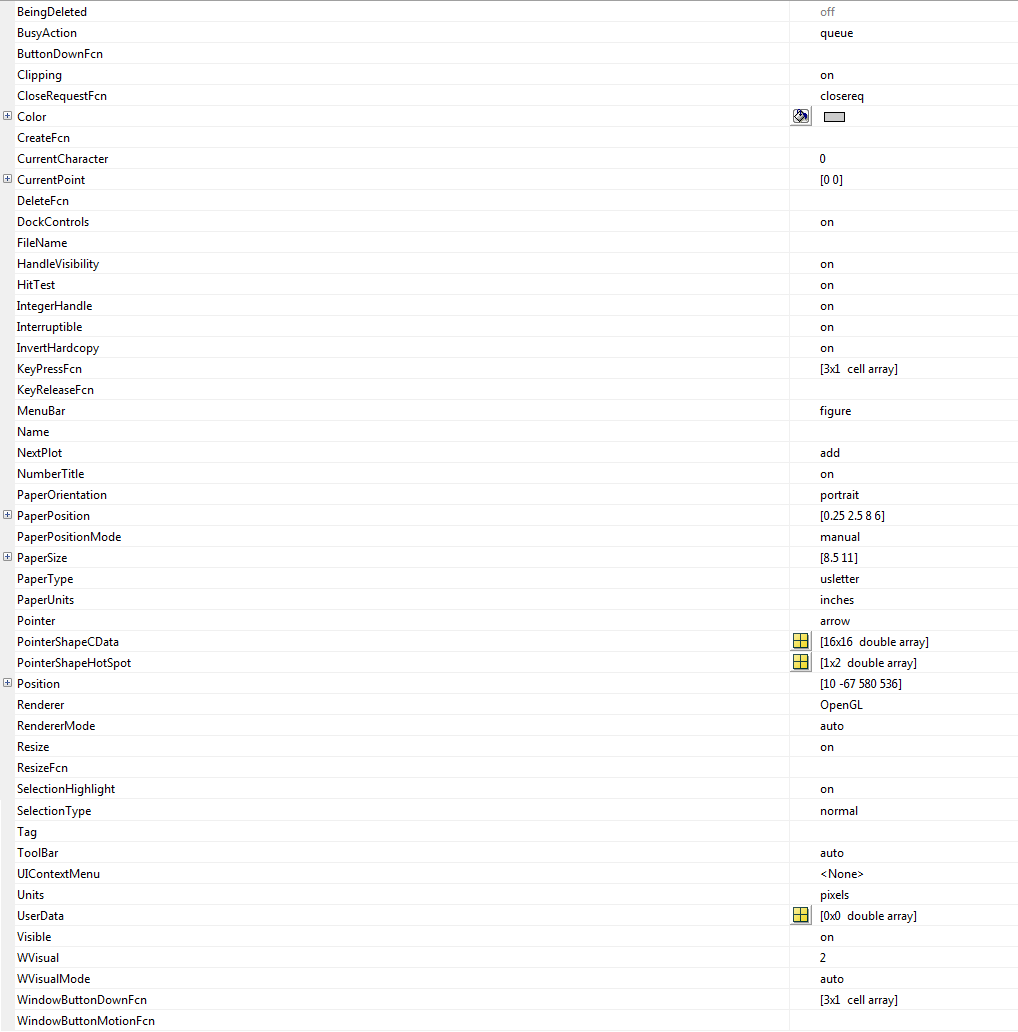
Click 'More Properties...' in the lower right corner.
Ensure that your data matches the data shown in the pictures for this step.
Configuring the Code for Your Device
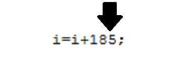

There are a few places you will need to manipulate the code for it to work the best on your device.
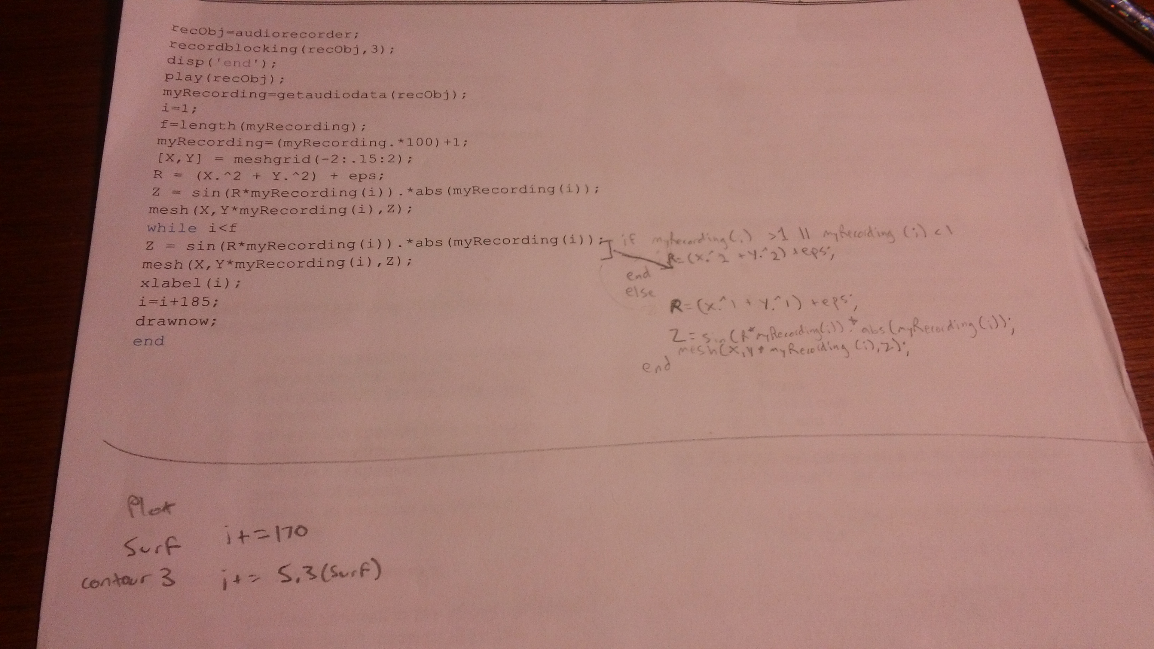
The first thing you will need to change is segment labeled 'recordblocking(recObj,3)' where the 3 is the seconds that the audio will be recorded for. You can change this value but try to keep it as an integer. Keep in mind that if you change this value again, you will need to repeat the next part of this step as well.
The next part to change is the segment 'i=i+185;'. The value of 185 will need to be changed depending on the speed of your device. The process for determining the correct value for this is as follows:
-Run the program in a quiet scenario and clap loudly in the middle of the audio clip. This creates a sharp data incline that should be easily visible on the graph.
-If the graph displays the change before the audio is heard through playback, decrease the number. If the graph is delayed in displaying the data change, increase the value. You can fine tune this as much as you like to obtain a more accurate program however you must keep the value as an integer. If you want the display to be slow so that you can examine the fluctuations of the graph you can remove the line 'play(recObj);' and change the 'i' value to 1.
More About the Code

This step is just a brief explanation of what the different aspects of the code do and why they are coded the way that they are.
When audio data is stored, the 'double' values appear as both positives and negatives, so in order to stop the graph from flipping upside down over and over we use the absolute value function *abs(myRecording(i)); so that the absolute value of the double value in index 'i' of double array 'myRecording' is kept positive. If you want to invert the graph but keep these properties you can multiply the absolute value of the index value by (-1).
In the while loop the loop counter 'i' is meant to be manipulated in order to sync the program with your computer speed.
The line 'shading interp;' refers to the shading type of the Figure being drawn and can also be changed.
The line 'colormap hsv;' is similar however it refers to the coloring sequence used to create the Figure being drawn and can be easily changed.
Finish and Continue
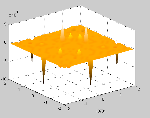
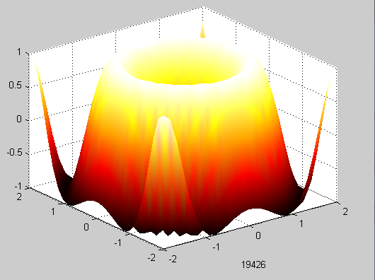
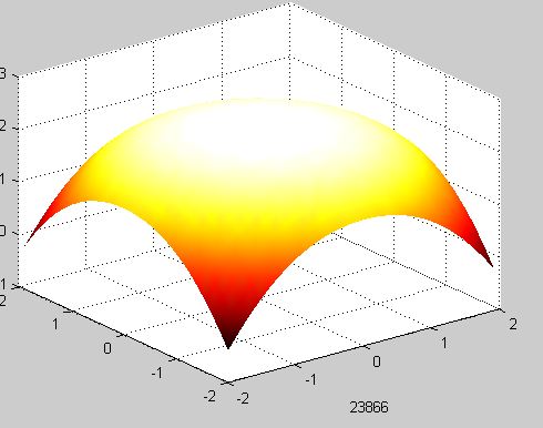
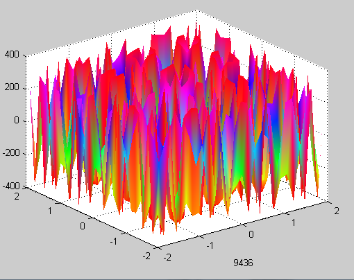
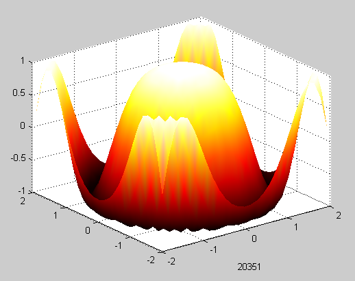

When you have completed the steps you can either keep the code you have altered or you can try to substitute some of the values and operations used with your own. Maybe a tangent graph could replace sine or maybe cosine... and what happens when you remove the absolute function? What would the graph look like if it was upside down (A hint on how to do that is in the previous step)? Maybe you can change the colors or textures and blending features? If you come up with any creative alterations post the code in the comments so others can see!
Happy Coding!