3 Bit Binary Adder

In this project, we will be creating a 3 by 3 bit binary multiplier using logic gates and arduino microcontroller. This circuit is able to multiply 2, 3 bit binary numbers together and display the output. The entire circuit on its own is about 30 total gates, 9 individual gates, 3 half adders and 3 full adders. This requires 8 chips to drive which does not fit on a standard breadboard. To work around this, this circuit has the full adders logic be performed by the arduino which takes 3 inputs and sends out 2 outputs per full adder. The output is displayed across 6 led's which represent the binary output (a 0 or a 1 depending on whether the led is on)
Supplies
Pre Logic Circuitry
.png)
Begin by placing adding all of our components onto the breadboard and setting them up with certain constants. The arduino will be functioning as a power supply for this circuit, connect the 5 volt and ground pins to the appropriate rails on the breadboard's power rails. Place both of your dip switches on the far left side of the board, then jump power into the rails where the first 3 switches of each dipswitch lies. Then jump ground to the opposite side of the power jumper using a 10k Ohm resistor. You can choose between making the power come from the top or the bottom and having the resistor be opposite, the input will be taken from the rail connected to the resistor. For my circuit, I alternated top and bottom with my switches in order to make most of the breadboard space. Now place your 5 chips, they can be placed in any order over the dip of the breadboard as close to the dipswitches as possible to conserve space. I'd recommend placing 3 ANDS, 1 XOR then 1 AND because it fits the flow of the circuitry. Jump power and ground into the appropriate legs for each of the chips, also connect the top and bottom power rails together using wires on the far right allowing both power rails to be functional. Finally, place your 6 leds next to each other and provide them with ground to their cathodes using 330 ohm resistors.
Initial AND Gates

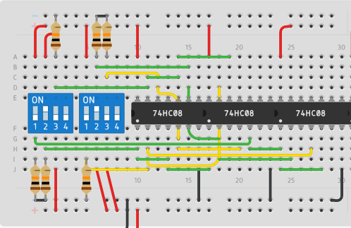
The first logic portion of this circuit involves every combination of every input being connected to their own AND gate. The entire list of required and gate connections is: A0B0, A0B1, A0B2, A1B0, A1B1, A1B2, A2B0, A2B1, A2B2. The only output for this step is A0 B0 directly to C0 as an output
Half Adders


After wiring the first 9 individual gates, we will wire the 3 half adders of the circuit. A half adder is comprised of 1 XOR gate and 1 AND gate with 2 inputs and 2 outputs, each of the 2 inputs connected to each of the gates. Outputs of A0B1 and A1B0 are the inputs of the first half adder, the XOR output is connected to led C1. A1B1 and A2B0 are the outputs of the second half adder. The rest of the outputs of the half adder will be wired during the full adder step.
Full Adders (arduino Wires)

As previously stated, the logic portion of the circuit related to the 3 full adders is controlled entirely through arduino meaning we connect pins for digital read and digital write purposes to our existing logic in order to simulate the logic of a physical full adder. Follow the connections as shown in the image above. The 3 full adders use a total of 13 pins meaning all digital pins expect 1 will be used for this step
Code
int a1 = 0;
int a2 = 1;
int a3 = 2;
int b1 = 3;
int b2 = 4;
int cin1 = 5;
int cin2 = 6;
int cin3 = 7;
int s1 = 8;
int s2 = 9;
int s3 = 10;
int cout1 = 11;
int cout3 = 12;
void setup()
{
for (int i = 0; i <= 8; ++ i) {
pinMode(i, INPUT);
}
for (int i = 9; i <= 14; ++ i) {
pinMode(i, OUTPUT);
}
}
void loop()
{
int ia1 = digitalRead(a1);
int ia2 = digitalRead(a2);
int ia3 = digitalRead(a3);
int ib1 = digitalRead(b1);
int ib2 = digitalRead(b2);
int icin1 = digitalRead(cin1);
int icin2 = digitalRead(cin2);
int icin3 = digitalRead(cin3);
int ib3 = ia2&ib2|ia2^ib2&icin2;
digitalWrite(s1,ia1^ib1^icin1);
digitalWrite(s2,ia2^ib2^icin2);
digitalWrite(s3,ia3^ib3^icin3);
digitalWrite(cout1,ia1&ib1|ia1^ib1&icin1);
digitalWrite(cout3,ia3&ib3|ia3^ib3&icin3);
}
After uploading this code to your arduino microcontroller ensuring you changed the pin numbers to ones that match your own, your 3 bit multiplier is complete.