$3 Alternative to Makey Makey
by arpruss in Circuits > Arduino
12475 Views, 41 Favorites, 0 Comments
$3 Alternative to Makey Makey
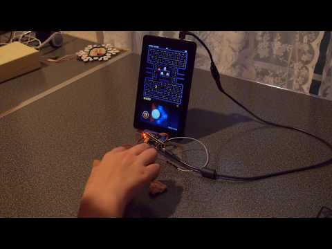
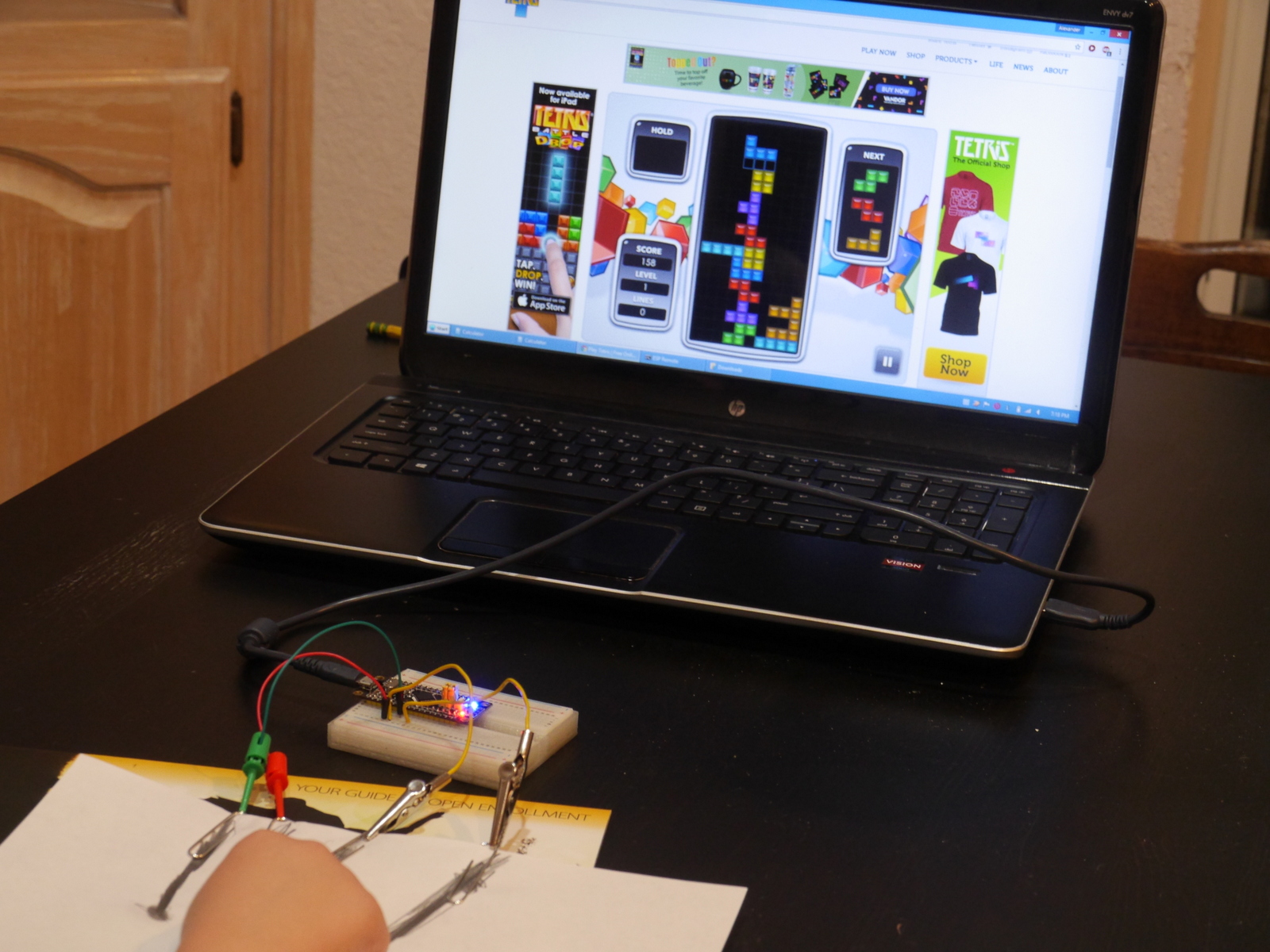
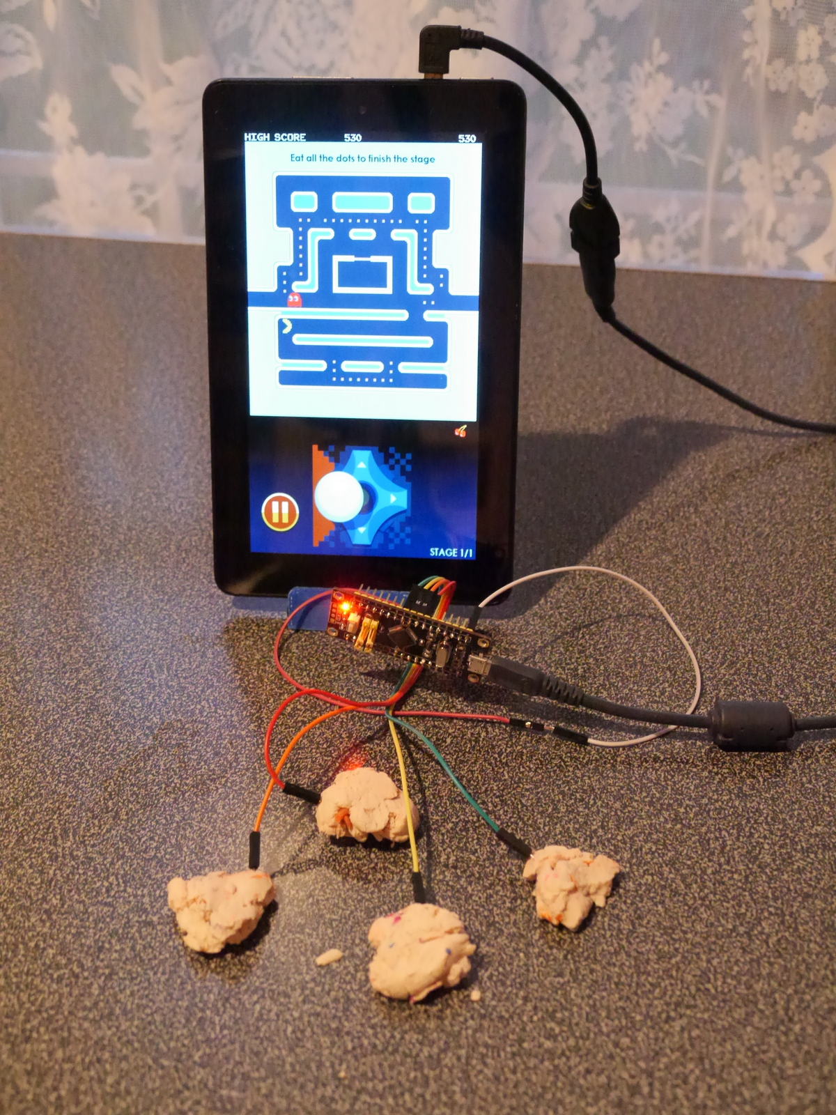
The Makey Makey is a great little device that emulates a USB keyboard and lets you make keys out of any somewhat conductive thing (aluminum foil, bananas, play dough, etc.), which can then be used as a controller for games and educational projects. The Makey Makey has two downsides: (1) cost and (2) the need for a ground connection.
This project is a cheap alternative using a $2 STM32F1 board and capacitive sensing. It only has 10 inputs as opposed to the Makey Makey's 12, but it has the advantage that in addition to emulating a keyboard, it can emulate a USB gamepad controller (digital joystick).
Parts:
- "black pill" STM32F103c8 board ($1.90 on Aliexpress; more information here)
- breadboard (less than $1 on Aliexpress) and jumper wires; or just a bunch female-to-male dupont connectors ($0.70 on Aliexpress for a pack of 40)
- paperclips, alligator clips, etc.
Tools:
- computer
- UART-to-USB adapter for initial board programming (an Arduino Uno or Mega will do the job, as will a cheap CH340 unit)
- soldering iron for soldering headers to board (you can also use a bunch of test clips without soldering, but they sometimes fall out)
The software is an example sketch included with my ADCTouchSensor library which allows for capacitive sensing with a single pin on the STM32F1 board per sensor (it's based on martin2250's library for AVR).
Warning: In dry weather, or where static is an issue (e.g., on a carpet), don't touch the exposed metal connectors lest you cause electrostatic damage to the STM32F1 board. I expect that the resistance of potatoes, bananas, play dough, etc. will help protect the board, but if you use bare aluminum foil, you might have problems. On the other hand, the board is only $1.90.
Educational activity ideas:
- Experiment to find out what items are conductive and can be used as control surfaces. (E.g., pencil lead vs. crayon; play dough vs. candle.)
- Write Scratch games that use a home-made controller.
- Modify the Arduino code powering the project to allow mouse click/movement, other keys, more than four joystick directions, etc.
Install Bootloader on Development Board
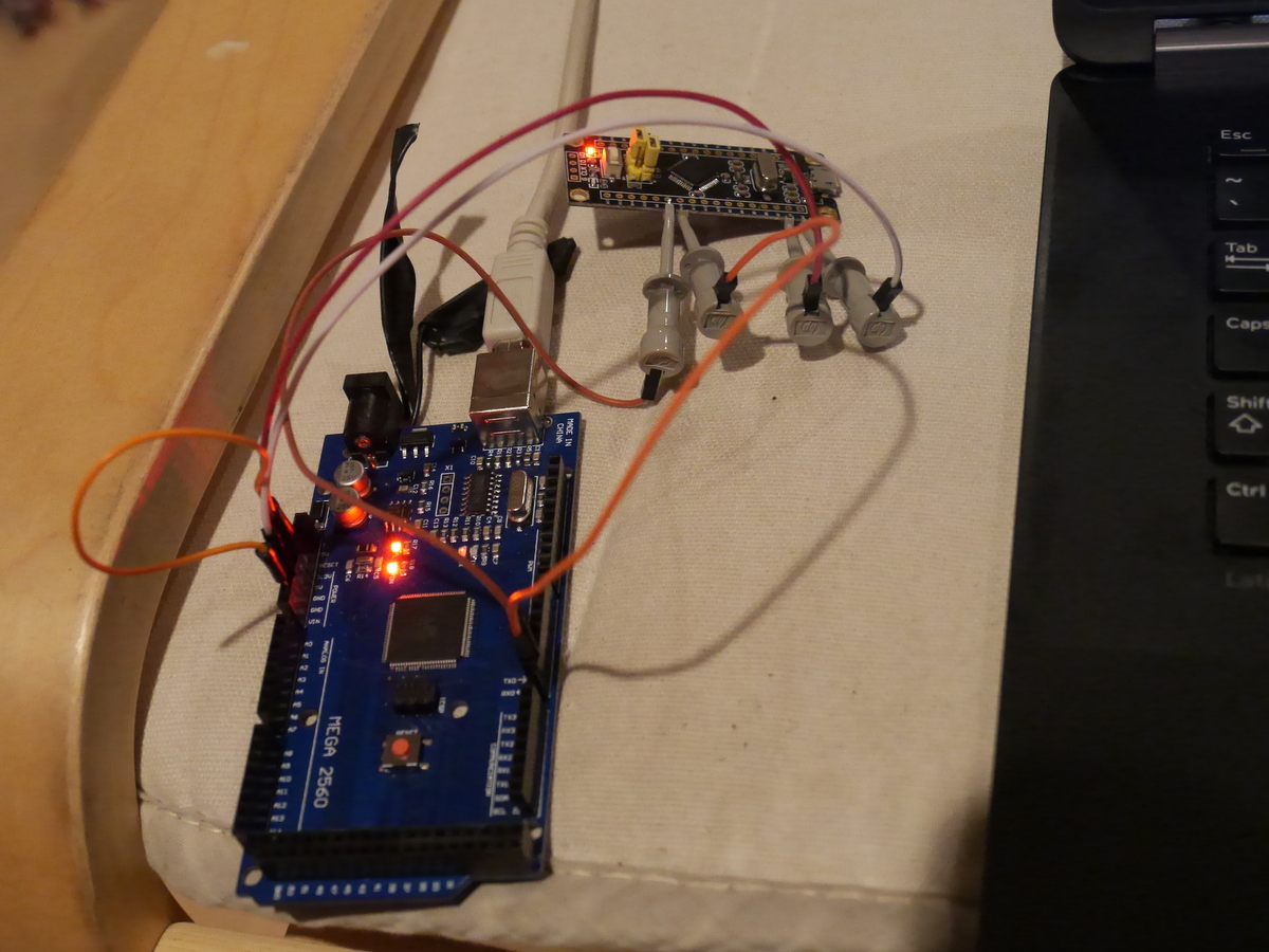
Solder the two three-pin headers in the middle of the Black Pill development system (B0-/center/B0+; B1-/center/B1+), and the long headers along the edges (if you're in a hurry, or want to avoid unnecessary pins that may confuse kids, you just need pins for A0-A10 and G).
You need a UART to USB bridge that is compatible with 3.3v devices. You can order a ch340 from Aliexpress for $0.66, but I had an Arduino Mega knockoff sitting around, and there was a cool trick I found online. If on an Arduino you short the reset pin to ground with a short wire, then it becomes a UART to USB bridge--no sketch needed. The only trick is that the RX and TX labeling becomes reversed: the Arduino's "RX" pin transmits and its "TX" pin receives. The Arduino runs at 5v and the Black Pill at 3.3v, but the PA9 and PA10 pins on the stm32f103 are 5V tolerant according, so that shouldn't be a problem.
On the headers you soldered, put a jumper from B0+ to center and from B1- to center.
Make the following connections:
- PA9 to UART bridge RX ("TX" if you're using the Arduino trick)
- PA10 to UART bridge TX ("RX" if you're using the Arduino trick)
- G to UART bridge ground
You can use a breadboard, or male-to-female jumpers, or if you want to do it before you solder the headers, you can use test clips (as in photo).
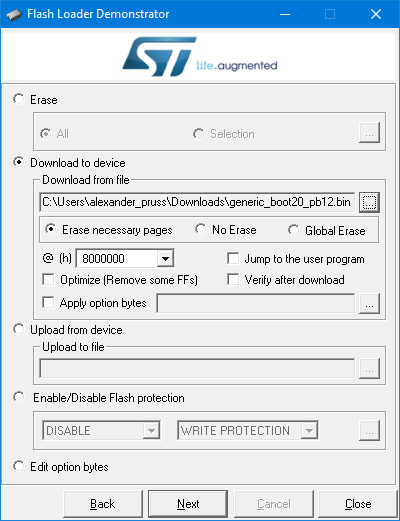
Download the bootloader binary. You want generic_boot20_pb12.bin.
On Windows, install ST's Flash Loader Demonstrator. On Linux (and maybe OS X and even Windows if you prefer commandline tools), use this python script instead, but my instructions will be for Windows. Connect your UART bridge to your computer.
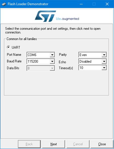
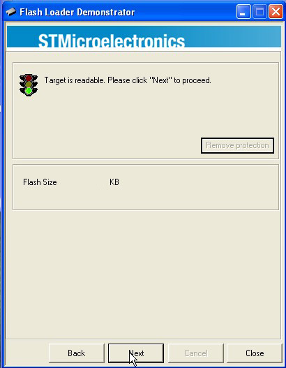
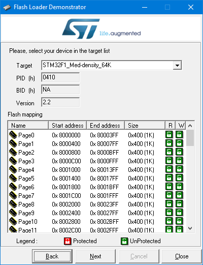
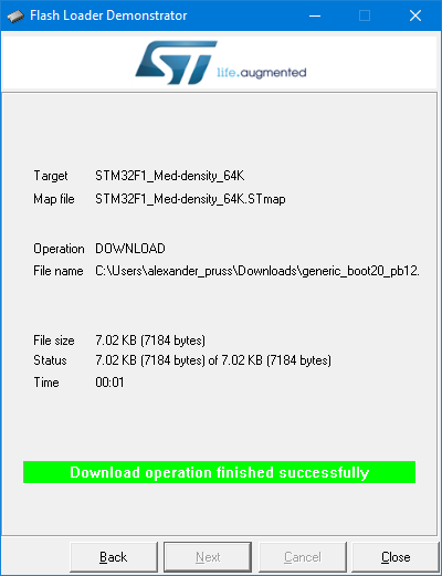
Power up the Black Pill via its USB port (if you use the computer, it will likely complain about an unrecognized USB device; ignore that). Start the Flash Loader Demonstrator. Choose the COM port for your UART bridge. Choose "Remove protection" if available. Choose a 64kb rather than 128kb flash version. And upload the bootloader binary.
Unpower everything and then move the jumper from B0+/center to B0-/center. You now have a bootloader that you can use with the Arduino IDE.
Set Up Arduino IDE
I assume you have the latest Arduino IDE installed.
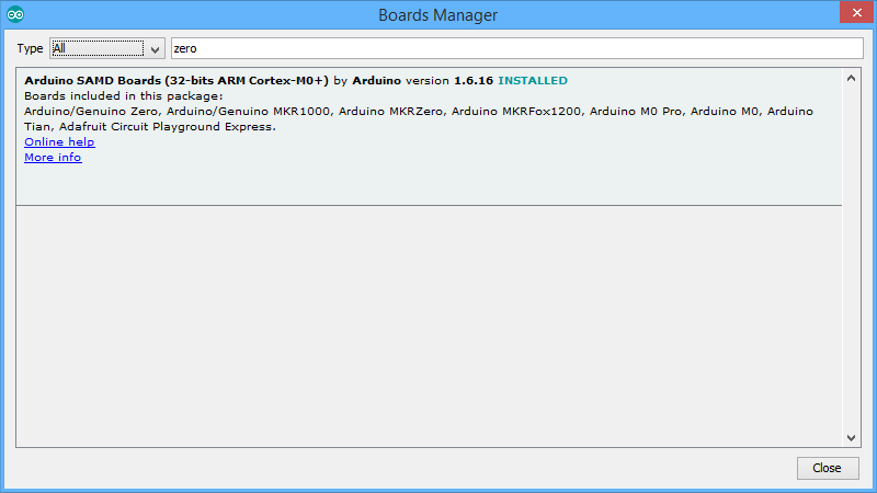
In Tools | Boards | Boards Manager, install support for the Arduino Zero (just put Zero in the search, click on the found entry, and then Install). Yes, you aren't working with a Zero, but this will install the right gcc compiler.
Next, download the stm32duino core. On Windows, I recommend downloading the zip file, since when I checked out the files (admittedly, with svn), I had some permissions problems with files in the Windows tools directory that needed fixing. Put the branch in Arduino/Hardware/Arduino_STM32 (so you'll have folders like Arduino/Hardware/Arduino_STM32/STM32F1, etc.) On Windows, install drivers by running drivers\win\install_drivers.bat.
Install CapacitiveController Sketch
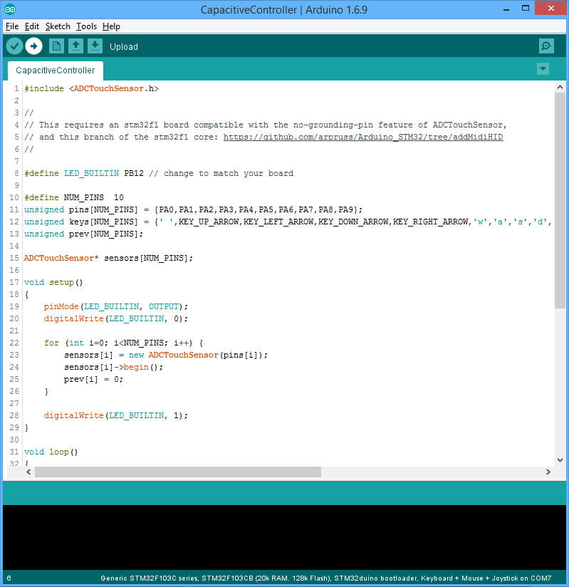
In Arduino IDE, choose Sketch | Include Library | Manage Libraries. Search for "ADCTouchSensor" and install version 0.0.6 or newer. Repeat and search for "USBHID" and install my USBHID_stm32f1 library.
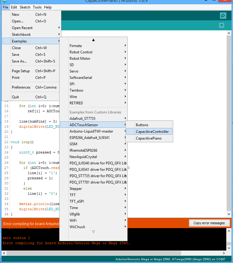
Choose File | Example | ADCTouchSensor | CapacitiveController.
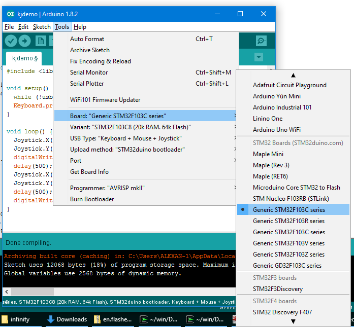
Make sure you have the following settings under Tools:
- Board: Generic STM32F103C8
- Upload method: STM32duino Bootloader
Plug the board into the computer and click the right-arrow "upload" button. You may need to reset the board (press the reset button on it) once the upload message shows up in the console.
Connections and Buttons
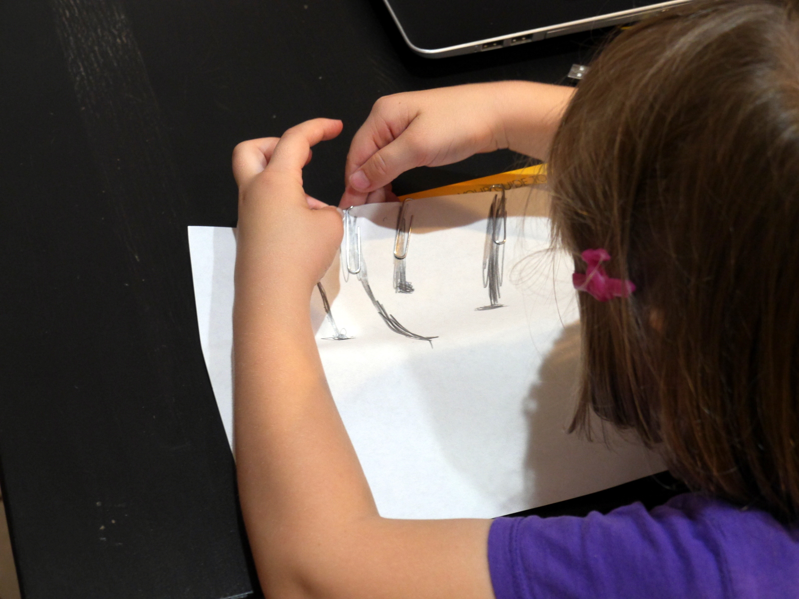
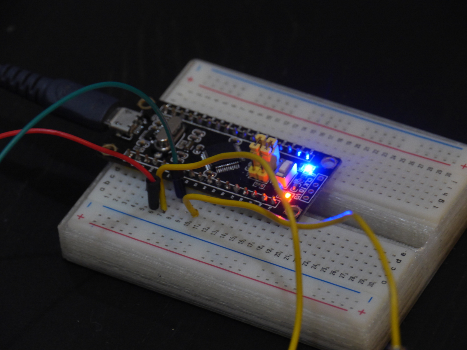

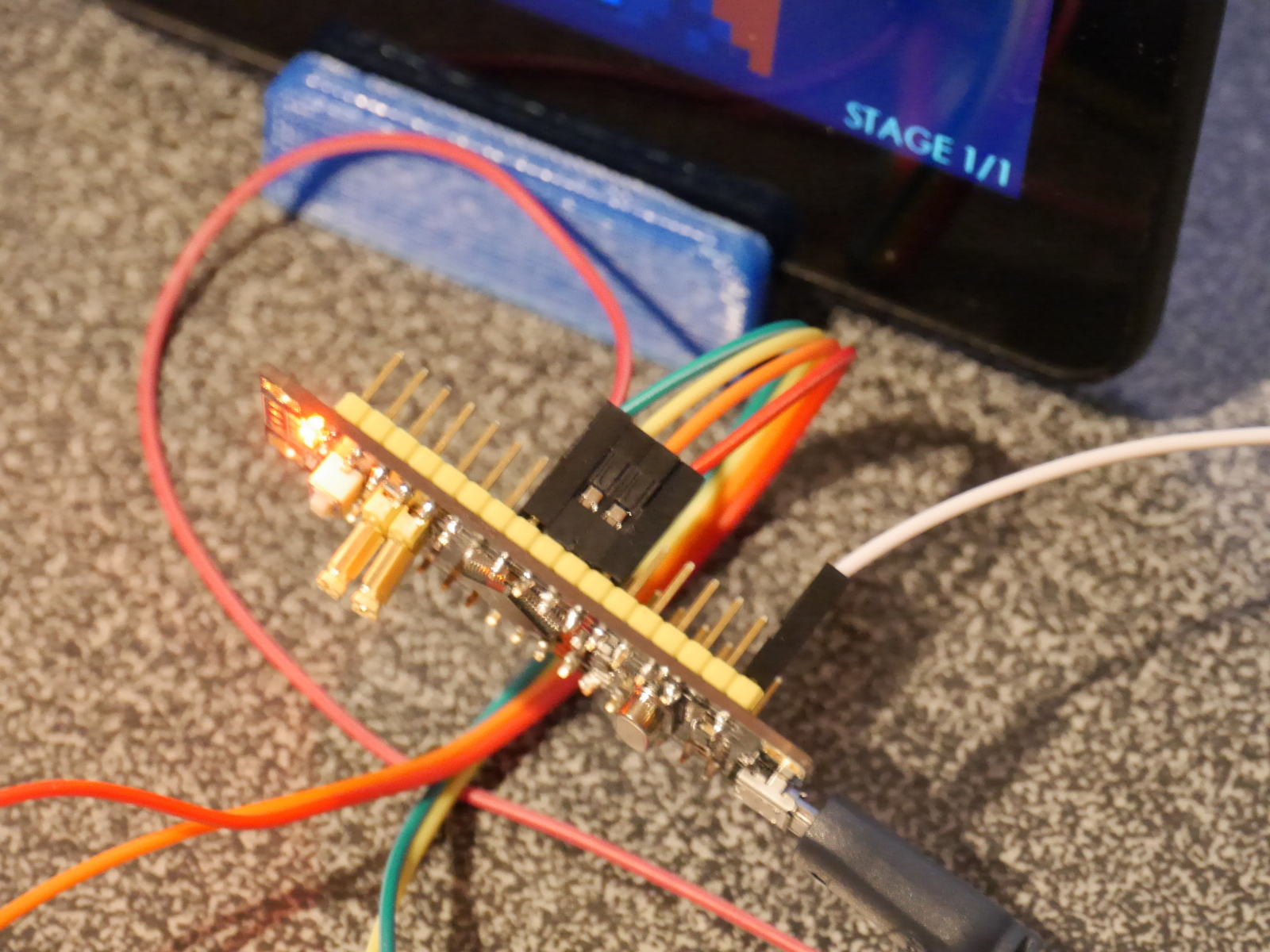
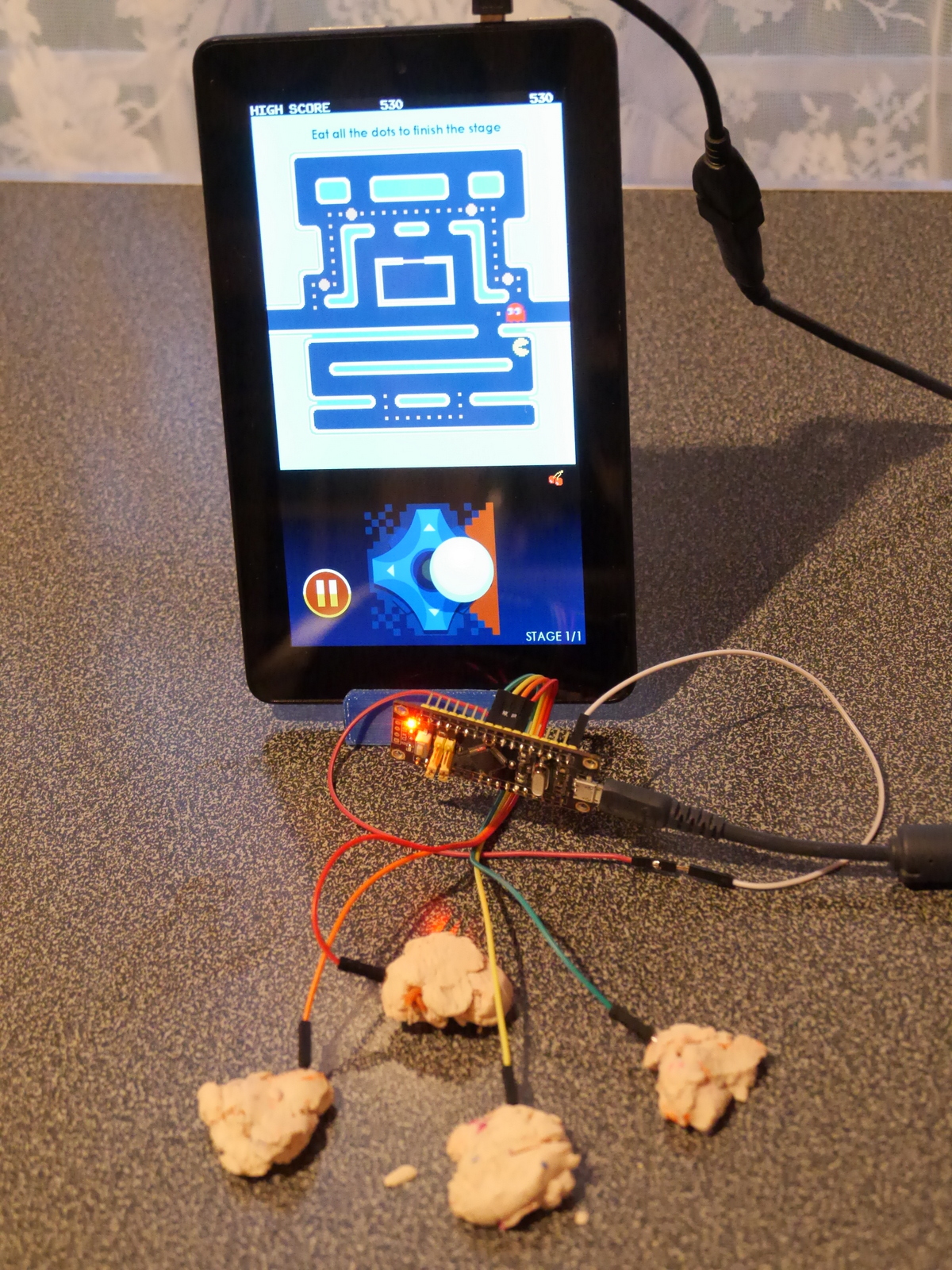
With the device unplugged, run wires from the STM32F1 pins to your control surfaces. Connect with alligator clips, paperclips, or just by sticking jumpers into objects. You can use a breadboard or female-to-male jumpers. For Tetris on the computer, we used keyboard mode and the arrow keys; for Pac Man on the tablet, we used a USB OTG cable and joystick mode.
The CapacitiveController sketch calibrates the capacitive sensors when it's turned on. Make sure that while you're turning it on, you aren't touching the control surfaces, wires to them or pins. And if you modify any control surface, you need to re-calibrate by unplugging and plugging back in or pressing the white reset button on the board.
Most of the apps here will work, as well as many others. You can also see how many Makey Makey projects you can adapt.
Some good control surfaces:
- fruits and vegetables
- play dough
- aluminum foil (except in high static conditions)
- heavily penciled buttons/connections on paper (the connection lines shouldn't be too long--in the photo, the bottom-most button didn't work)
- experiment with many more! (you can also try to tweak the 25 in if (sensors[i]->read() > 25) line in the source code for some surfaces)
Keyboard mode connections:
- Leave A10 disconnected
- A0: space
- A1: up
- A2: left
- A3: down
- A4: right
- A5: w
- A6: a
- A7: s
- B0: d
- B1: f
Gamepad/Joystick mode connections:
- Connect A10 to Ground (G) to set joystick mode
- A0: button 1
- A1: up
- A2: left
- A3: down
- A4: right
- A5-A7,B0,B1: buttons 2-6
Hint:
If you are using male-to-female jumpers, you can do the joystick mode A10-ground connection by jamming the male ends of two jumpers into each other, thereby forming a female-to-female jumper.