2:5 Scale KENBAK-1 Personal Computer Reproduction
by megardi in Circuits > Wireless
10074 Views, 63 Favorites, 0 Comments
2:5 Scale KENBAK-1 Personal Computer Reproduction


Background
If you are a fan of retro computers like I am, there's a good chance you will have seen on numerous occasions the KENBAK-1, regarded by many as the first commercial personal computer. Ten years ago Mark Wilson introduced KENBAK-uino, a reproduction running in emulation on an ATmega328. In 2016 Brian Benchoff posted a great writeup about John Blankenbaker KENBAK-1's creator. For a first hand account of the KENBAK-1 story you should really have a look at John Blakenbaker's own KENBAK-1 Computer site.
For a while you could purchase a full size KENBAK-1 Reproduction Kit, with a PCB, power supply, authentic metal case, 132 standard series TTL logic ICs as the CPU / process control logic (that's right no microprocessor) and two 1024 bit shift registers for memory. Unfortunately this option is no longer available, but based on Mark Wilson's code Adwater & Stir offers a ruler sized nanoKENBAK-1, a half size µKENBAK-1 kit, and will soon be offering a full sized kit as well. In addition you can find KENBAK-1 emulators online like this one.
Motivation
So with all of this rightly deserved KENBAK-1 love out there, why am I creating yet another KENBAK-1 reproduction? The flip answer might be that I want to and I can, but that's not all of it. While all of the wonderful reproductions out there emulate the original to a tee and give a true KENBAK-1 experience, and even have some addition features like built in programs, at the end of the day you are still in many cases hand translating machine instructions and keying them in via the front panel buttons one step at a time. And when something goes wrong, while you can step through your program one instruction at a time you only have visibility into one thing at a time on the front panel display, the instruction or a memory/register address. It gets old pretty fast.
Where I think I can add some value is to integrate the machine code Emulator with an Assembler and a Debugger. You will still be able to fire up my KENBAK-2/5 console to key and run your programs in native mode via the front panel. In addition you will be able to open an integrated development environment, enter in a KENBAK-1 program via assembly language and run said program using the actual console. Similarly you will be able to step through your assembly code, set break points, and observe memory and register contents as you do.
My other motivation for this project is that I really wanted to do a deep dive on this machine. When I looked at the Programming Reference Manual I was very impressed with the machine architecture and the instruction set. I mean an Indirect Indexed addressing mode on a machine built with logic chips. So cool.
Design Considerations
The console itself will be rendered at 2:5 scale (hence the name KENBAK-2/5). This is primarily so that all of the parts will fit onto the print bed of my Prusa MK3S. A built in Raspberry Pi 4 will be connected to the front panel via a 32 channel port expander. In addition to running the KENBAK-1 Emulator, the extra horse power of the Pi will be required to run the "integrated development environment" (IDE). The IDE can be accessed by connecting a display, keyboard, and mouse to the console's Pi 4 itself or via VNC (preferred). The Emulator, Assembler, and Debugger will be written in Python.
Supplies
In addition to the 3D printed parts you will require the following:
- 1 Raspberry Pi 4
- 1 MCP23017 32 Channel I/O Expansion HAT (https://www.buyapi.ca/product/mcp23017-hat-32-channel-io-expansion-hat/)
- 12 3mm LEDs (8 white and 4 yellow)
- 2 Toggle switches (KINYOOO SPDT Mini Toggle, On/On 3 Pins 2 Position - Amazon)
- 15 Push Button Switches (Mini 7mm Momentary (Off-ON) Push Button - Amazon - 8 black and 7 white)
- Hook up wire. I used 22 AWG.
- Female headers with 2.54 mm spacing.
Print the Parts
I printed the parts with no supports and the following settings (unless other wise specified):
Print Resolution: .2 mm
Infill: 20%
Filament: AMZ3D PLA Colors: I used grey and lake blue to be consistent with the original. Your call.
Notes: Print the parts in their default orientation.
To make a KENBAK-2/5 you will need to print the following parts:
- 1 - Body Bottom
- 1 - Body Top
- 1 - Front Panel
- 2 - Side Clamp
Assemble the Console
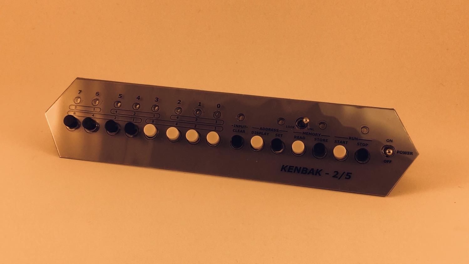
The KENBAL-2/5 console has a 3D printed frame and uses panel mount components. At 40% the size of the original a few compromises had to be made. For one, the great keyboard style push buttons on the front panel of John Blankenbaker's machine proved impossible to replicate. In fact the button positions had to be stretched out horizontally a bit on my reproduction to accommodate the small panel mount push buttons that I did find. Similarly no nice sockets for the panel lamps, just rear mounted 3 mm LEDs.
The advantage of the small size is that the pieces will fit on a fairly large selection of 3D printers out there. The shape of the case is a pretty close match to the original as far as I can tell. It is printed in five parts. The bottom has mounting pegs for this project's Raspberry Pi "engine" and cutouts for cabling.

Nothing special about top piece. Notice the groove in both the top and bottom pieces used to hold the front panel in place.

The front panel has holes to hold the buttons, switches, and lights. Because of the small size of the reproduction I was not able to just 3D print the labels directly on the panel as I have in the past with other projects. Instead I saved a DXF file with the panel outline and hole positions from my Fusion 360 model and brought that into Inkscape where I added the labels. I printed the resulting SVG file onto a clear acetate sheet which I laminated to protect the printing and add rigidity to the overlay. I cut the overlay out along the outline and punched the button and switch holes with a standard hand held 1/4" paper punch. The panel lights are recessed behind the overlay so do not require holes.

I could not use the nuts that came with the panel mount buttons and switches because they would not fit at this scale. Instead I sized the holes in the front panel so that the components could be screwed in from the back self threading as they did. The LEDs are just friction fit.

The overlay with the labels will just fit over the buttons and switches with a little finessing.
The front panel fits into the grooves cut into the top and bottom pieces.

Join the top and bottom pieces with the slotted side pieces.

And that's it for the console.

Downloads
Wire the Console

The front panel lights, buttons, and switches are connected to the Raspberry Pi through the Port Extender pictured above. The port extender came with standoffs, so I used two diagonal corner holes on the Raspberry Pi to mount it to the bottom frame, and the opposite two corner holes with the standoffs to support the hat. Seems reasonably solid.
The wiring is as follows with the pin numbers mapping to front panel components:
IC1
- Stop Lamp
- Store Lamp
- Set Lamp
- Clear Lamp
- Toggle Off
- Toggle On
- Toggle Unlock
- Toggle Lock
- Data Lamp 0
- Data Lamp 1
- Data Lamp 2
- Data Lamp 3
- Data Lamp 4
- Data Lamp 5
- Data Lamp 6
- Data Lamp 7
IC2
- Stop Button
- Start Button
- Store Button
- Read Button
- Set Button
- Display Button
- Clear Button
- n/a
- Data Button 0
- Data Button 1
- Data Button 2
- Data Button 3
- Data Button 4
- Data Button 5
- Data Button 6
- Data Button 7
In the following photo I'm about half done. A ground wire has been routed to all of the front panel components, the fifteen push buttons have been connected to the hat, and the twelve LEDs have a short wire with a limiting resistor attached. The resistors are 10k to keep the brightness down.

I used female headers to connect the front panel lights and buttons to the extender. Because there wasn't a lot of head room with the top frame on, and limited space between the male headers on the board, I had to angle the wires as in the photo below.

It was a little tight, and as I soldered the wires onto the the header I kept asking myself why I hadn't designed a PCB for the front panel. At the end of the day though it worked out OK.

The red heat shrink protects the "inline" limiting resistors for the LEDs. The front panel components ground wire is attached to the Raspberry Pi ground pin (black wire). A few cable ties and my KENBAK-2/5 hardware is ready to go.
About the KENBAK-2/5 IDE

The IDE is written in Python and runs on the Raspberry Pi at the heart of the KENBAK-2/5 hardware. It consists of four major components:
- Console - Allows the Raspberry Pi to interact with the front panel switches, buttons, and lights through the port extender.
- Emulator - Simulates in software the operation of the 134 integrated circuits that made up the original KENBAK-1's hardware. It accepts as input a 256 byte array that represents the entire block of memory that was in a KENBAK-1 and executes the instructions encoded into those bytes until a HALT instruction is encountered or the user presses the Stop button.
- Assembler - Takes a symbolic representation of KENBAK-1 instructions, as defined in the Symbolic Representation of Instructions section of the Programming Reference Manual, and converts them into machine code that can be executed by the Emulator (or an original KENBAK-1 if you are lucky enough to have access to one).
- Debugger - Allows the user to set breakpoints in their code that will stop execution at that point so that the machines memory and registers can be viewed.
Looking at the image above you can see that I have just loaded a Fibonacci Sequence calculator program written in KENBAK-1 assembly language. The upper right quadrant is of course the assembler code and to it's left the equivalent binary instructions. By clicking on the binary instructions you can set or clear breakpoints (the skp instruction has a breakpoint set for instance).
To the lower left is the state of the predefined "registers" including the address register which is used to load and read memory locations. In the KENBAK-1 architecture registers as just predefined memory locations. The values of nine special memory locations in the KENBAK-1:
| Name | Address | Usage |
|---|---|---|
| A | 000 | A register. |
| B | 001 | B register. |
| X | 002 | X register. |
| PC | 003 | Program counter. |
| OUTPUT | 128 | Maps to front panel data display lamps. |
| OCA | 129 | Overflow/Carry bits for A register. |
| OCB | 130 | Overflow/Carry bits for B register. |
| OCX | 131 | Overflow/Carry bits for C register. |
| INPUT | 255 | Maps to the front panel data input button |
Middle bottom is a hex dump of all 256 memory locations, and lower right shows the same memory locations in more detail with hex, decimal, octal and binary representations for each location. All references to memory locations are in decimal (leftmost columns in the instruction, hex dump, and details panels and rightmost column in the instruction panel).
The entries rendered in green represent the memory location currently pointed to by the program counter (PC).
The front panel console is fully integrated with the IDE. So for instance you could start the Fibonacci program shown above by pressing the physical START button on the console or by clicking the Run button in the IDE. Similarly pressing and holding the STOP button and then pressing START will perform a single step as will the IDE's Step button.
Anything written to the OUTPUT register will show up on the data lamps on the console. Data stored from the console to memory locations through the address register will be reflected in the IDE.
The IDE does offer some additional features. Your programs can be saved and loaded to disk (the assembler code and the binary memory image both). The Restart button will reset everything to the last loaded image. Clear will zero out memory and the assembler program space then set the PC to memory location 4. Auto will run the program at a rate of about one instruction per second.
You can debug your program by single stepping or by setting breakpoints and observing the memory and registers.
If you just want to play around with KENBAK-1 code, you can run the IDE "standalone" on any platform that supports Python, but of course you will only be able to integrate the KENBAK-2/5 console on a Raspberry Pi since it's bound to the wiringpi library.
Install the Software
The KENBAK-IDE.py file is available from my GitHub repository. If used outside of the KENBAK-2/5 hardware environment, it should run on any machine that supports Python3 without any library dependencies. In this mode you can still write, debug, and run KENBAK-1 assembly language programs. It's a great learning environment all by itself.
If you are running on the KENBAK-2/5's Raspberry Pi with the port extender hat you will have to first make sure that the wiringpi library is installed.
pip3 install wiringpi
I created a folder on the Pi
mkdir /home/pi/KENBAK-1
and copied the KENBAK-IDE.py, Assembler Syntax.txt, Fibonacci.asm, and Fibonacci.bin files there. Then its a simple matter of running the Python script.
cd /home/pi/KENBAK-1
python3 KENBAK-IDE.py
Auto Start the KENBAK-2/5 IDE
If you are running KENBAK-1 IDE as a dedicated console on the built-in Raspberry Pi like I am it's convenient to have the program start automatically when the machine boots. Here is what I did to make this happen.
I created an autostart folder on my Pi and switched to that folder.
mkdir /home/pi/.config/autostart
cd /home/pi/.config/autostart
Into the autostart folder just created I added the following two files.
runKENBAK-1
cd /home/pi/KENBAK-1
/usr/bin/python3 KENBAK-IDE.py
KENBAK-1.desktop
[Desktop Entry]
Type=Application Name=KENBAK-1
Exec=/home/pi/.config/autostart/runKENBAK-1
In addition the runKENBAK-1 file must be made executable with the following command:
chmod 777 runKENBAK-1
Now if you reboot the system, you should briefly see the desktop appear, and shortly after KENBAK-IDE application will load.
Setting up VNC
Current Raspberry Pi OS versions have RealVNC baked in. If you are running the Raspberry Pi in the KENBAK-2/5 console headless as I am you have to setup a virtual desktop for the VNC client to connect to. The easiest way I have found to do this is to add the following lines to the end of the /etc/rc.local file before the exit 0 on the Pi.
# Setup a virtual screen for the VNC server.
sudo -u pi vncserver -randr=1920x1080
Set the screen dimension to be the same as the machine that you will be accessing the KENBAK-IDE from. You should then be able to connect to the KENBAK-2/5 with a RealVNC client at the console machine's IP address with a :1 appended, for example in my case 192.168.123.122:1.
Finishing Up

As pictured above I added a Help button to popup some information on the Assembly Language Syntax.
I made a video where I try to demonstrate how the KENBAK-2/5, with it's built in Raspberry Pi, does a good job as a KENBAK-1 reproduction. As with the original you can enter and run programs, and view internal machine memory, just using the switches, buttons, and lamps on the front panel of the console.
But in addition, using the power of the Raspberry Pi 4 to implement an Integrated Development Environment, you can key in programs using native KENBAK-1 assembly language. As can be seen in the video, the Assembler has no "passes". The assembler instructions are continuously parsed as you type and when the corresponding binary code no longer has any question marks you know the syntax for the line is correct. It seems works quite well.
With breakpoints, single step modes, and memory visualizations, debugging suddenly becomes a lot easier.
When I first looked at the KENBAK-1 Programming Reference Manual I was very impressed with the instruction set for a machine with no microprocessor, just discrete logic chips. Implementing an Assembler and Emulator only served to deepen my appreciation for what John Blankenbaker created. It was quite an achievement for its time and John Blankenbaker deserves his place in history as an early personal computer pioneer.
One More Thing
When John Blankenbaker was demonstrating his KENBAK-1 Personal Computer back in 1971, one of the programs he always showed was a Day of the Week calculator. Given any date, it can tell you what day of the week that date fell on. It was something that was pretty cool that everyone could relate to.
Well I didn't feel that my KENBAK-2/5 reproduction would be quite complete until it could do the same. It was a fun programming challenge that exercised a lot more of the capabilities of my machine, and in fact uncovered a few minor issues with my emulator software:
- JMK operand was not saving the return address correctly
- HALT operand needed to advance the program counter (PC)
- I tweaked some of the console interactions.
- I added a DB directive to reserve a byte of memory.
I feel a lot more confident now that my reproduction is a very close work-a-like to the original. Here is the code:
; Program to calculate the day of the week for any date. To start this program you will
; have to input the date in four parts: Century, Year, Month, and Day. Each of the parts
; is entered as a two digit Binary Coded Decimal number (ie. the first digit will occupy
; bits 7-4 as a binary number, and the second digit bits 3-0) using the front panel data
; buttons. The steps to run this program are:
;
; 1) Set the PC register (at address 3) to 4.
; 2) Clear the input data then enter the date Century.
; 3) Press Start.
; 4) Clear the input data then enter the date Year.
; 5) Press Start.
; 6) Clear the input data then enter the date Month.
; 7) Press Start.
; 8) Clear the input data then enter the date Day.
; 9) Press Start.
;
; The day of the week will be returned via the data lamps using the following encoding:
;
;      7-Sunday 6-Monday 5-Tuesday 4-Wednesday 3-Thursday 2-Friday 1-Saturday
;
; All lamps turned on means the last item entered was invalid and you have to restart.
;
;
; Get the date we want the day for.
;
    	load    A,INPUT            	; Get the century.
    	jmk     bcd2bin
    	store   A,century
    	halt
    	load    A,INPUT            	; Get the year.
    	jmk     bcd2bin
    	store   A,year
    	halt
    	load    A,INPUT            	; Get the month.
    	jmk     bcd2bin
    	sub     A,1            		; Convert from 1 based to 0 based.
    	store   A,month
    	halt
    	load    A,INPUT            	; Get the day.
    	jmk     bcd2bin
    	store   A,day
    	load    A,0b10000000        	; Setup the rotation pattern.
    	store   A,rotate
;
; All the inputs should be in place. Start the conversion.
;
    	load    A,year           	; Get the year.
    	sft     A,R,2           	; Divide by 4.
    	store   A,B            		; Save to B the working result.
    	add     B,day            	; Add the day of the month.
    	load    X,month            	; Use X as index into the month keys.
    	add     B,monkeys+X        	; Add the month key.
    	jmk     leapyr            	; Returns a leap year offset in A if applicable.
    	jmk     working            	; Working...
    	sub     B,A            		; Subtract the leap year offset.
    	jmk     cencode            	; Returns a century code in A if applicable.
    	jmk     working            	; Working...
    	add     B,A            		; Add the century code.
    	add     B,Year            	; Add the year input to the working result.
chkrem  load    A,B           		; Find the remainder when B is divided by 7.
    	and    A,0b11111000        	; Is B > 7?
    	jmp    A,EQ,isseven        	; No then B is 7 or less.
    	sub    B,7            		; Yes then reduce B by 7.
    	jmk    working            	; Working...
    	jmp    chkrem            	; Check again for remainder.
isseven load   A,B        		; Is B = 7?
    	sub    A,7            		; Subtract 7 from B value.
    	jmp    A,LT,gotday        	; No B is less than 7.
    	load   B,0            		; Set B to zero because evenly divisible.
gotday  load   X,B           		; B holds the resulting day number.    Use as index.
    	load   A,sat+X            	; Convert to a day lamp.
    	store  A,OUTPUT
    	halt
error   load   A,0xff       		; Exit with error
    	store  A,OUTPUT        		; All lamps lit.
    	halt

;
; Store inputs.
;
century db
year    db
month   db
day     db
;
; Static table to hold month keys.
;
monkeys 1
    	4
    	4
    	0
    	2
    	5
    	0
    	3
    	6
    	1
    	4
    	6

;
; Need to preserve A while performing some steps.
;
saveA   db

;
; Subroutine to blink the lamps to indicate working.
;
rotate  db        			; Pattern to rotate.
working db                		; Save space for return adderess.
    	store  A,saveA            	; Remember the value in A.
    	load   A,rotate        		; Get the rotate pattern.
    	store  A,OUTPUT        		; Show the rotated pattern.
    	rot    A,R,1            	; Rotate the pattern.
    	store  A,rotate        		; Save the new rotation.
    	load   A,saveA            	; Restore the value of A.
    	jmp    (working)        	; Return to caller.

    	org    133            		; Skip over registers.

;
; Subroutine takes a BCD nuber in A as input and returns the equivalent binary number
; also in A.
;
bcd2bin db                		; Save space for return address.
    	store  A,X             		; Save A.
    	sft    A,R,4            	; Get the 10's digit.
    	jmk    chkdig            	; Make sure digit is 0 - 9.
    	store  A,B            		; B will hold the 10's digit x 10 result
    	add    B,B            		; B now X 2
    	sft    A,L,3            	; A is now 10's digit X 8
    	add    B,A            		; B now 10's digit X 10
    	store  X,A            		; Retrieve original value of A
    	and    A,0b00001111        	; Get the 1's digit value in binary.
    	jmk    chkdig            	; Make sure digit is 0 - 9.
    	add    A,B            		; Add the 10's digit value in binary.
    	jmp    (bcd2bin)        	; A now has the converted BCD value.

;
; Subroutine determines if the date is a leap year in January or February and returns
; an offset of 1 if it is, and 0 otherwise.
;
leapyr  db                		; Save space for return address.
    	load   A,month            	; Check to see if month is January or February.
    	and    A,0b11111110        	; Are any bits other than bit 0 set?
    	jmp    A,NE,notlpyr        	; Yes then not January or February. Return 0.
    	load   A,year            	; Is this an even century?
    	jmp    A,NE,chkyear        	; No then have to check the year.
    	load   A,century        	; Yes so see if century evenly divisible by 4.
    	and    A,0b00000011        	; Are bits 1 or 0 set?
    	jmp    A,EQ,islpyr        	; Yes evenly divisible by 4 and is a leap year.
    	jmp    notlpyr            	; No this is not a leap year.
chkyear load   A,year      		; See if rear evenly divisible by 4.
    	and    A,0b00000011        	; Are bits 1 or 0 set?
    	jmp    A,NE,notlpyr        	; Yes so not evenly divisible by 4 and not a leap year.
islpyr  load   A,1        		; Offset 1.
    	jmp    (leapyr)        		; Return offset.
notlpyr load    A,0          		; Offset 0.
    	jmp    (leapyr)        		; Return offset.

;
; Subroutine determines if a century code needs to be applied to the calculation.
;
cencode db                		; Save space for return address.
    	load   A,century       		; Century must be between 17 - 20.
chkmin  sub    A,17           		; Is century less than 17?
    	jmp    A,GE,chkmax        	; Yes so century >= 17. Check max boundry.
    	load   A,century        	; Increase century by 4.
    	add    A,4
    	store  A,century
    	jmp    chkmin
chkmax  load   A,century   		; Century must be between 17 - 20.
    	sub    A,20            		; Is century greater than 20?
    	jmp    A,LT,retcode        	; No so calculate century code.
    	jmp    A,EQ,retcode
    	load   A,century        	; Decrease century by 4.
    	sub    A,4
    	store  A,century
    	jmp    chkmax+2
retcode load   X,century    		; Calculate the century code
    	sub    X,17            		; Create an index into the century codes.
    	load     A,ctcodes+X        	; Get the appropriate century code.
    	jmp    (cencode)        	; Return century code.
;
; Subroutine that checks if the digit passed in A is in range 0 - 9.
;
chkdig  db                		; Save space for return adderess.
    	store  A,saveA            	; Remember value in A.
    	load   A,9
    	sub    A,saveA            	; Subtract value passed from 9.
    	and    A,0b10000000        	; Is negative bit set?
    	jmp    A,NE,error        	; Yes so value in A not in range 0 - 9.
    	load   A,saveA            	; No so A value in range.
    	jmp    (chkdig)        		; Return to caller.

;
; Static table to hold the output pattern for the day of the week.
;
sat     0b00000010
sun     0b10000000
mon     0b01000000
tues    0b00100000
wed     0b00010000
thur    0b00001000
fri     0b00000100

;
; Static table to hold century codes.
;
ctcodes 4
    	2
    	0
    	6
While there is a check to make sure that the BCD inputs only contain the digits 0-9, some additional checks for the month (1-12) and day (1-31) were not implemented because I ran out of memory space. The above program takes up 251 of the 255 bytes of available memory. So while the instruction set is more than adequate for most tasks, the limiting factor for doing interesting things on this machine is memory.
The updated IDE and this example have been added to the GitHub for this project.