2 Hearts in Oak Flooring Off-Cut With Fusion 360
by Kevr102 in Workshop > Woodworking
2941 Views, 53 Favorites, 0 Comments
2 Hearts in Oak Flooring Off-Cut With Fusion 360
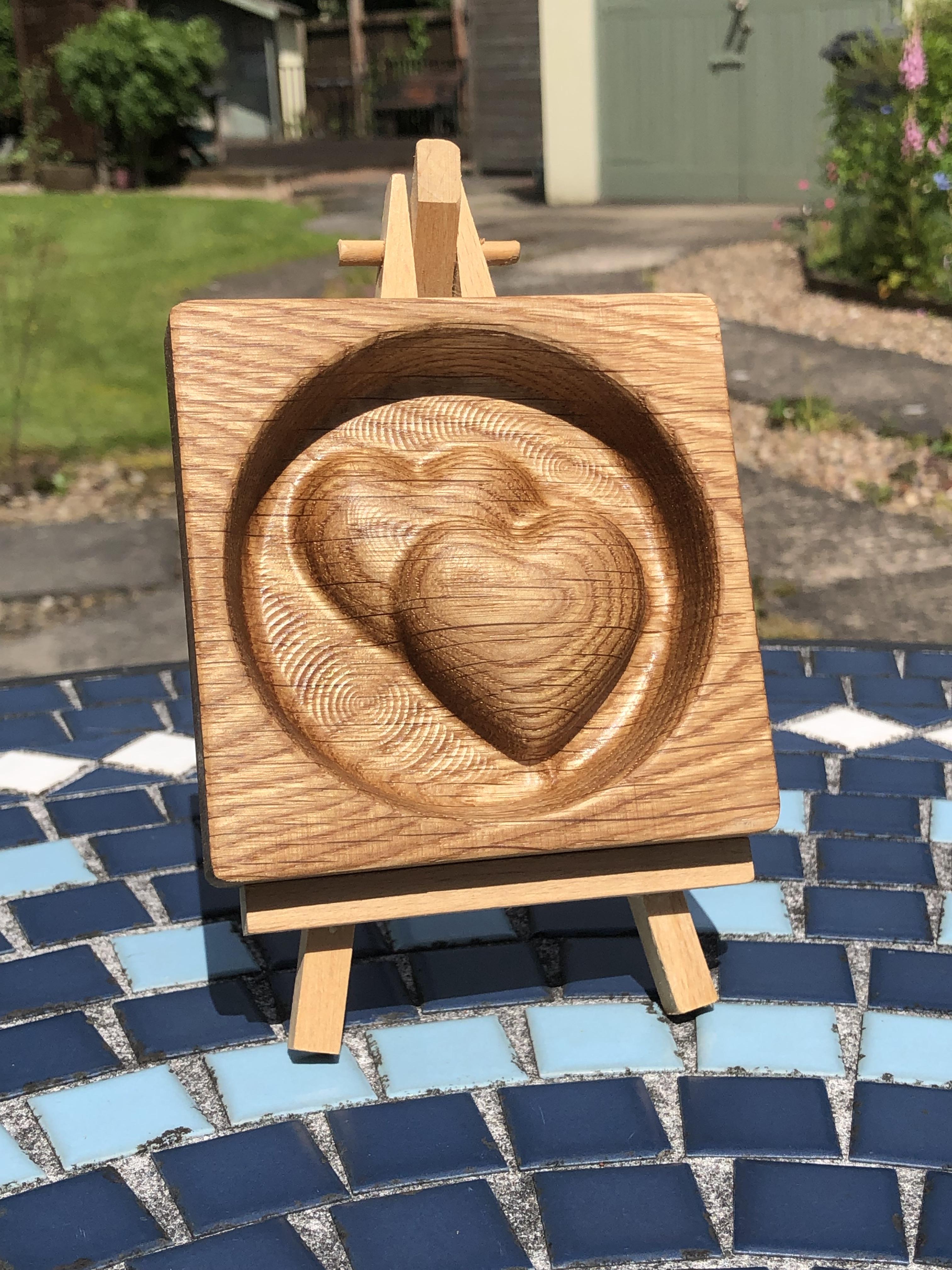
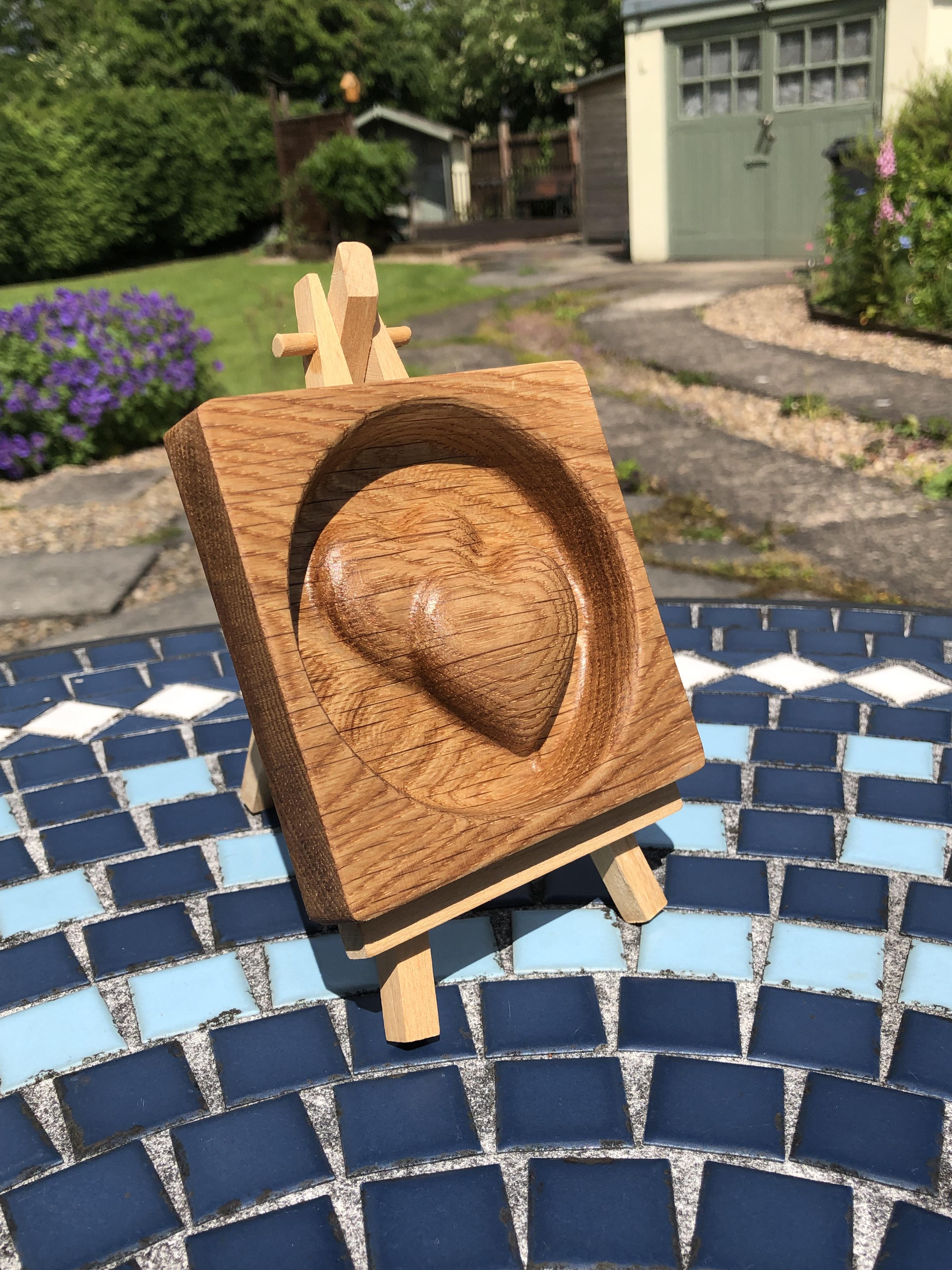
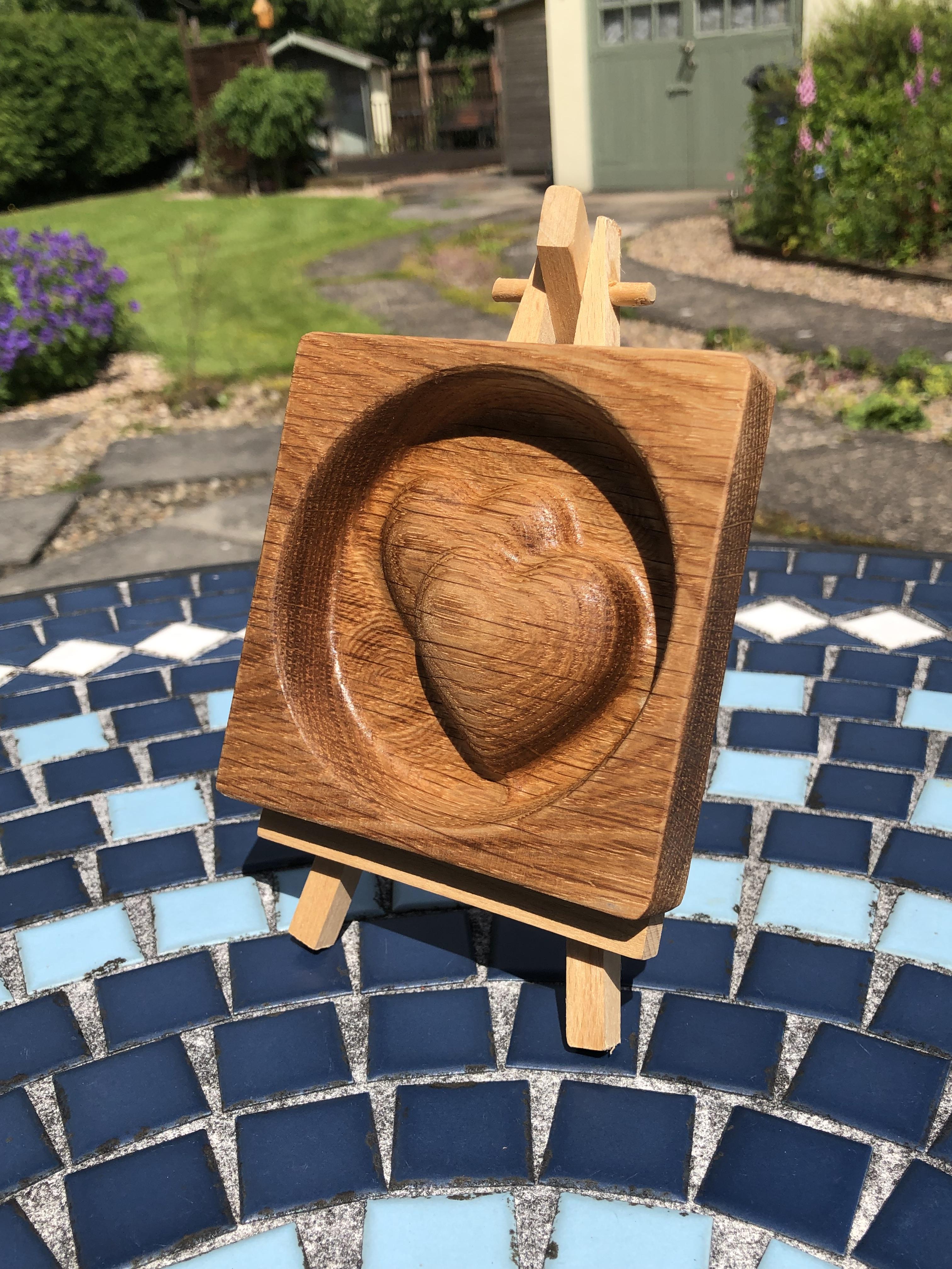
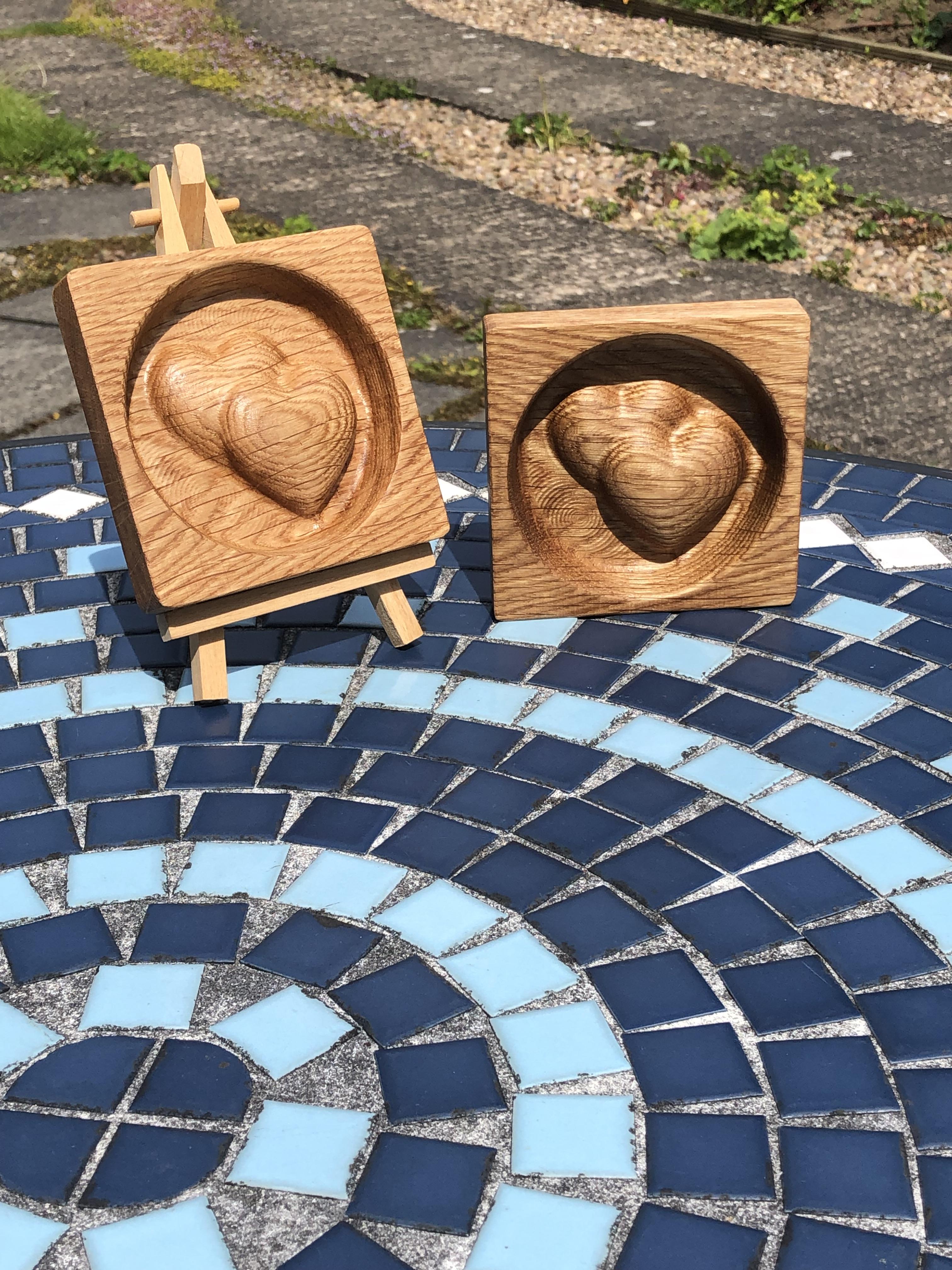
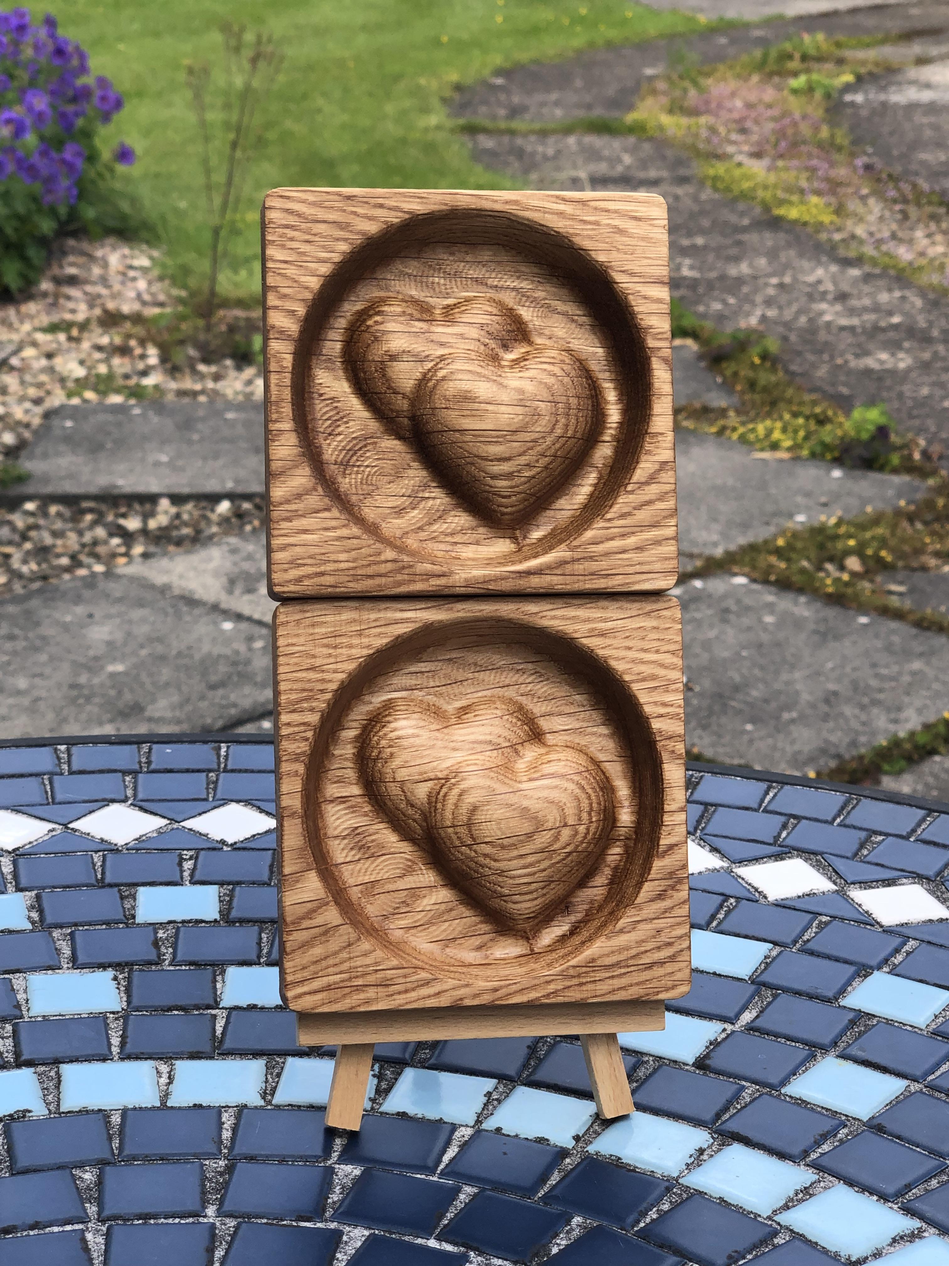
I have done a couple of Instructables on how to carve 3D hearts into a piece of wood, it's usually Oak Floorboard off-cuts as it is in this case.
Please bear in mind here that I am no expert with Fusion 360, I have picked some things up over the years and feel comfortable enough with it to show examples of what can be achieved and put it in Layman Terms hopefully, I've watched countless tutorials only to be left totally confused then tried something myself only to find it not so complicated, I try things, a lot of the time it doesn't work but I keep going until it does etc, this is a pretty comprehensive Instructable with numerous screen shots showing the different processes.
The reason I wanted to show you this time is because a friend of the family has asked if I could make one of these carved hearts but with 2 hearts carved out of the wood, well they want 2 of these for upcoming Family Weddings.
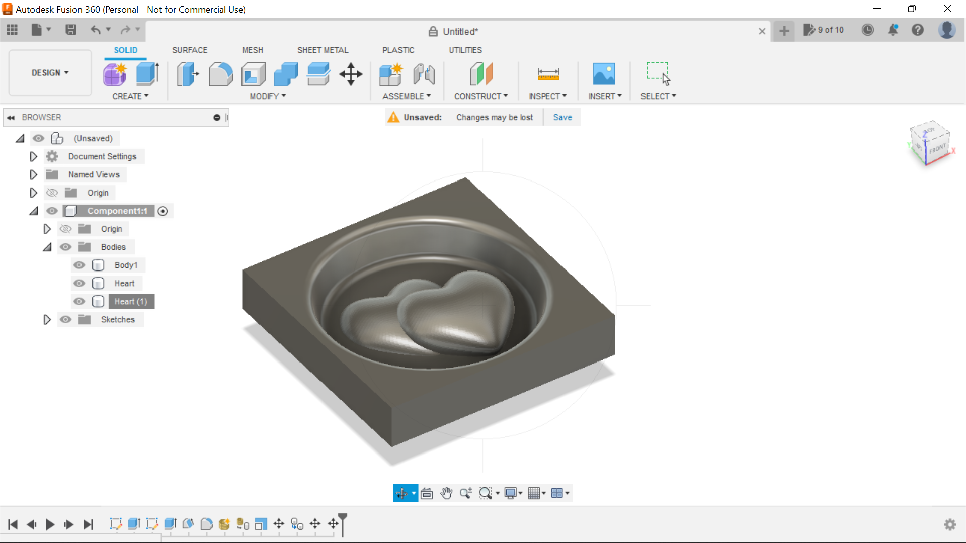
The goal is to create the 2 hearts on top of each other in a circle within a Square and a draft to the circle to taper and fillets to smooth things and then cut the piece out of the stock using tabs to hold in place.
Within this Instructable using Fusion360 we will be using quite a few elements, Create Sketch, extrude, Draft, Fillet, then insert a 3D heart into the design, Use Mesh to convert it into a Solid, then Scale the Heart, Move the Heart around the design, copy the heart and paste it into the design, split body, and finally from a design point of view, combine the 3 Components, then to Manufacturing the Heart, New Set up, Create a 3D Adaptive Toolpath to cut the design out, then a 2D Contour Toolpath to cut the piece out of the stock and adding Tabs to hold the design in place, Phew! there is a lot to get through!
I use Oak floorboard because it's all I have, I managed to buy some off-cuts after someone had an Oak floor fitted, well it was a complete pack and some off-cuts for not much money, and it's ideal for these heart projects, but any hardwood would do, or using the Utilities section in Fusion360 the piece could be 3D Printed
The Hearts make great gifts for Weddings/Anniversaries/Engagements etc, they can be used as an ornament or a trinket tray and are very tactile and making something from nothing is always good.
I will be using my trusty Ox Belt driven CNC for the Cutting operation and consequently I will be using the correct PPE throughout the cutting operation, I use a full face dust mask these days as breathing in wood fibres is not good for you whatever type of wood it is.
Time for a Heart to Heart with Heart on Heart:)
Supplies
Oak or any hardwood off-cut 18.5 thick in this case
Boiled Linseed Oil or Danish Oil or Varnish if you prefer.
Medium Sandpaper
Fusion 360
CNC Machine
6mm Ball End Router Bit
The Design Process With Fusion 360
.png)
.png)
.png)
.png)
.png)
.png)
.png)
.png)
.png)
.png)
.png)
.png)
.png)
.png)
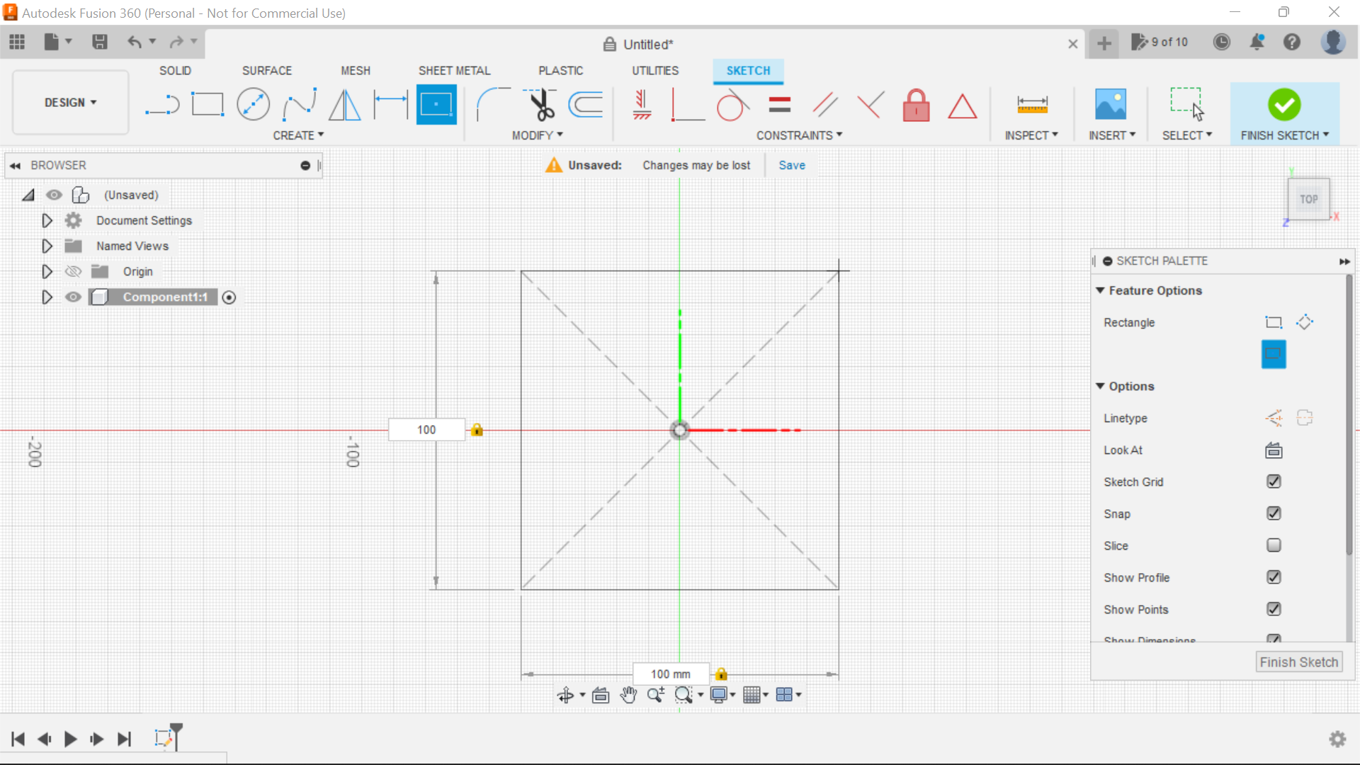
To start with in Fusion 360 we create a new component and we will be selecting the Top plane to sketch from,
Selecting the centre rectangle tab, we create a square 100mm x 100mm but this can be any size you want really.
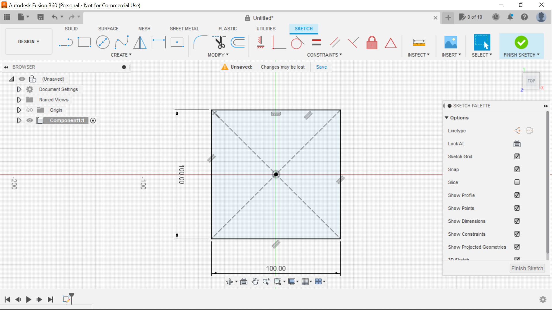
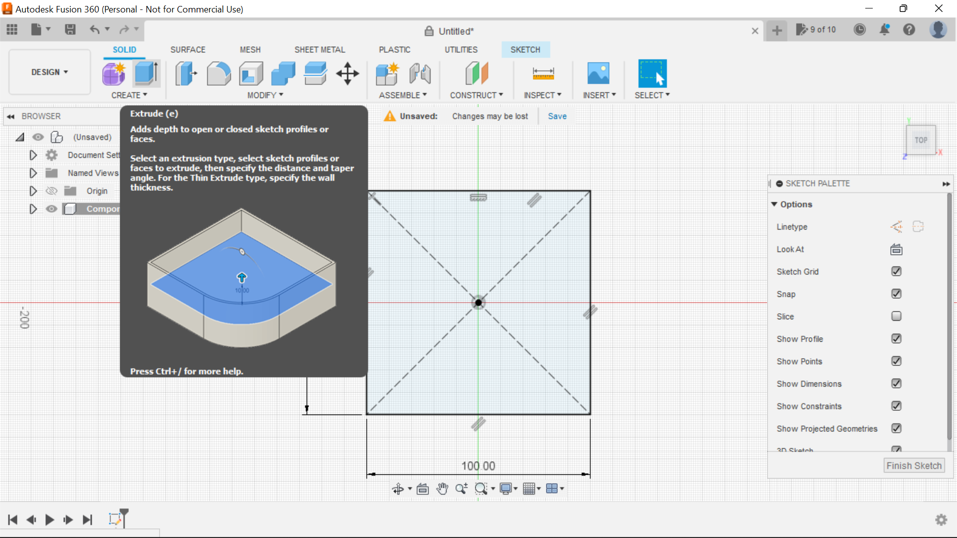
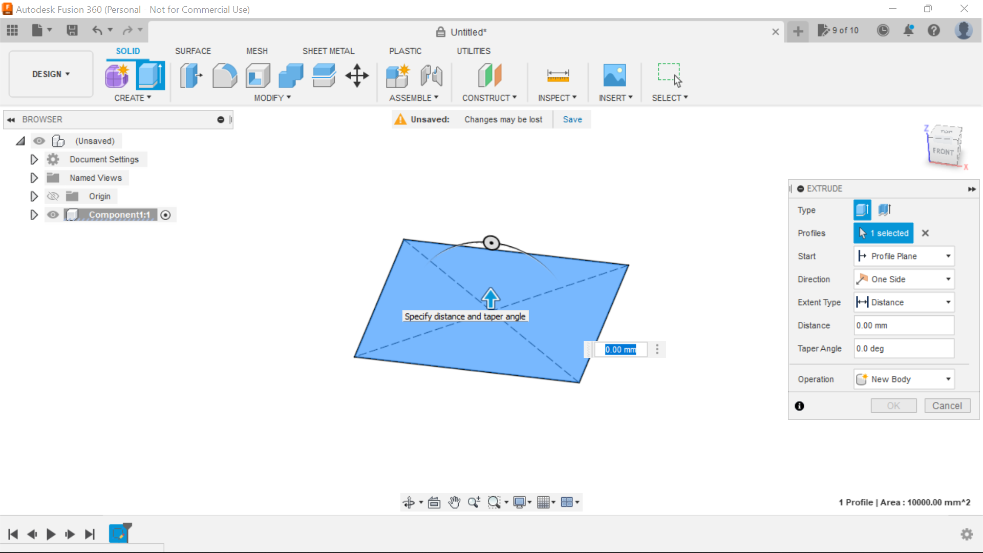
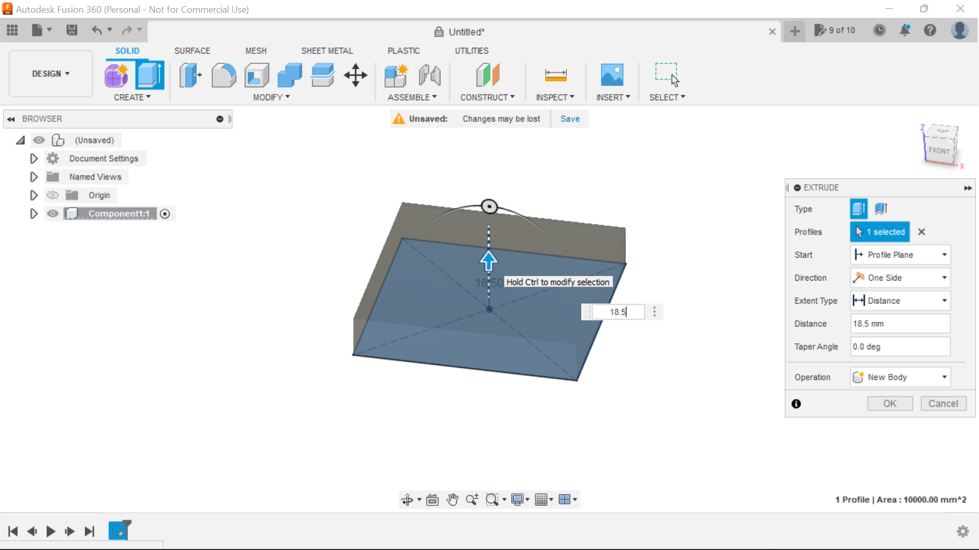
Extrude the square to your material thickness, in this case its 18.5mm.
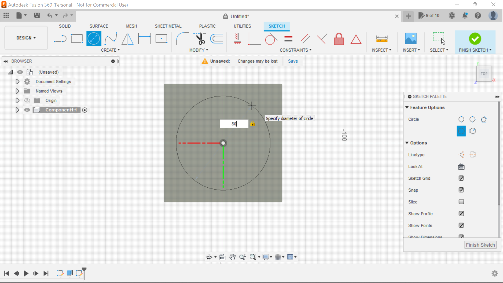
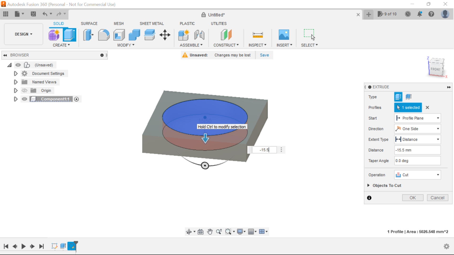
Selecting the Centre Diameter Circle we create a circle of 80mm and then extrude this to -15.5 giving us a 3mm base so to speak.
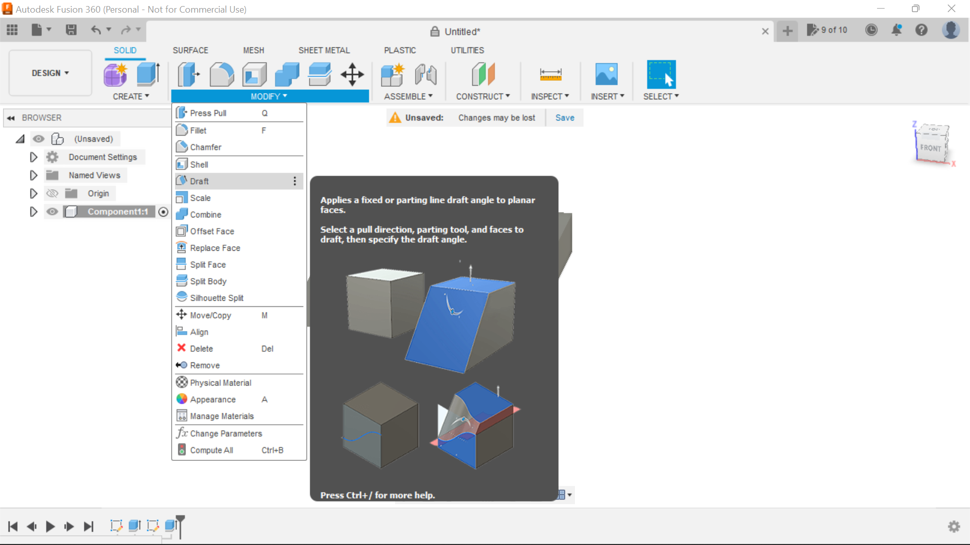
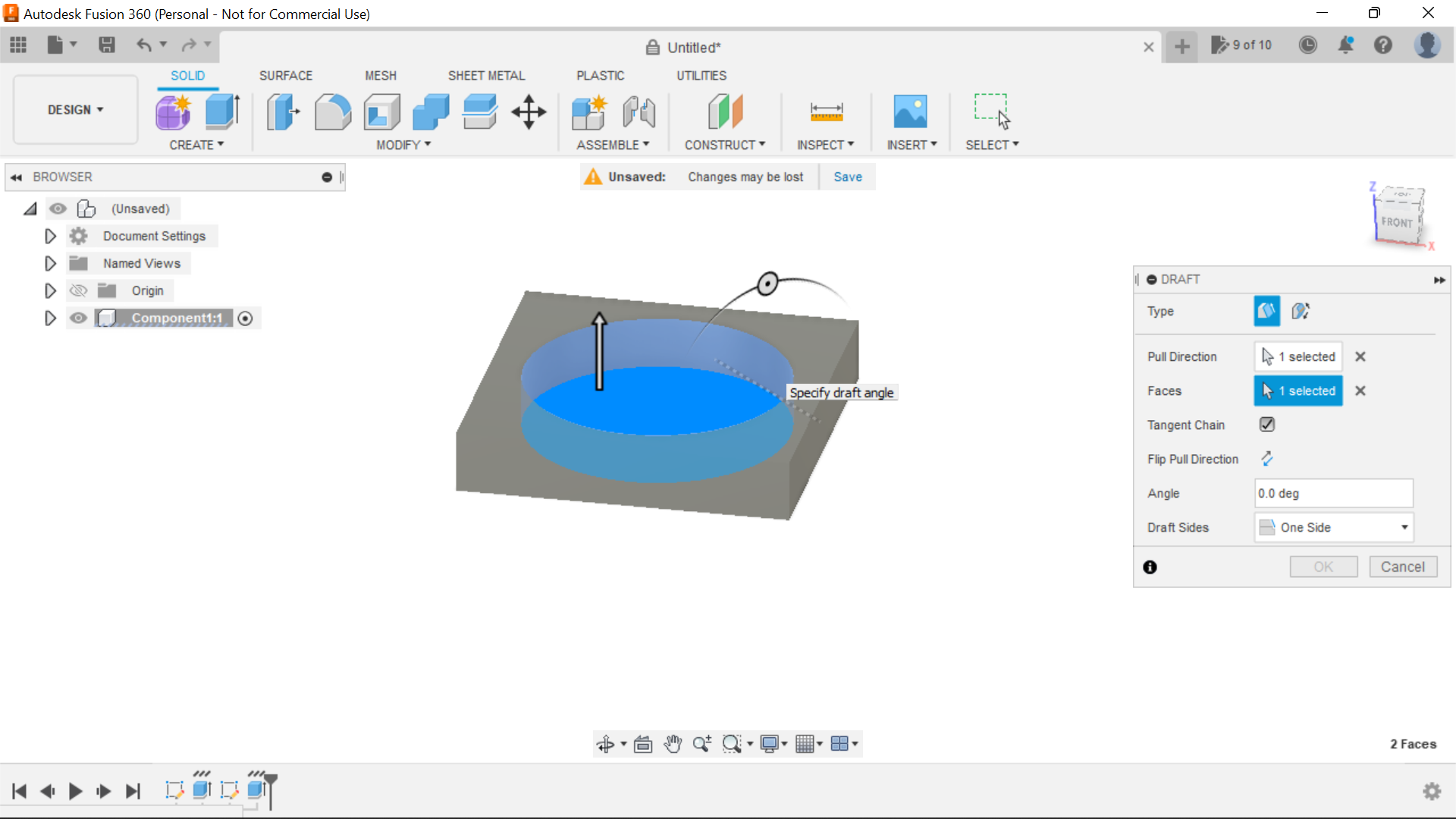
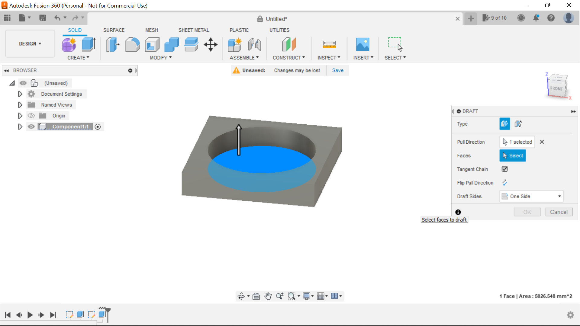
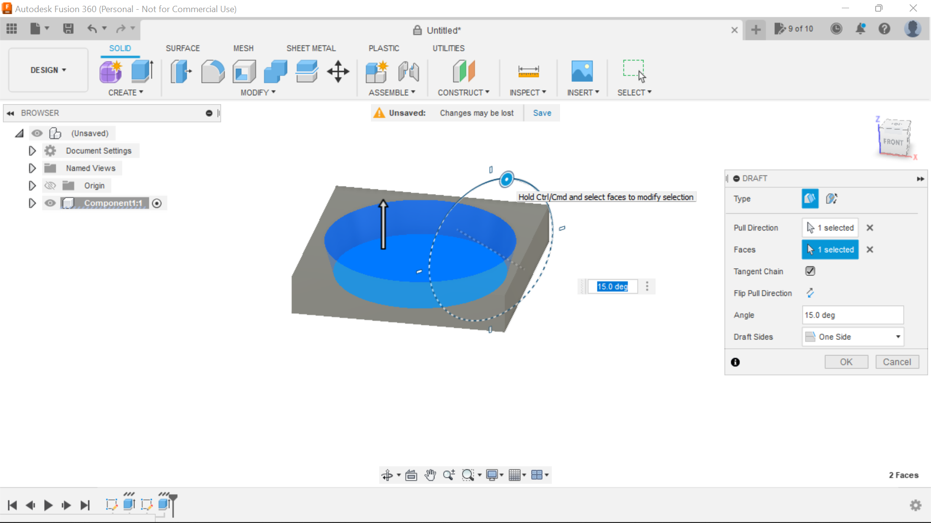
Selecting the draft tool, we can now create a taper of 15 degrees outwards on the circle, to create the draft you click on the bottom of the circle then then click anywhere on the extruded wall of the circle, manoeuvre the piece so you can see the wheel to adjust the draft or just add 15 degrees in the dimension box and click ok.
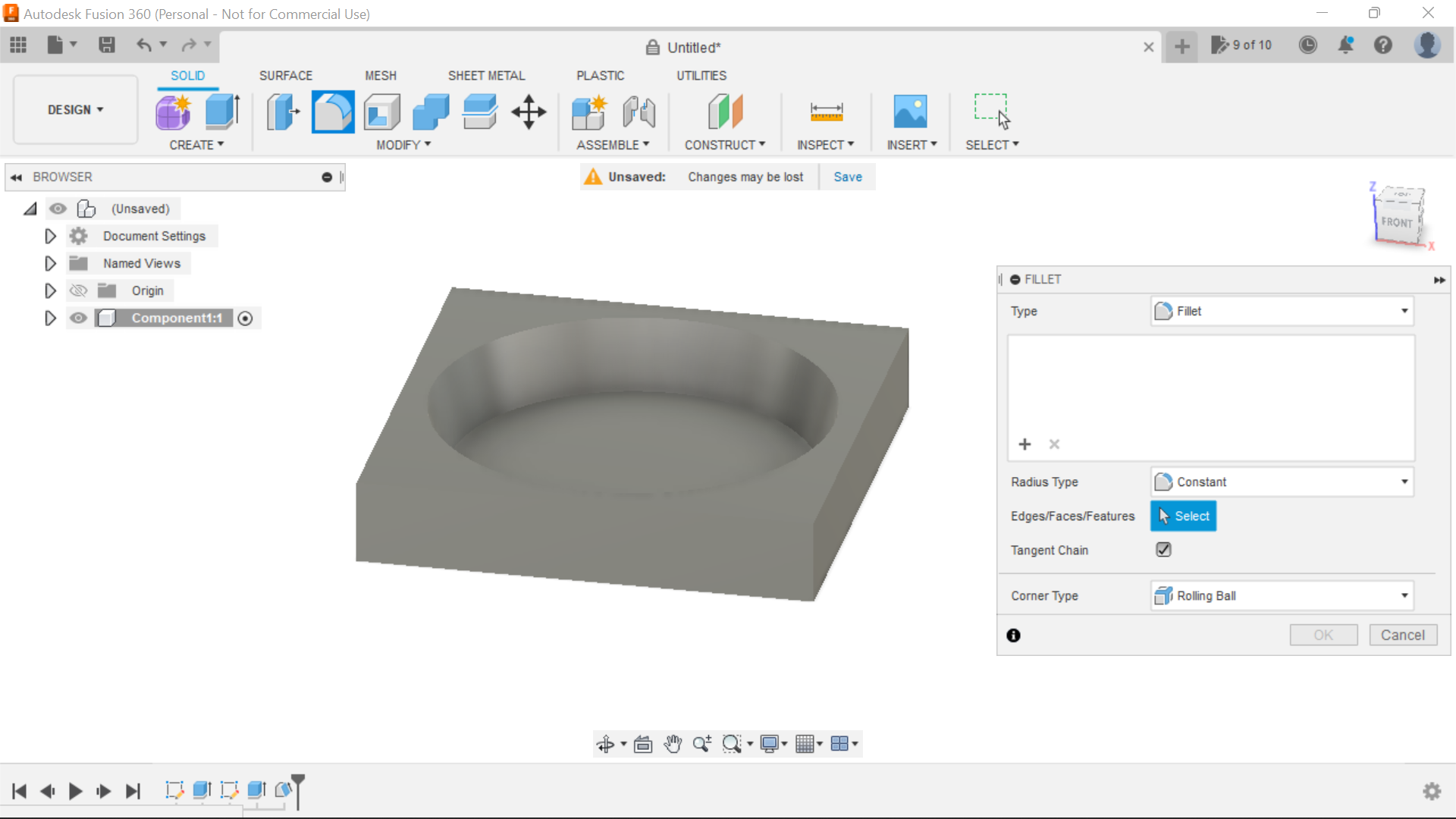
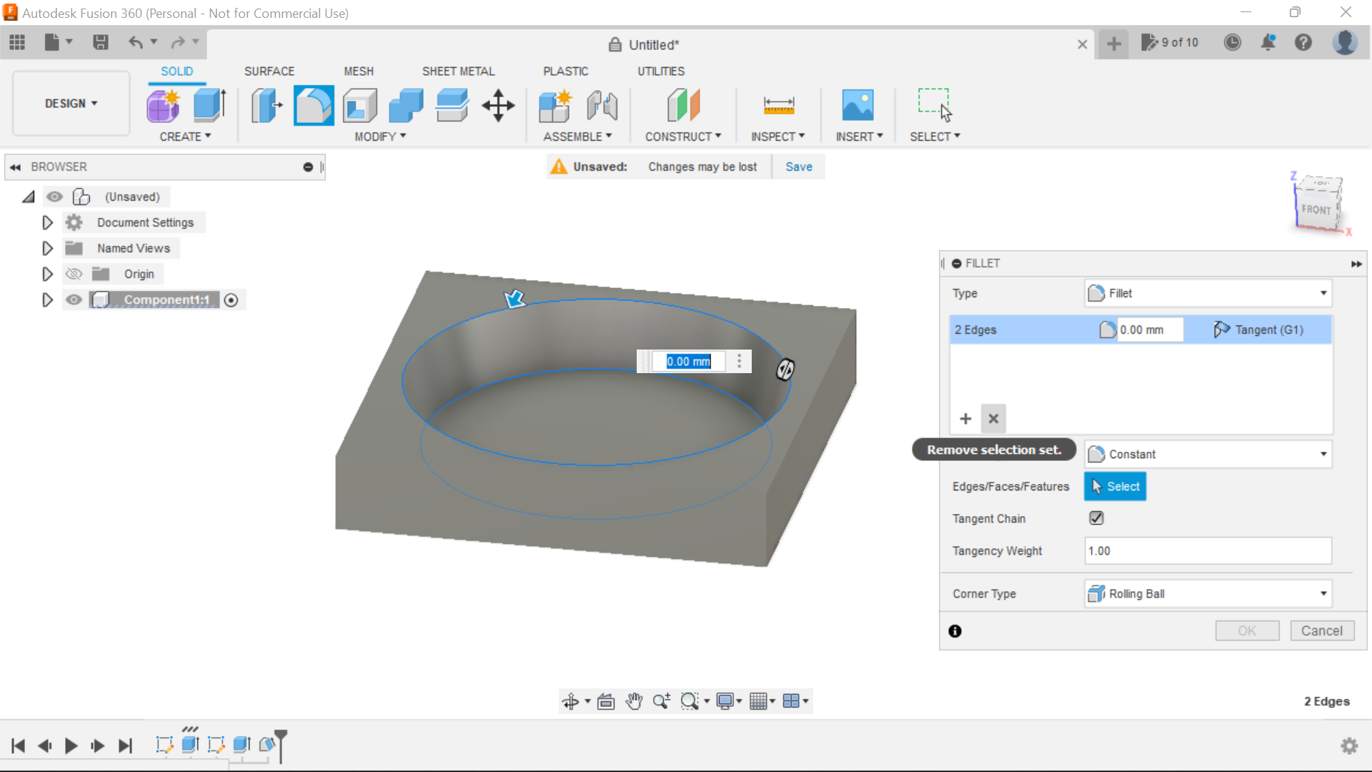
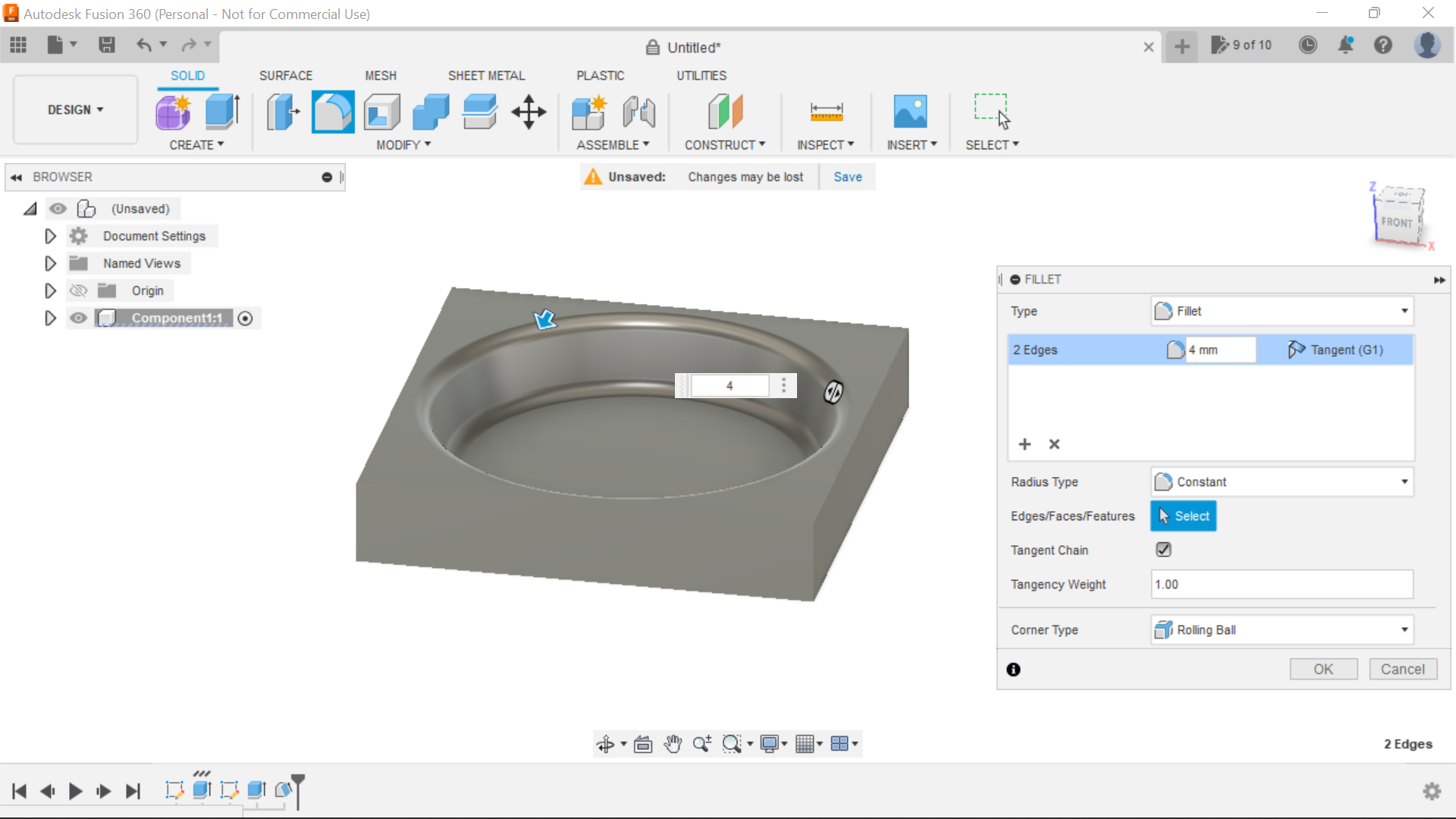
To finish this particular operation we add a fillet of 4mm to the top and bottom edges of the circle for decorative purposes.
So this is the platform for our next process which involves importing a 3D Heart STL firstly onto our desktop then Inserting it into the design, make it a solid, then scale the heart and place it in our design.
Importing a 3D Heart Stl , Inserting Scaling and Positioning
.png)
.png)
.png)
.png)
.png)
.png)
.png)
.png)
.png)
.png)
.png)
.png)
.png)
.png)
.png)
.png)
.png)
.png)
.png)
.png)
.png)
.png)
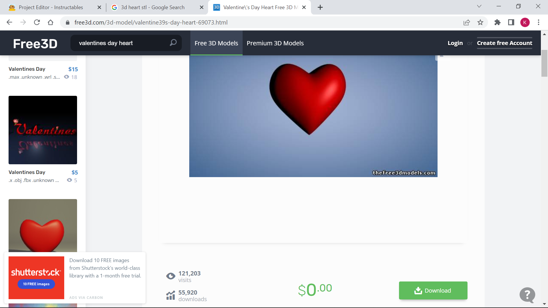
In this section we have to find a free 3D Heart STL online I opted for Free3D and chose one from there for this design.
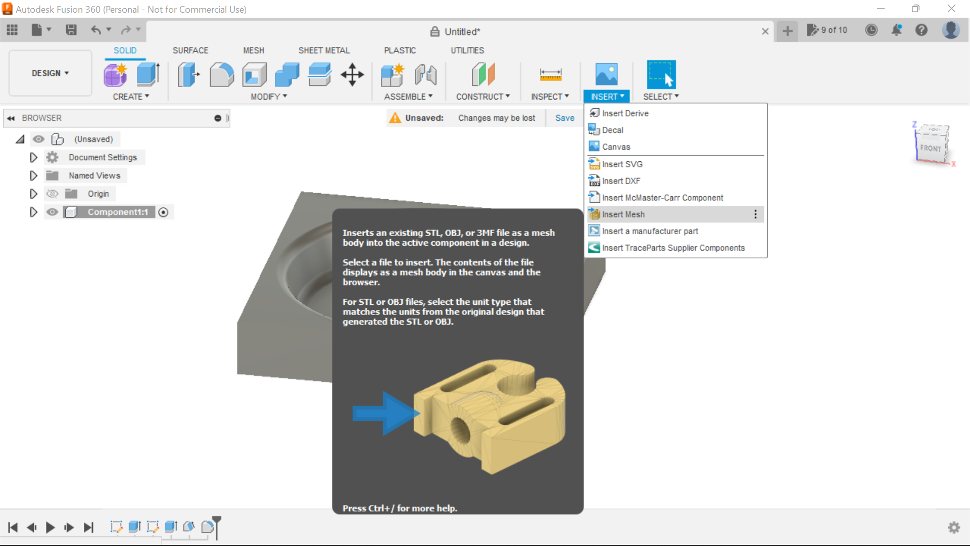
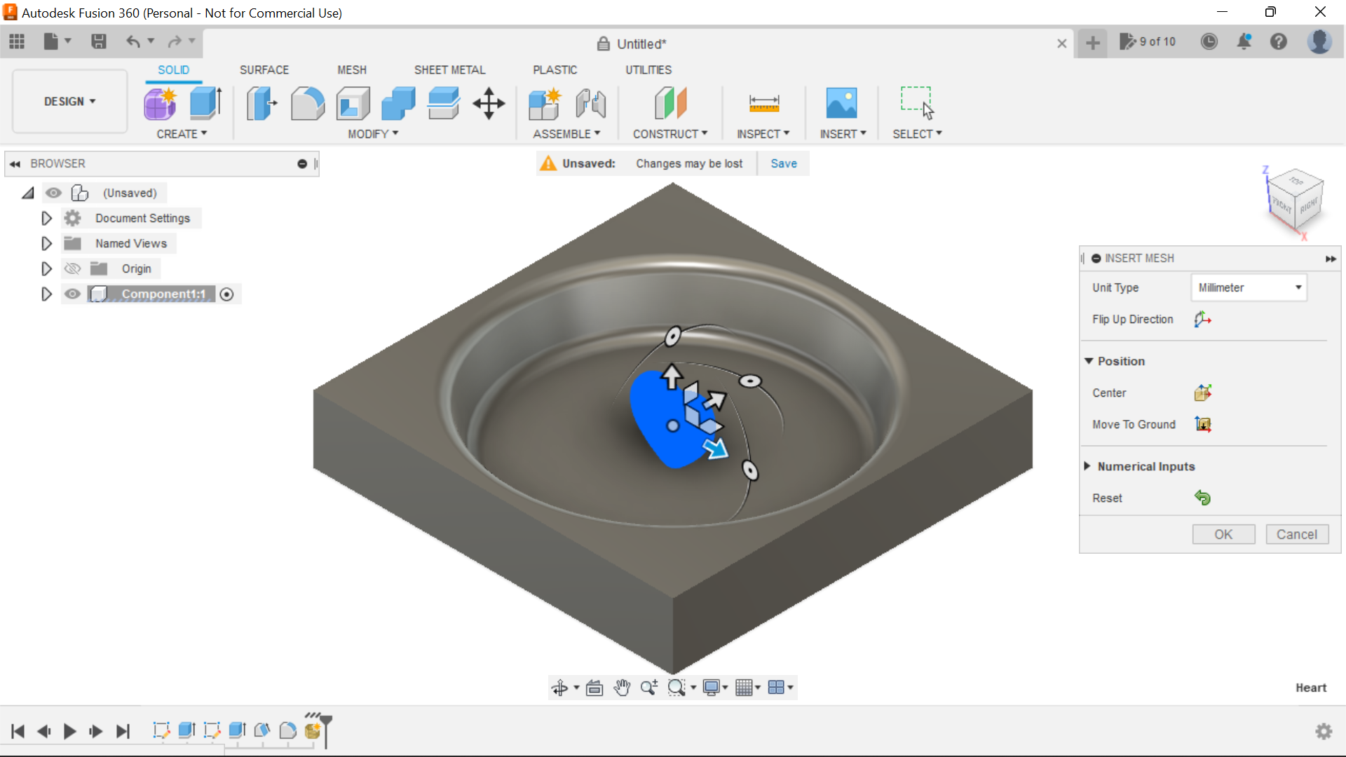
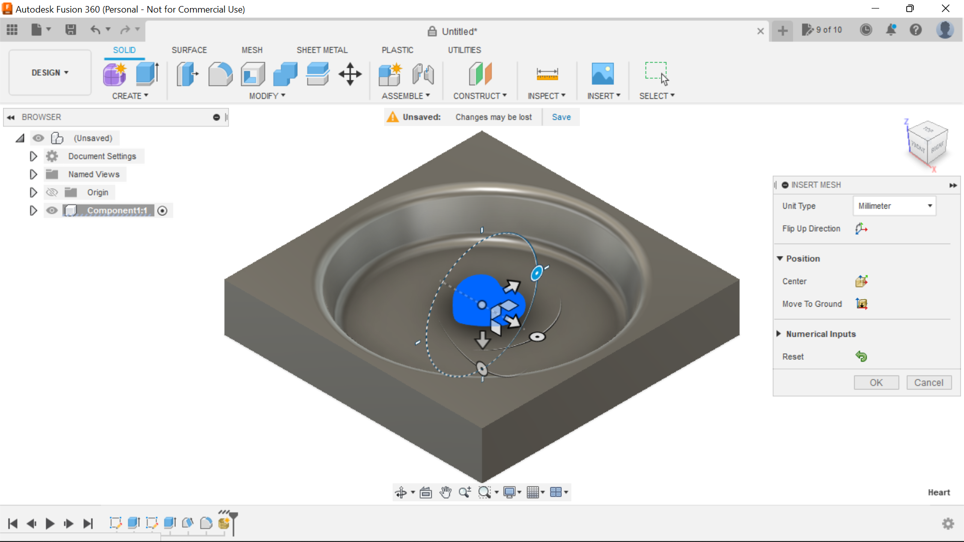
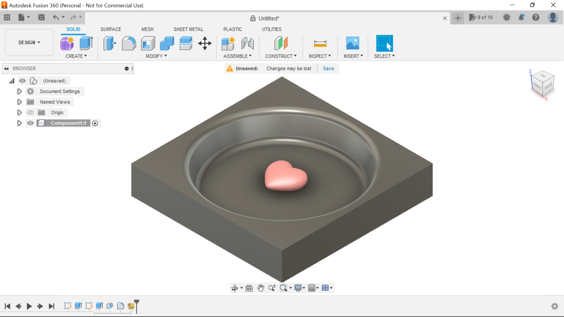
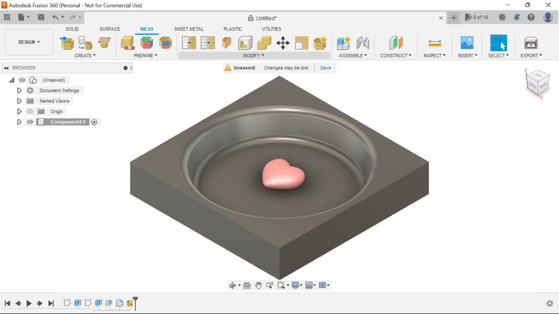
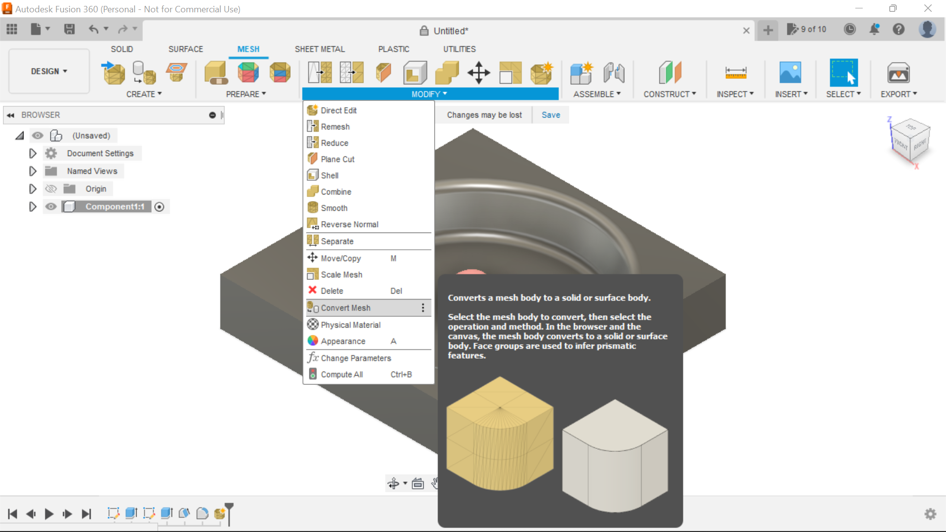
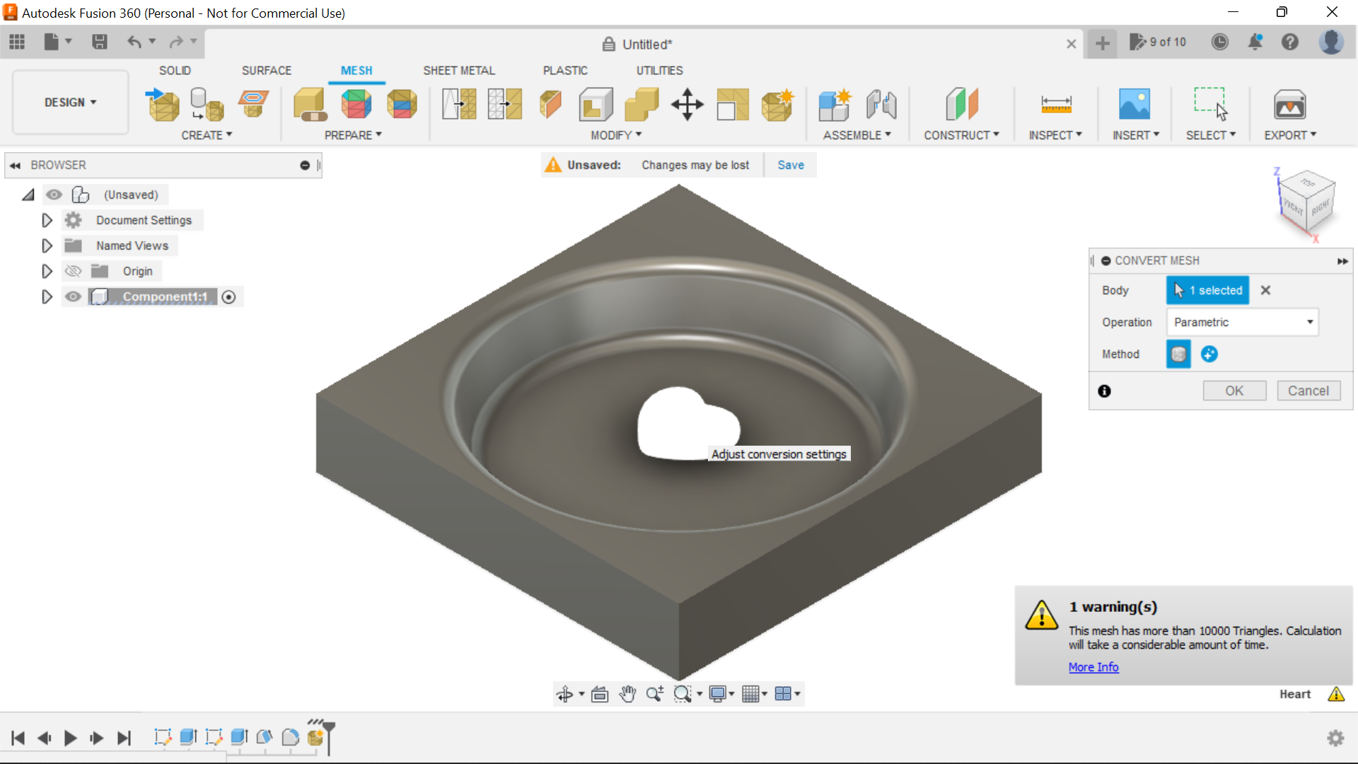
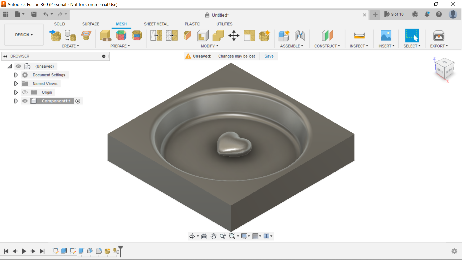
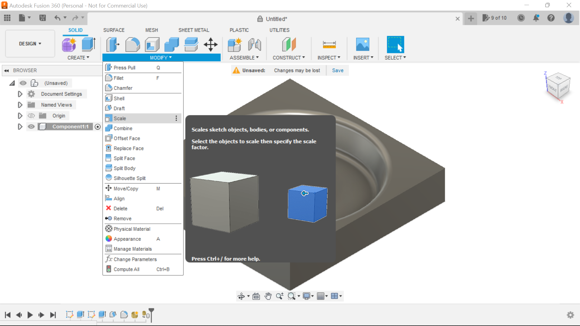
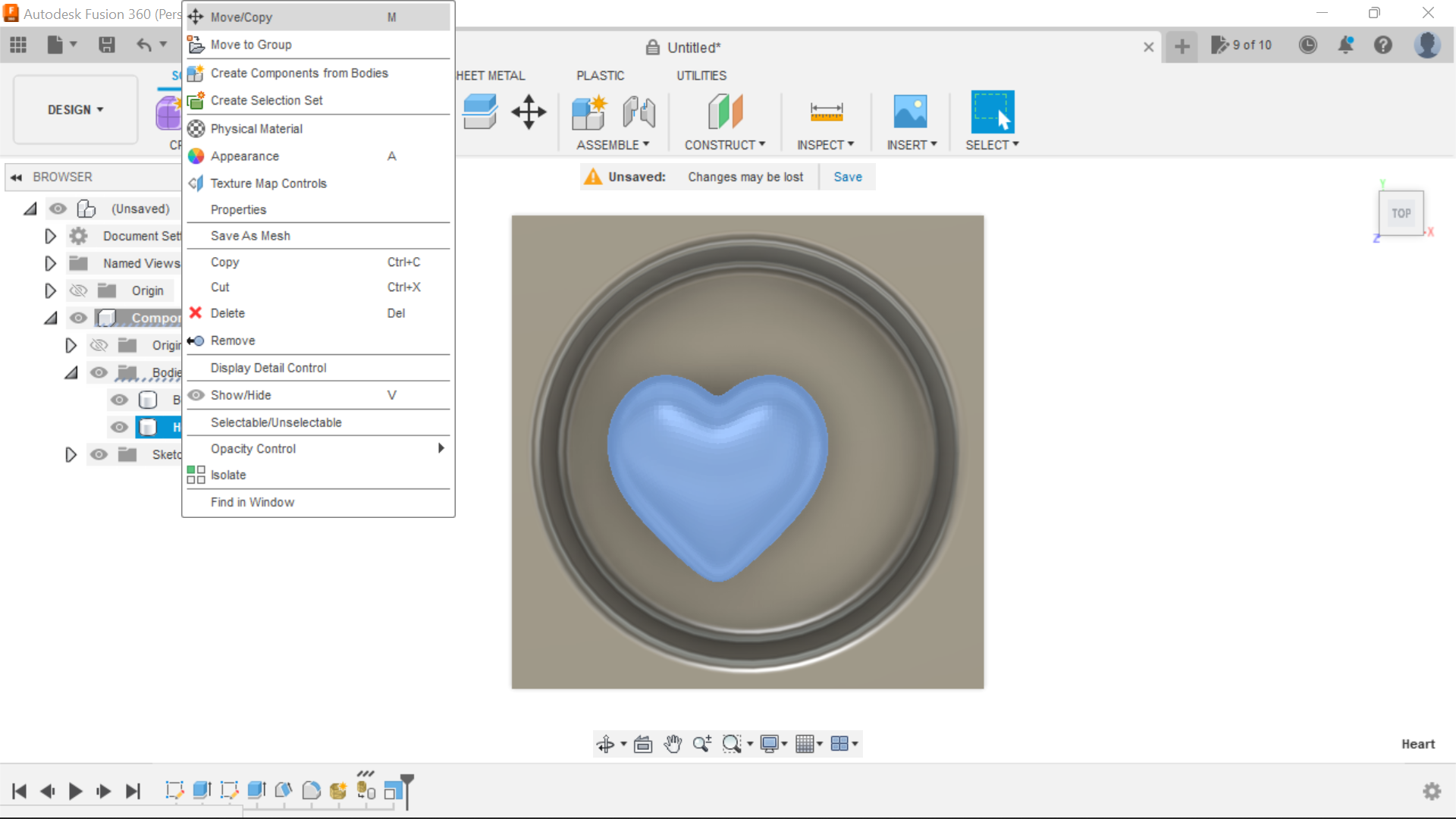
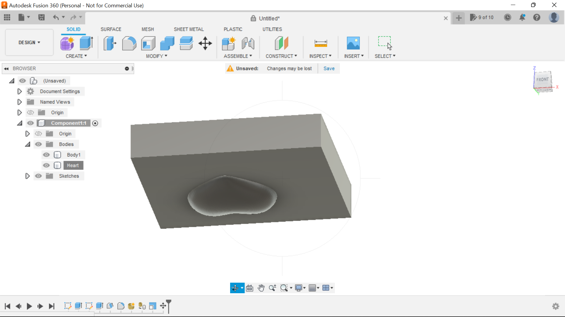
We have to insert the Heart into the design and to do this we select Mesh from the Insert tab, in my case the heart is inserted vertically, so using the rotate wheel I manoeuvre until its lying flat and then click ok, open the Mesh tool in Fusion 360 from here we can select the tab convert mesh in the Modify section and this creates a solid body for us which we can now scale to size and position within the design.
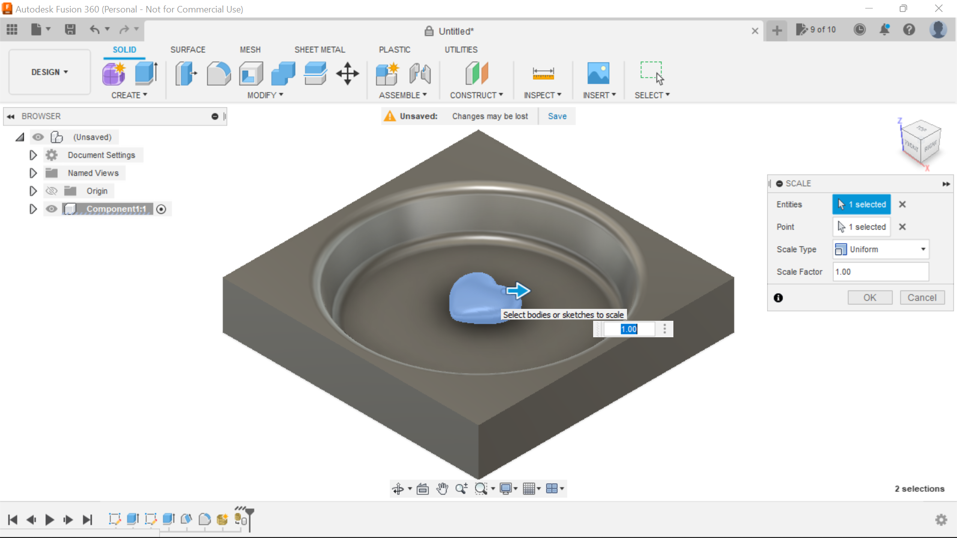
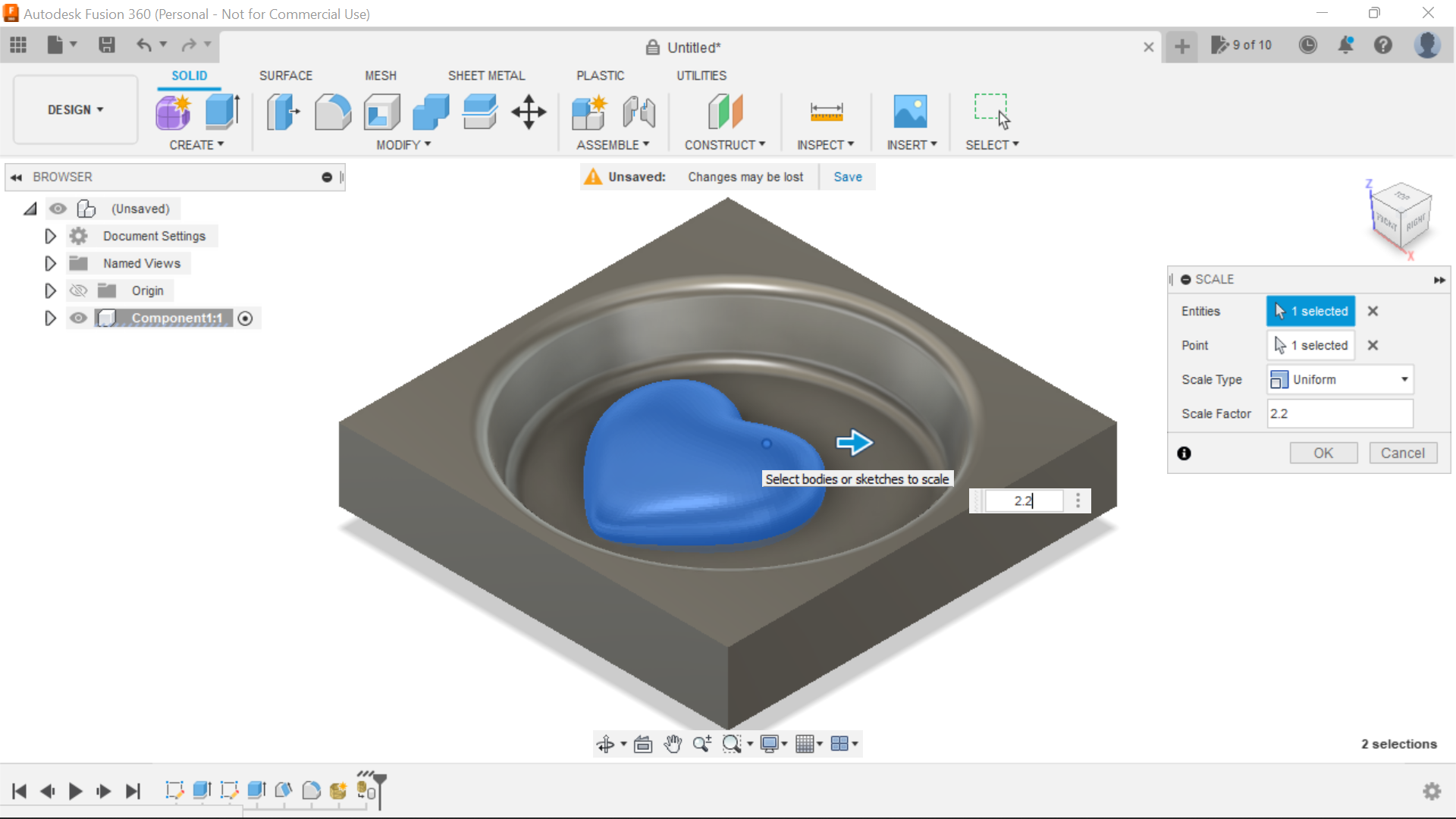
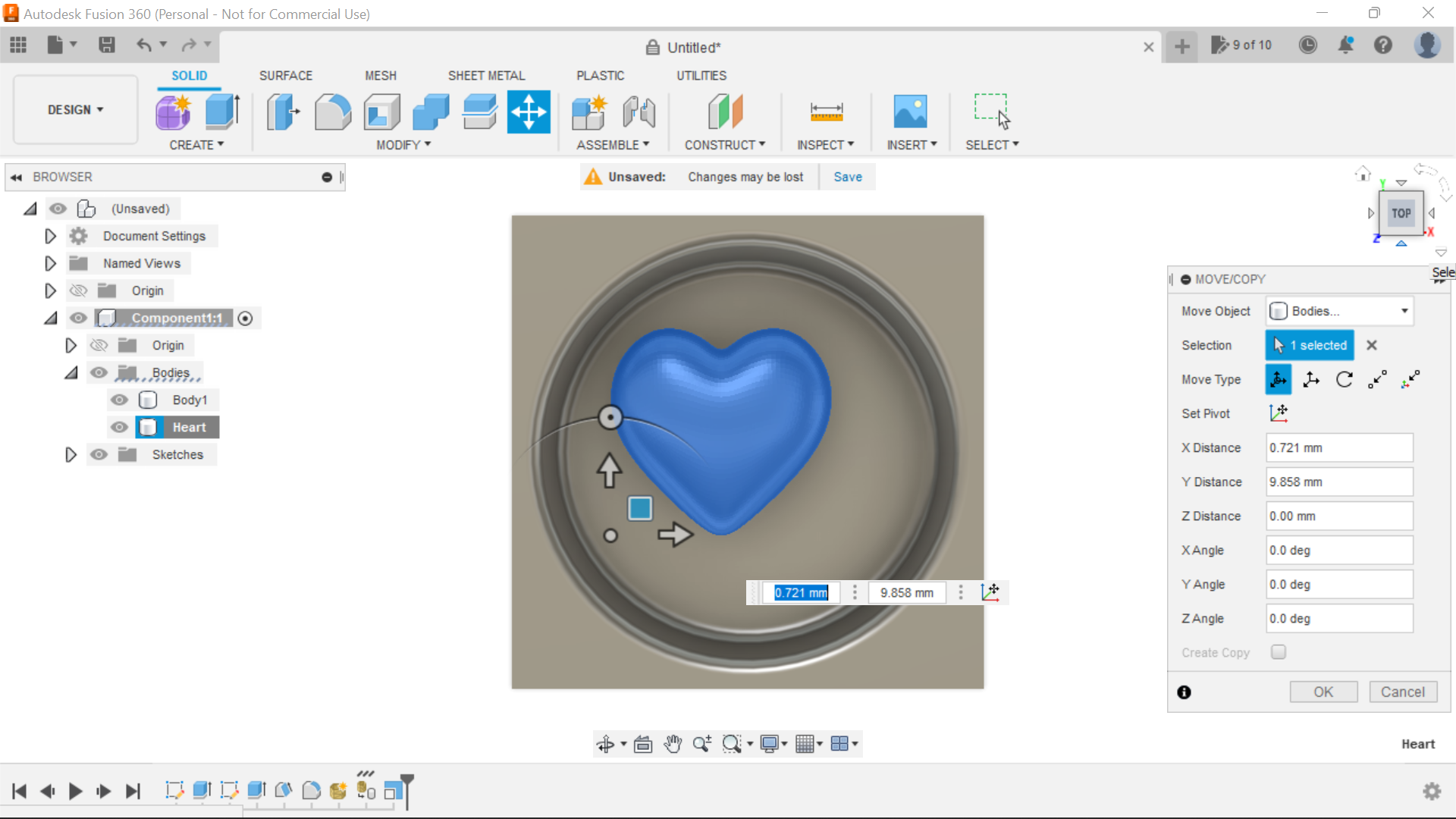
I played with the scale dimensions until visually it looked the right size(2.2 in my case) and would fit into the circle nicely, bear in mind that in this case I am using a 6mm Ball end bit so I'm aware of this with the gap I'm leaving between the Heart and the wall of the circle.
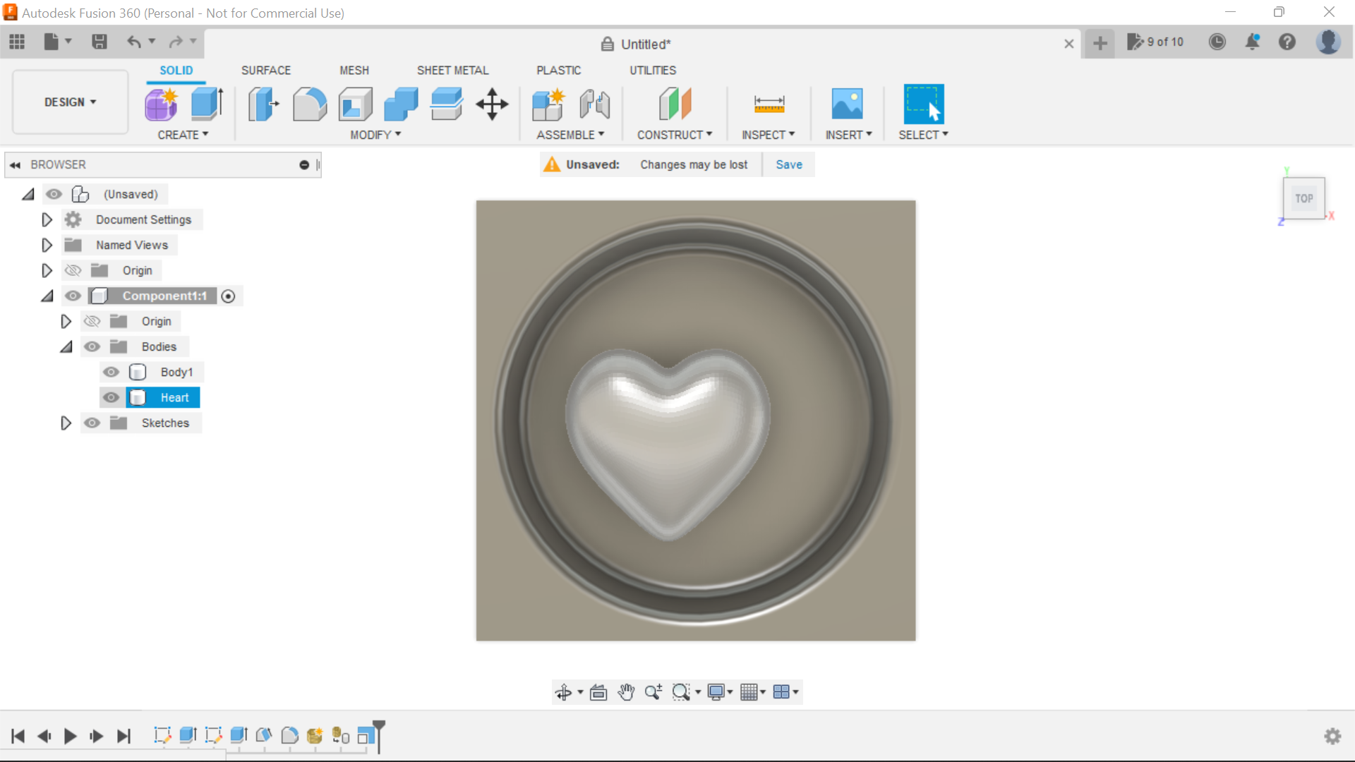
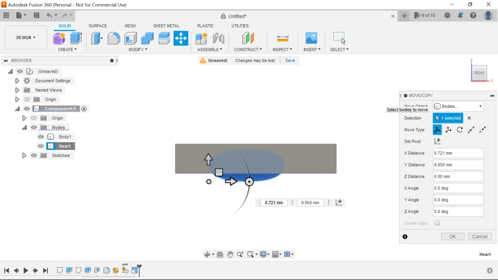
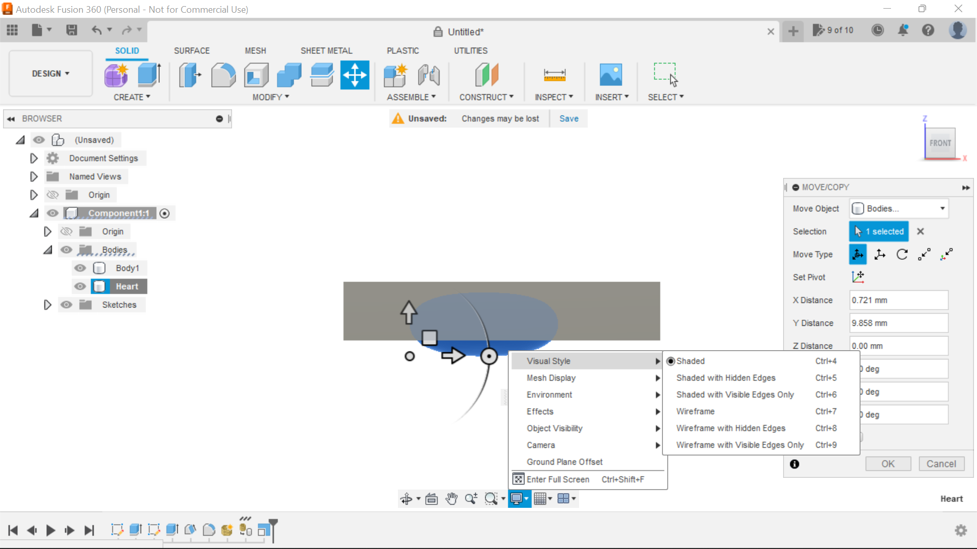
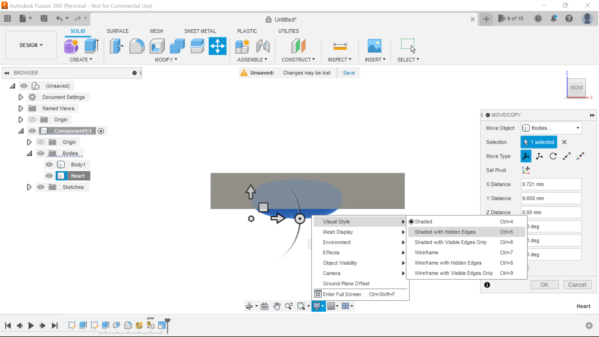
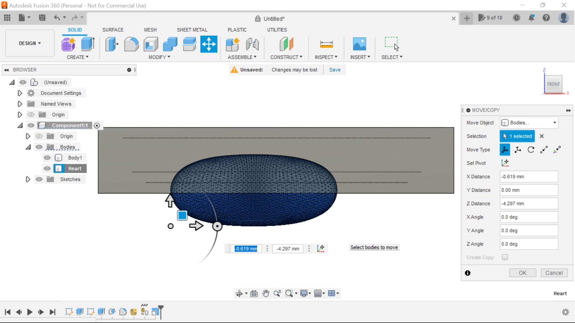
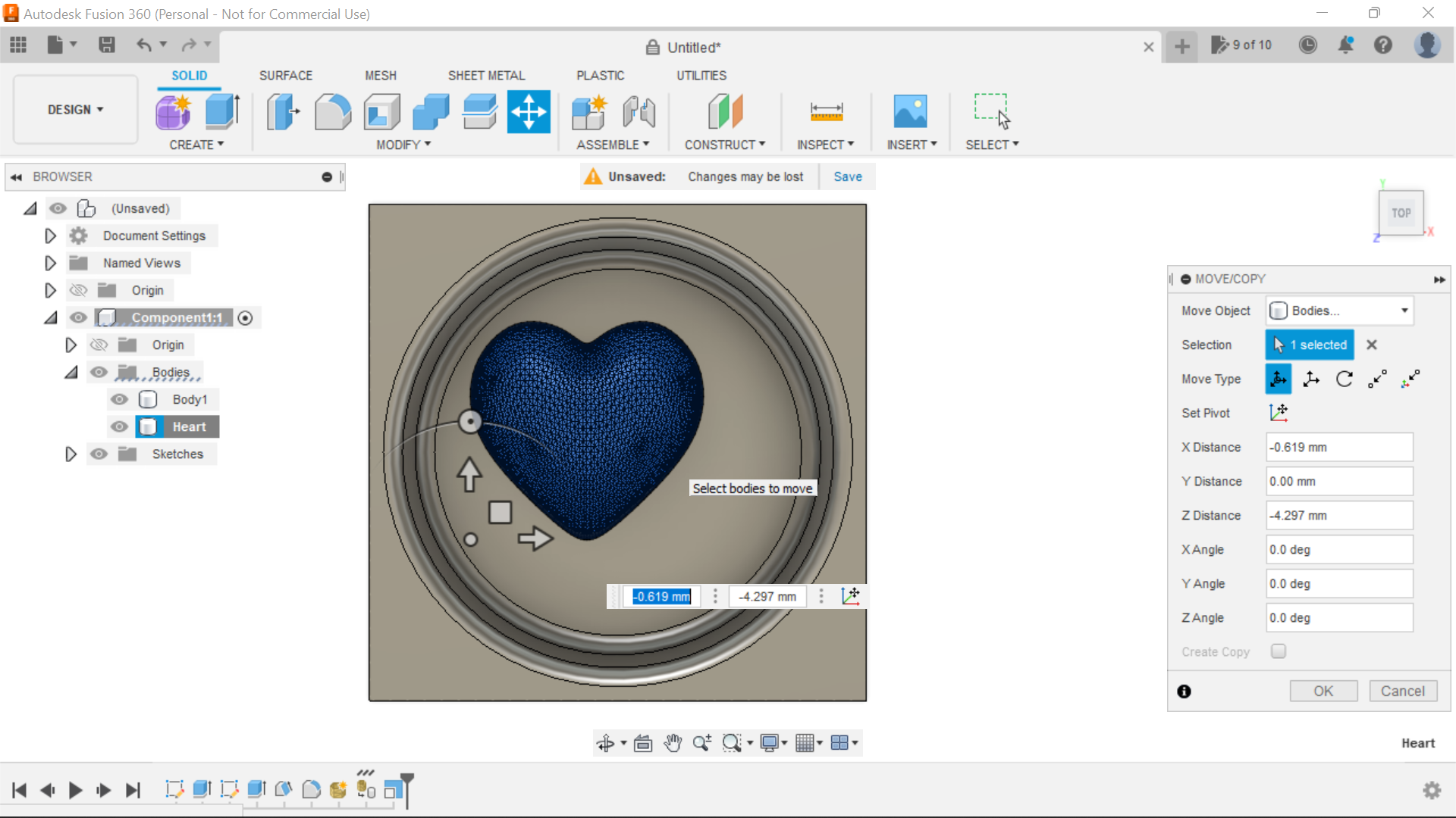
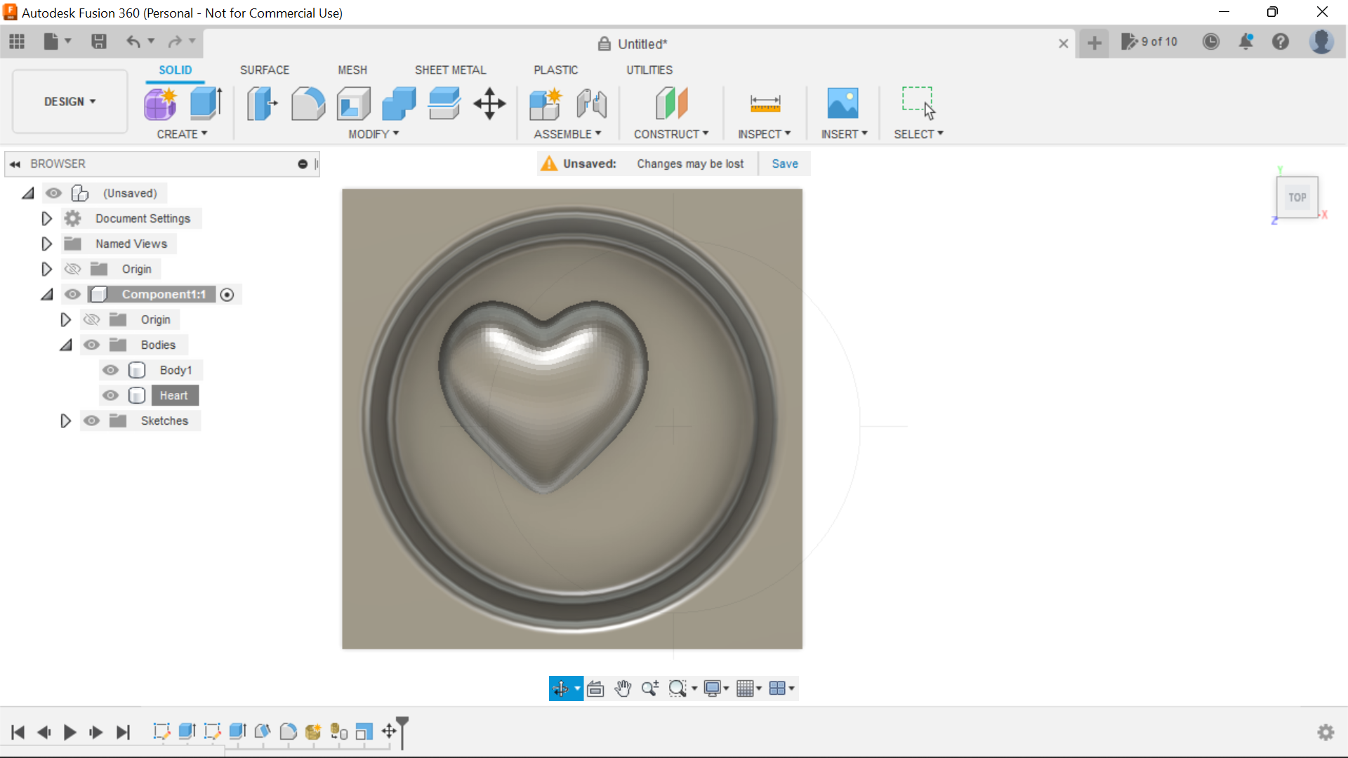
Using the Top and Front views manoeuvre the heart to the position where you want it, bearing in mind we have to fit 2 Hearts into the cavity, the 2nd heart will sit on top of the first and we want to see the shape of the top heart more or less fully, toggle between shaded and shaded with hidden edges in Visual style to help with positioning as in the screen shots, use the top view first and then the front, when happy, click ok.
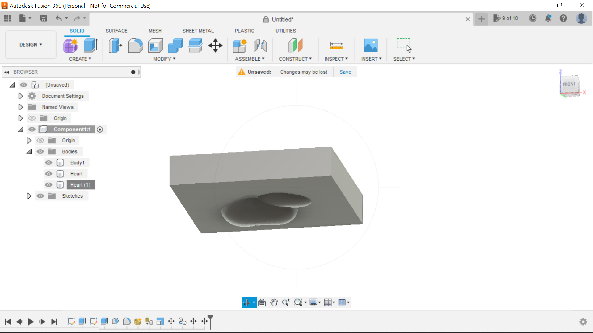
With sinking this first Heart into the cavity, you will notice that the heart is protruding through the bottom of the design, we will take care of the later with split body.
We can now move onto the 2nd Heart:
Adding a 2nd Heart to the Design.
.png)
.png)
.png)
.png)
.png)
.png)
.png)
.png)
.png)
.png)
.png)
.png)
.png)
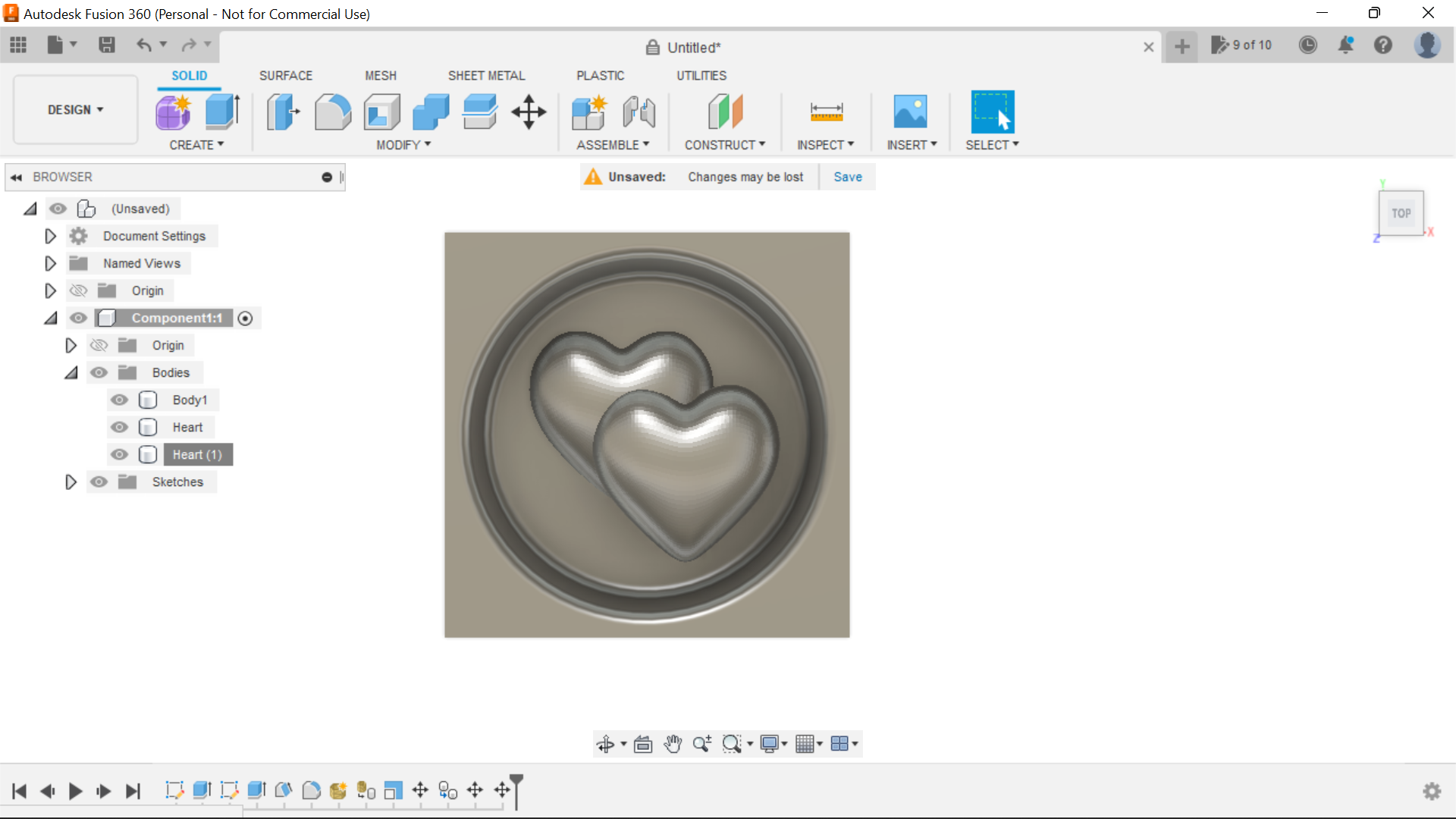
In this section we add the 2nd Heart, we split both bodies and then combine everything.
Before we start this part, In the browser section where it says Bodies, right click on this and click on Turn bodies into components and we will have a component to work with.
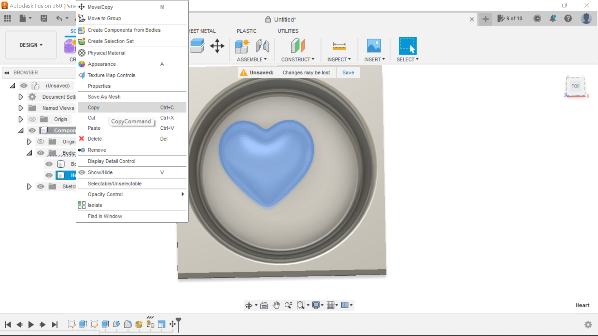
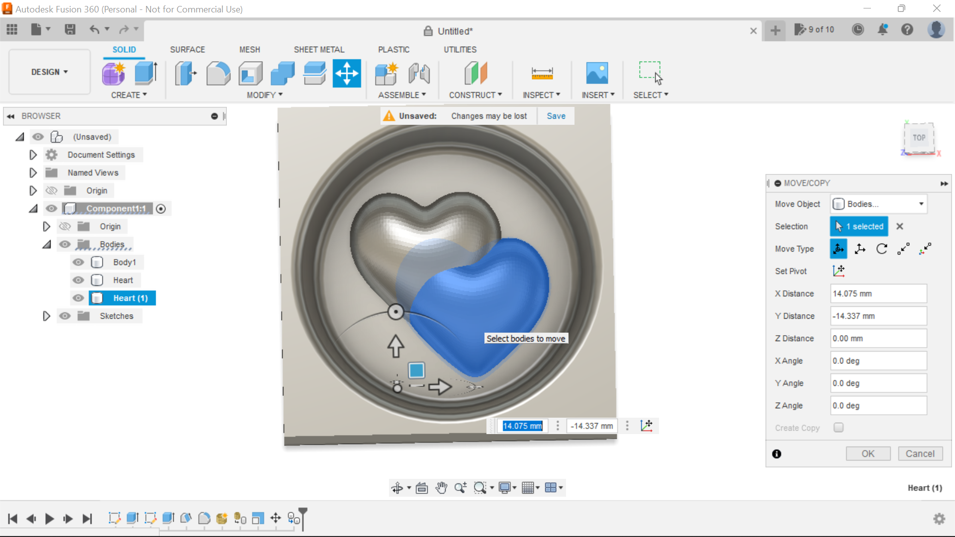
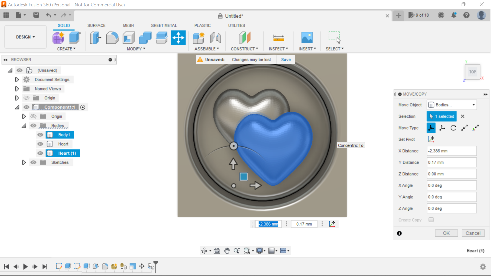
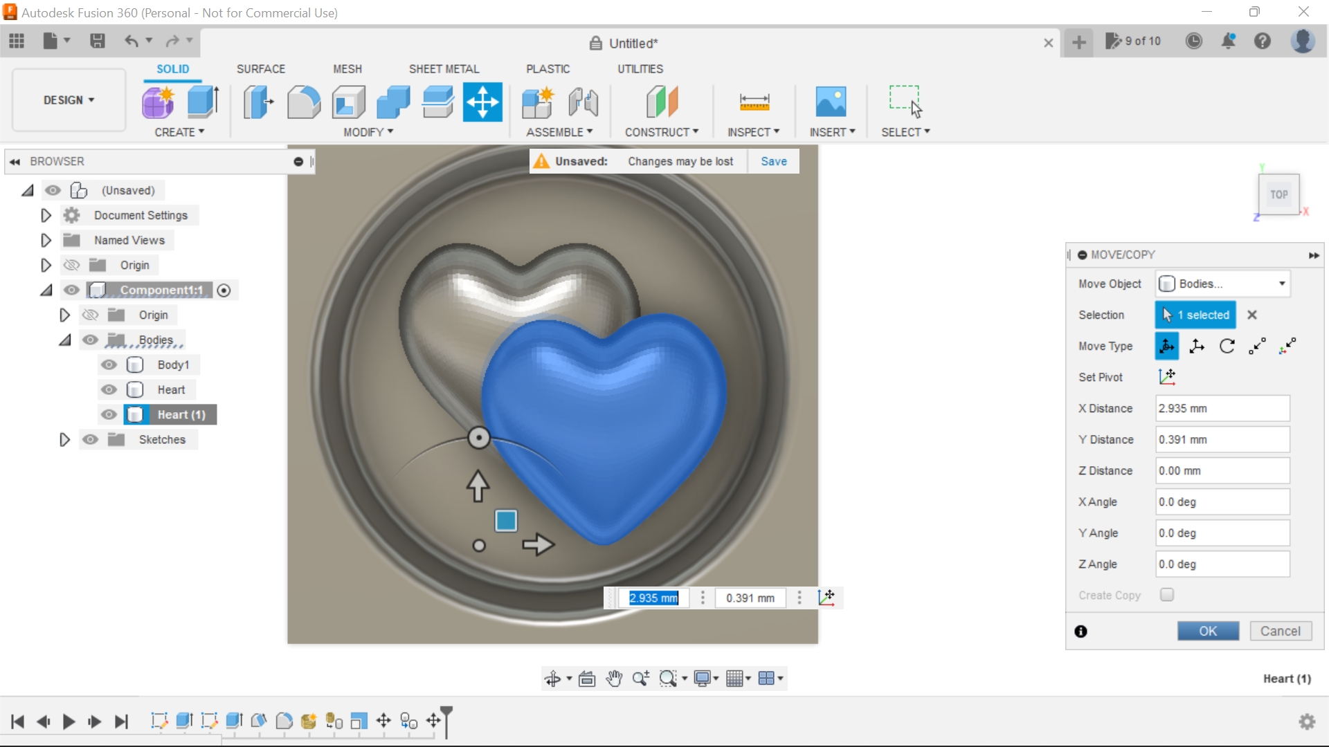
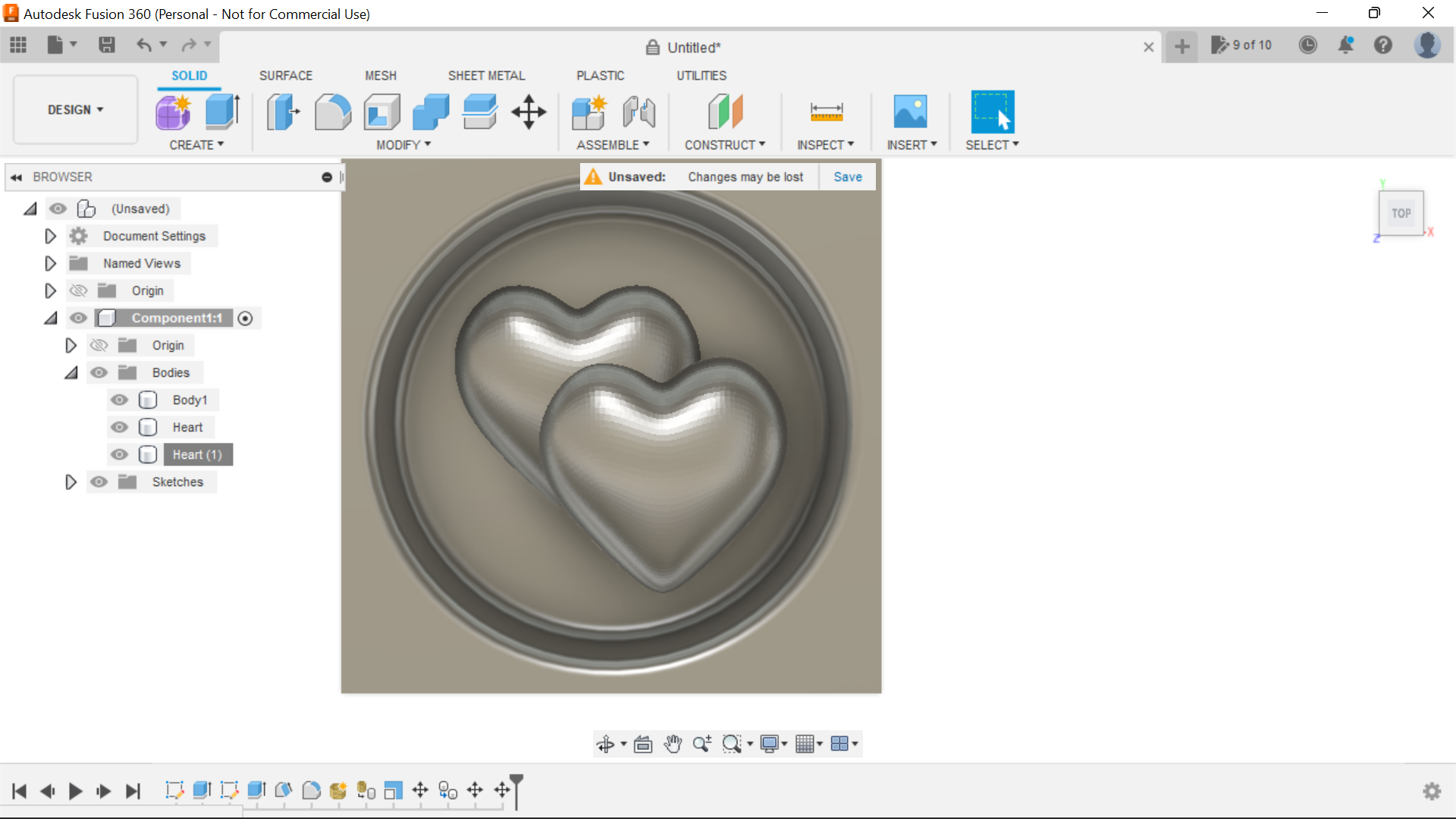
In the Browser section select the 1st Heart, the heart will turn blue, right click the mouse and copy and then right click and paste, we can now manoeuvre the copied Heart into the position where we want it, same as the first time use shaded and shaded with edges and Top and Front views to get it into the right position and depth once again allowing room for the bit at the edges, when you are happy, then click ok.
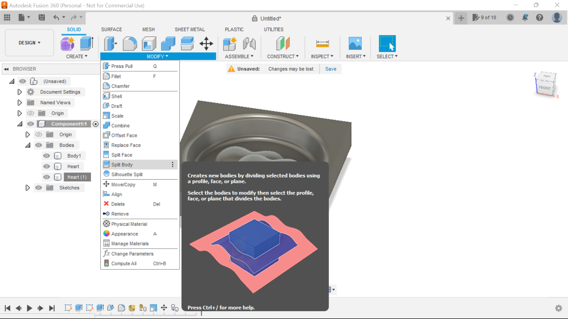
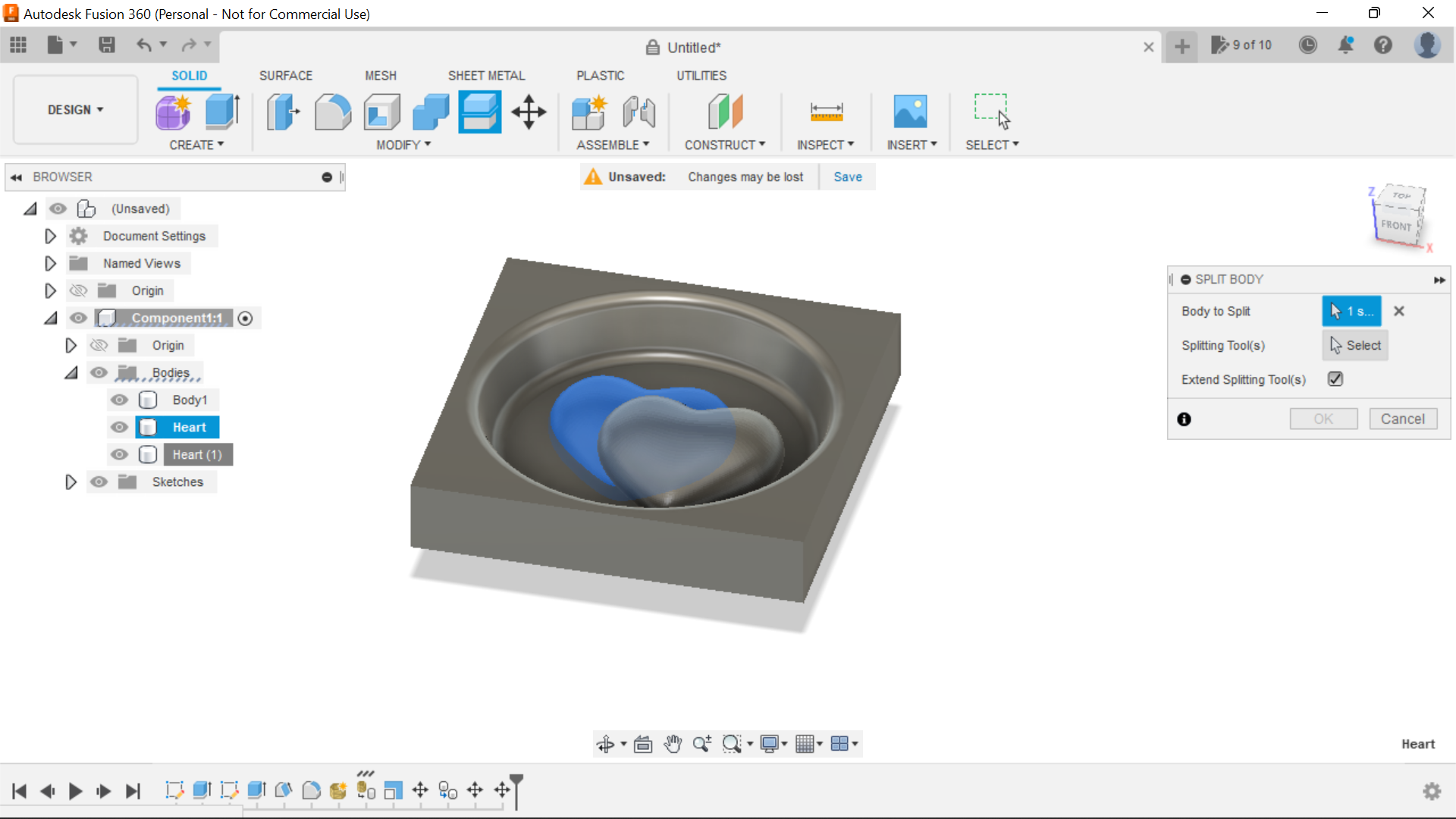
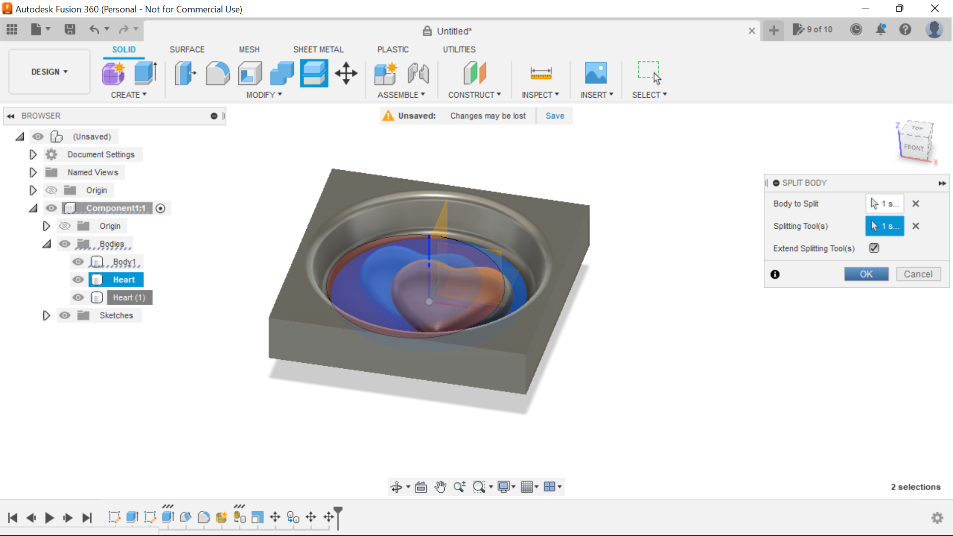
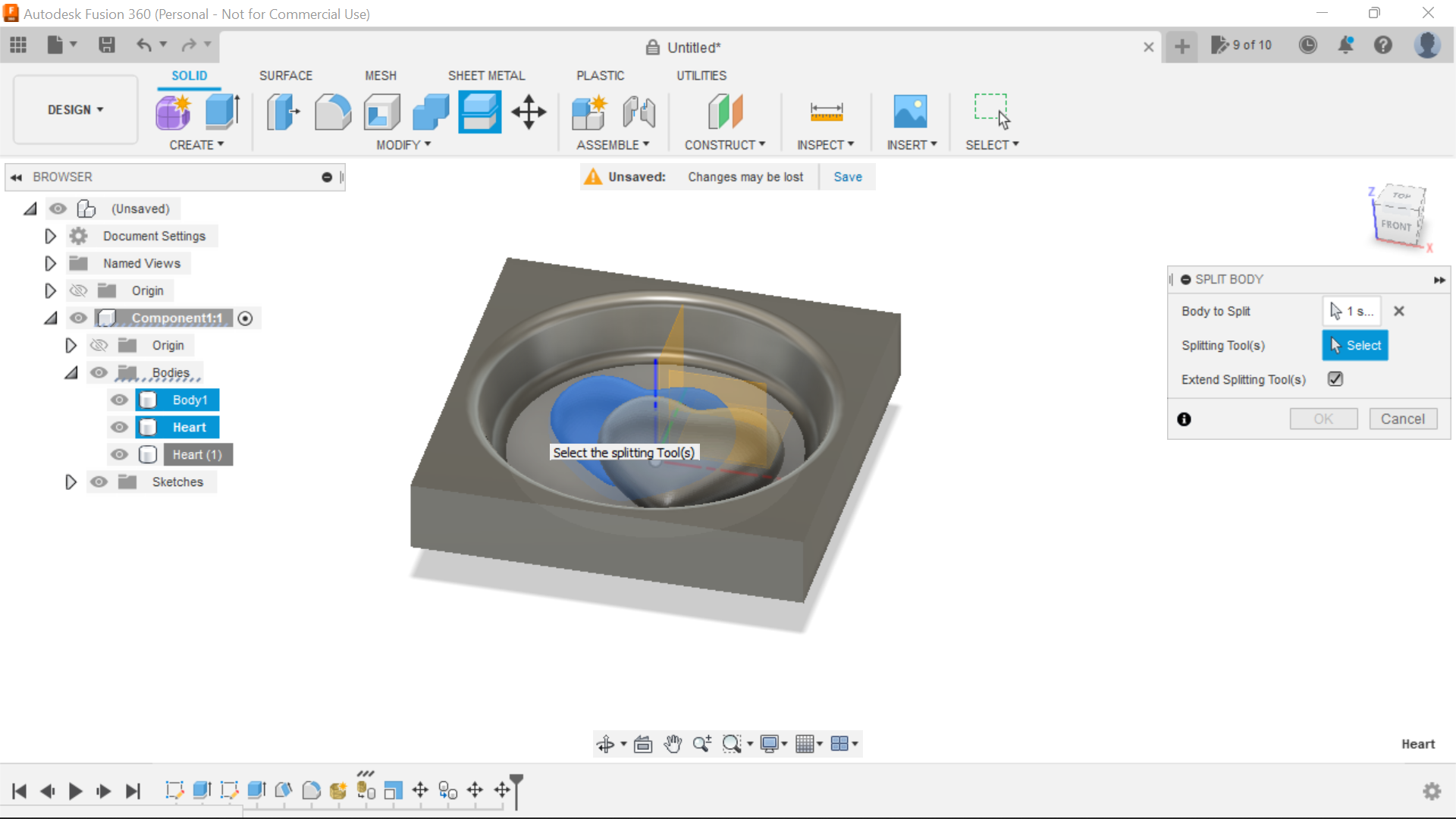
Once happy with positioning we can now move onto splitting the bodies, in the Browser select the 1st heart and then click the split body tab, the Heart is the body to be split, and the bottom of the cavity is the splitting tool, what you end up with is another body in the browser the top and bottom sections, you can turn the unwanted part of the body off in the browser, do the same procedure with the 2nd Heart.
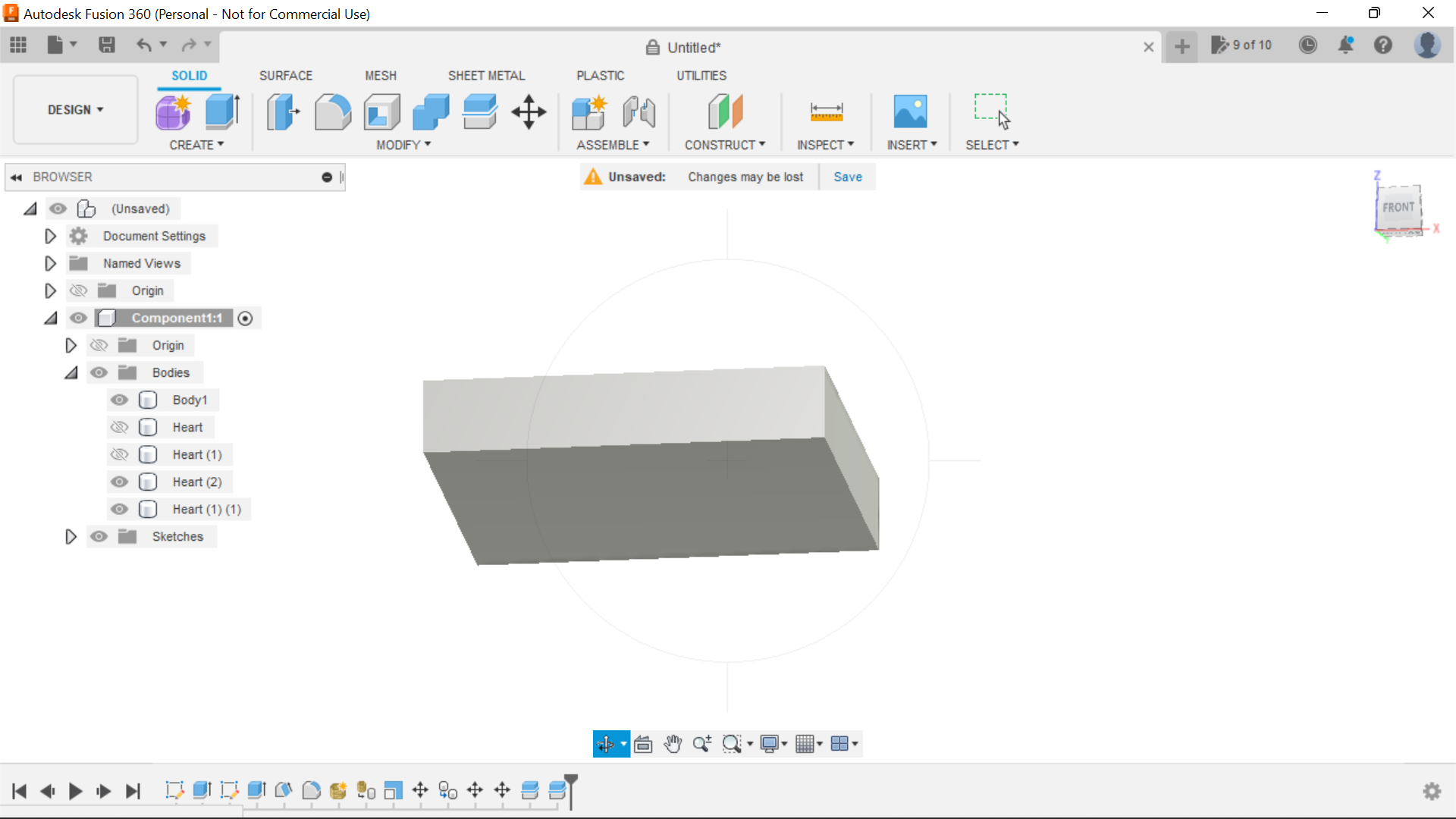
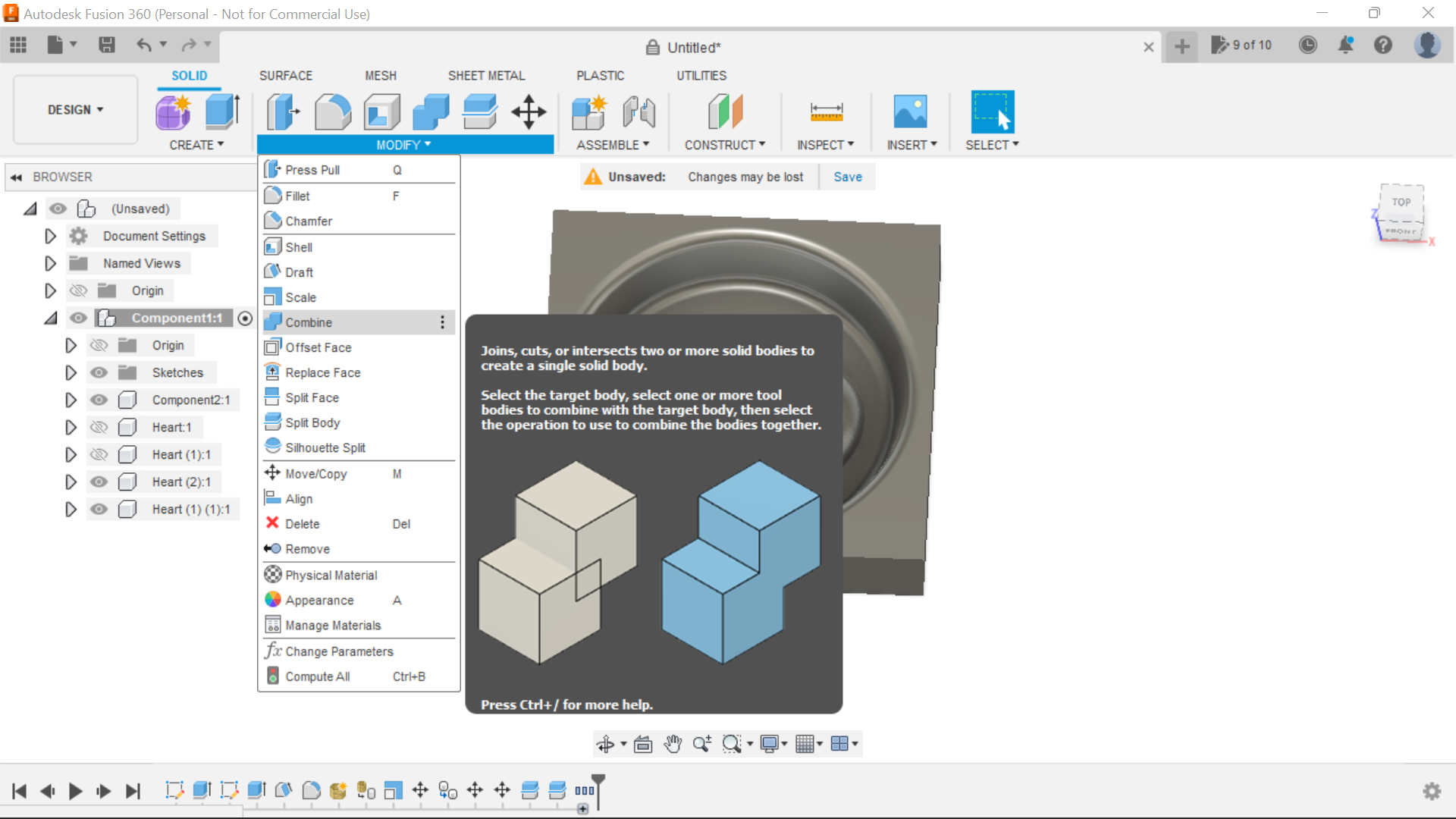
The final part in the design stage is to combine all 3 Components to make one component for the Manufacturing stage.
To do this, Select combine from the drop down box in Modify and click on all 3 components, they will turn blue, then press ok.
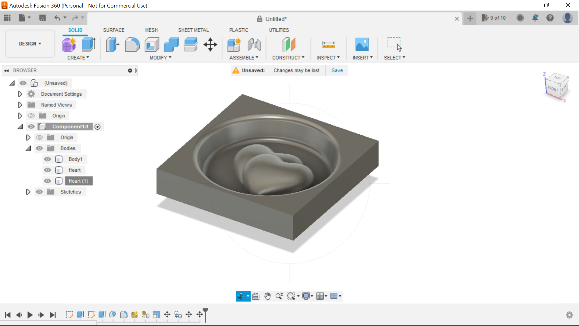
We now have a Component to Manufacture:
Creating a Toolpath
.png)
.png)
.png)
.png)
.png)
.png)
.png)
.png)
.png)
.png)
.png)
.png)
.png)
.png)
.png)
.png)
.png)
.png)
.png)
.png)
.png)
.png)
.png)
.png)
.png)
.png)
.png)
.png)
.png)
.png)
.png)
.png)
.png)
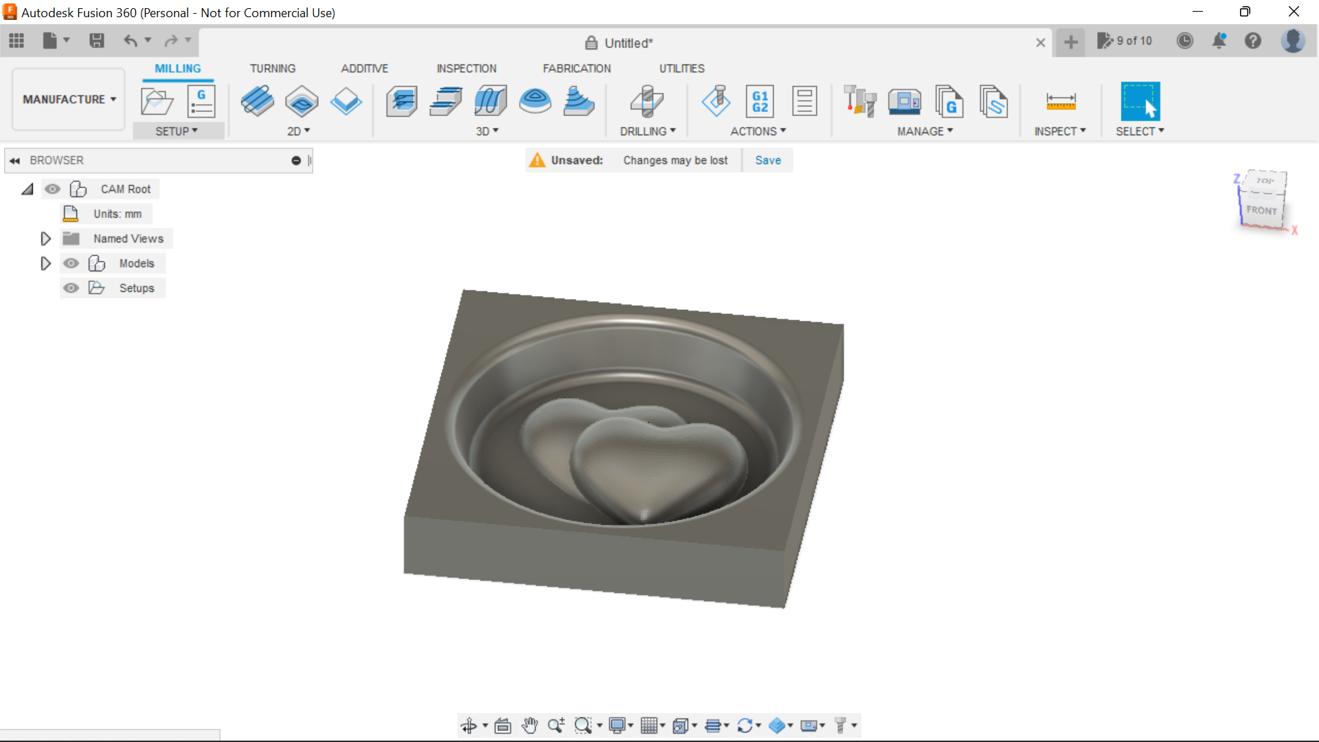
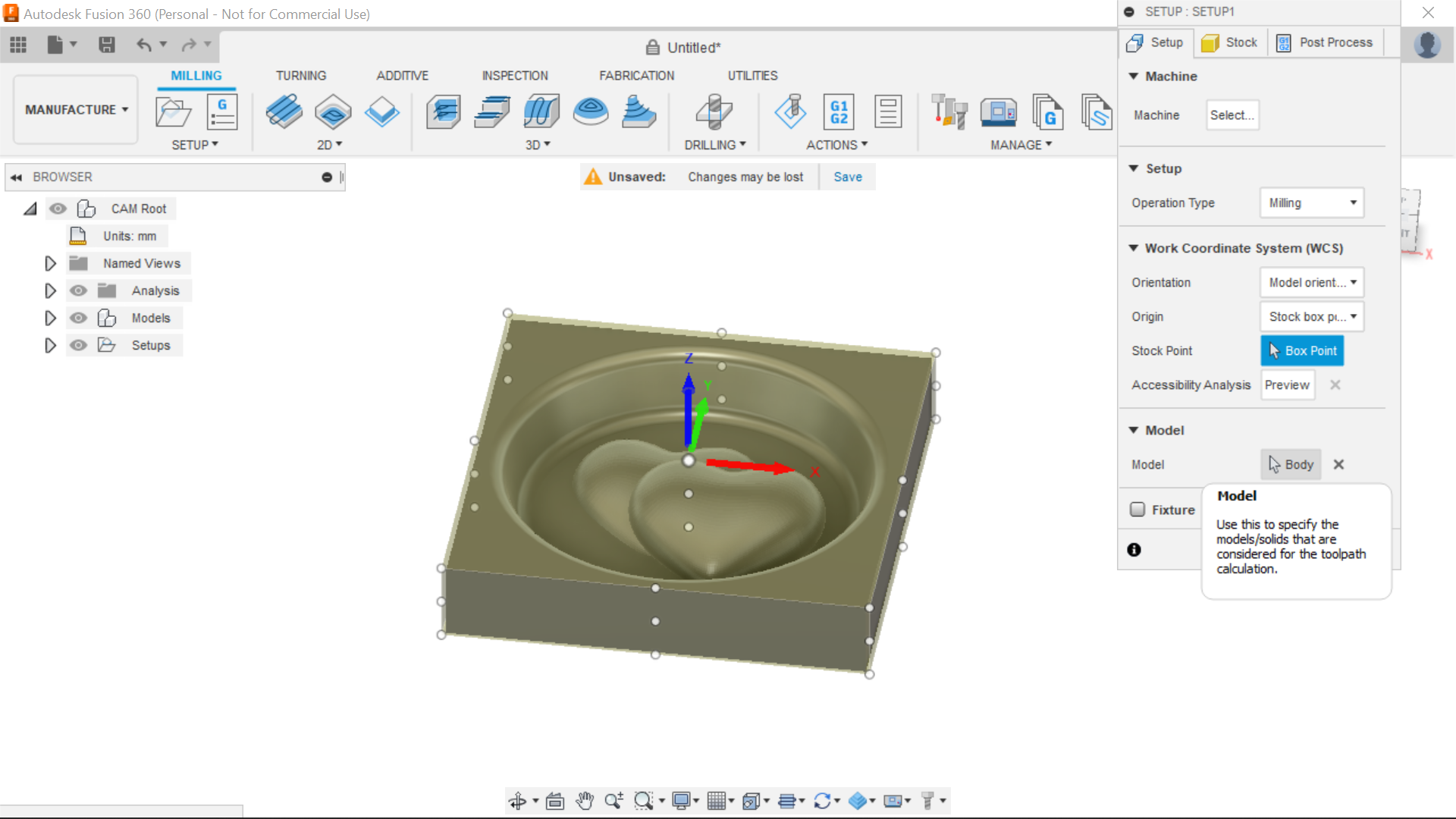
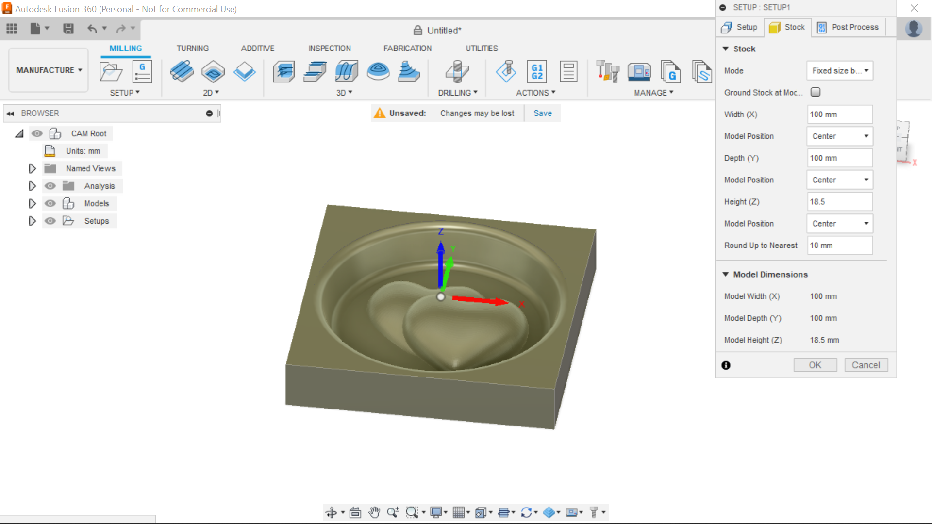
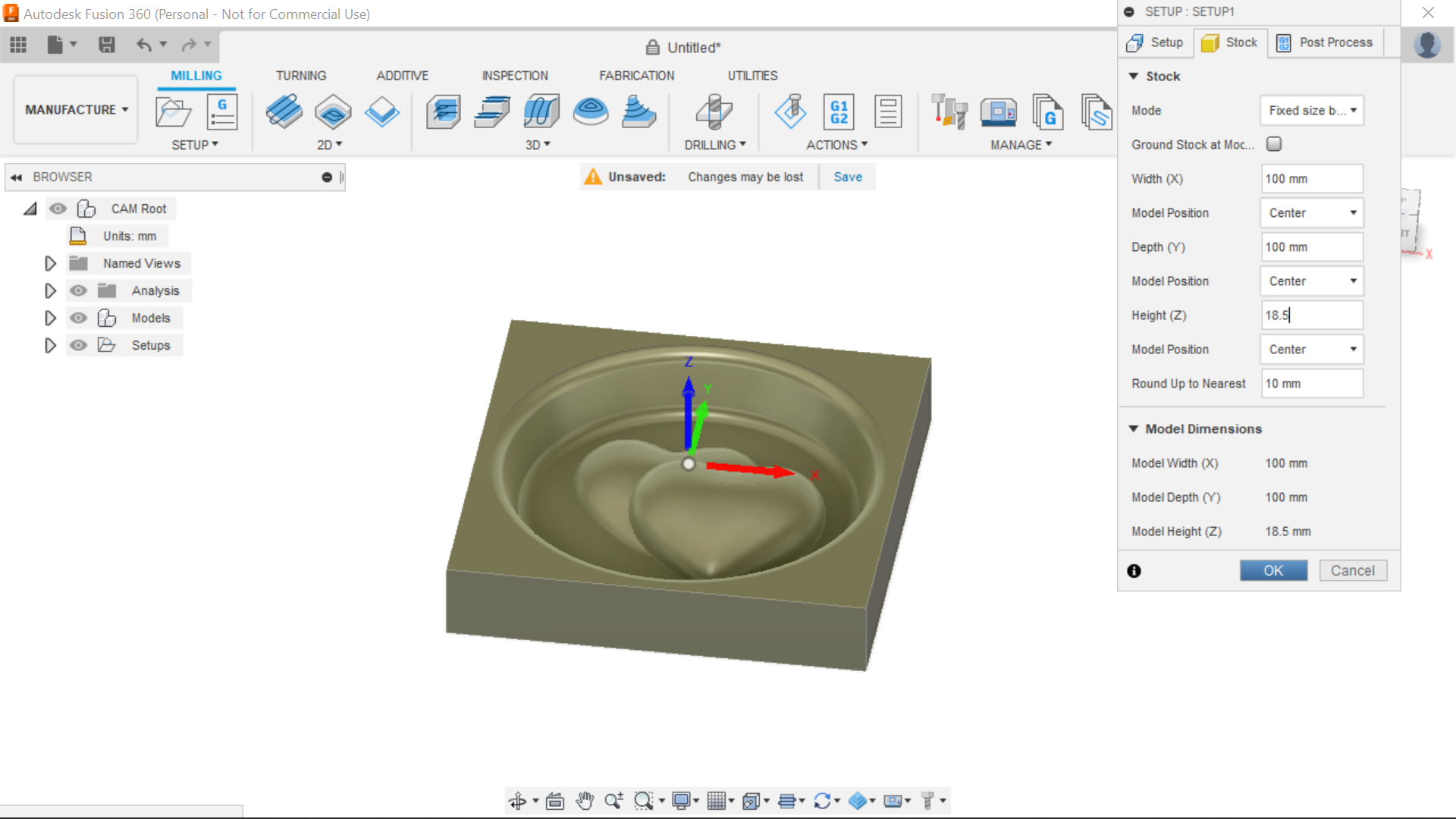
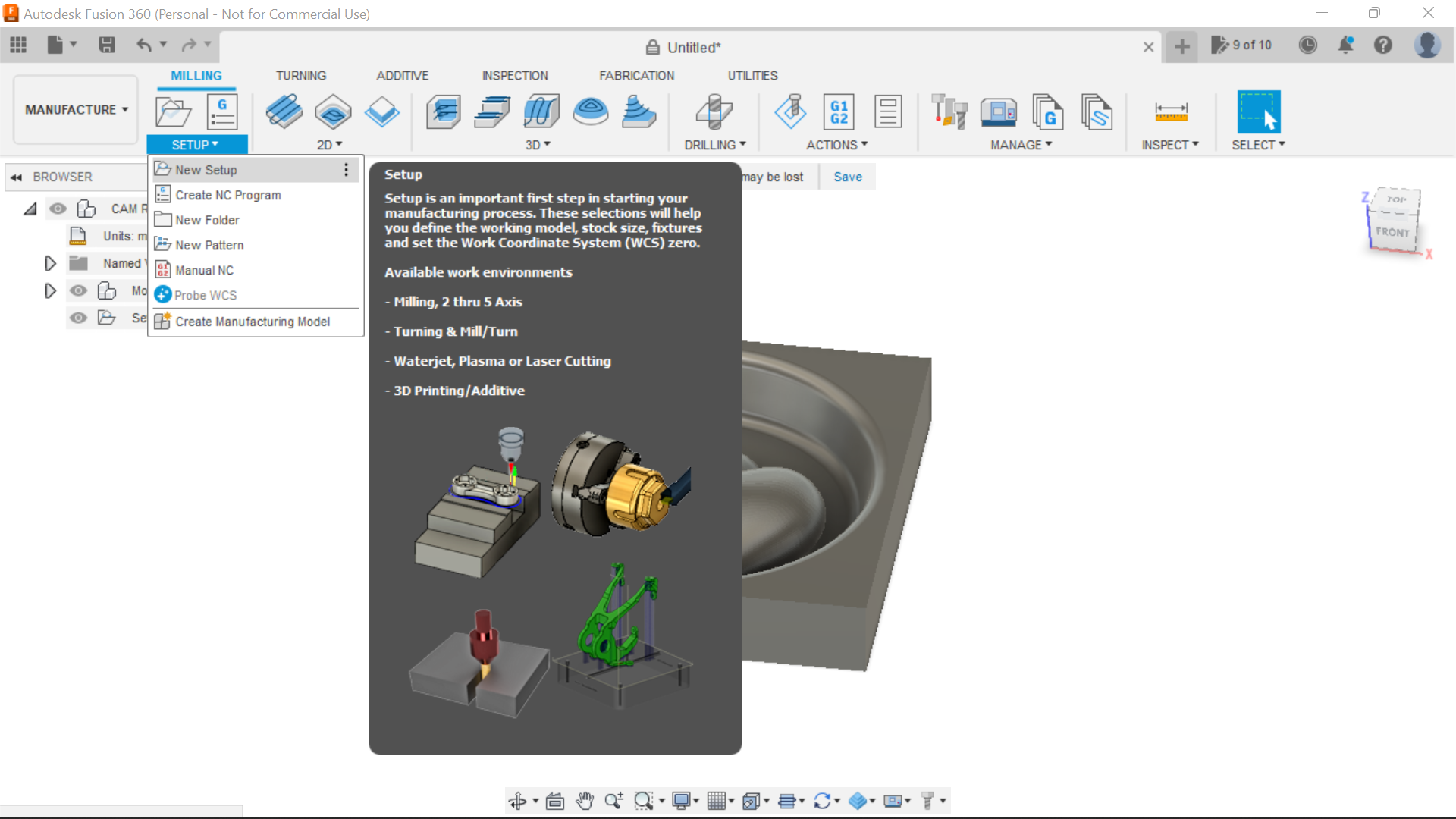
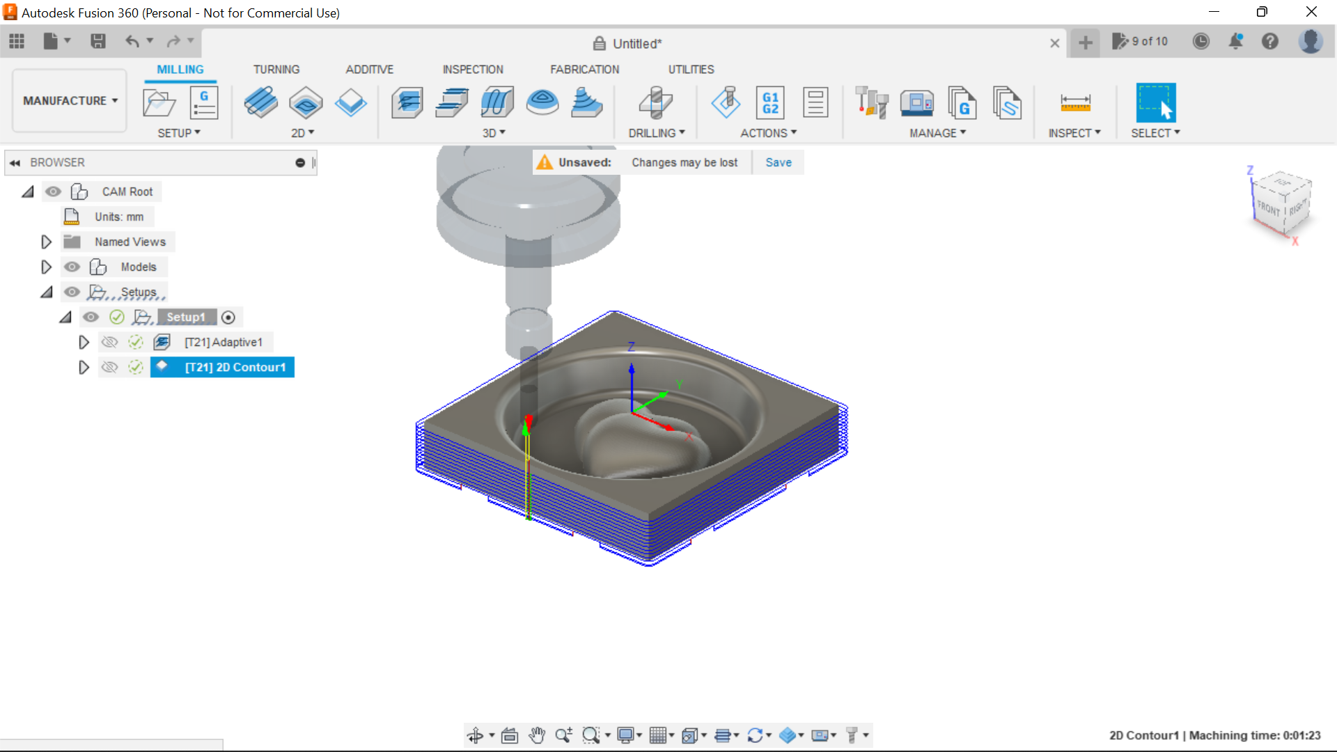
Selecting the Manufacturing Tab we can select new Set up, from here we can select the position on the stock where we want to start from, I'm opting for the centre of the stock, You can select the body to be cut and the design will turn blue, on the next Tab I select fixed size box and no offsets needed as the stock is the correct size thickness etc, I changed where it said 20mm thickness to 18.5mm.
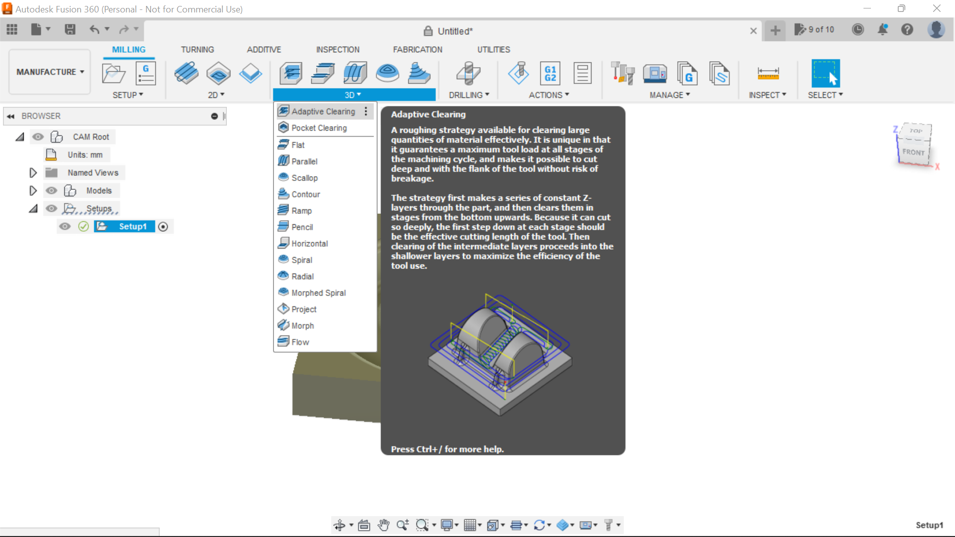
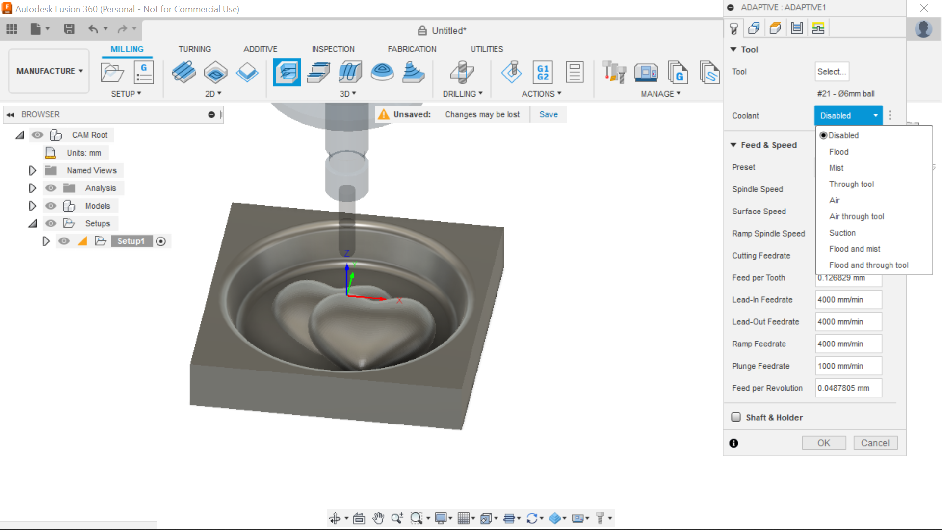
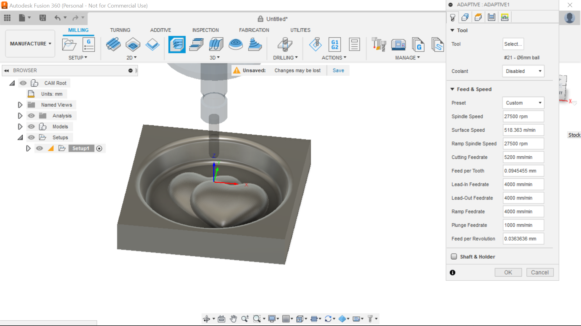
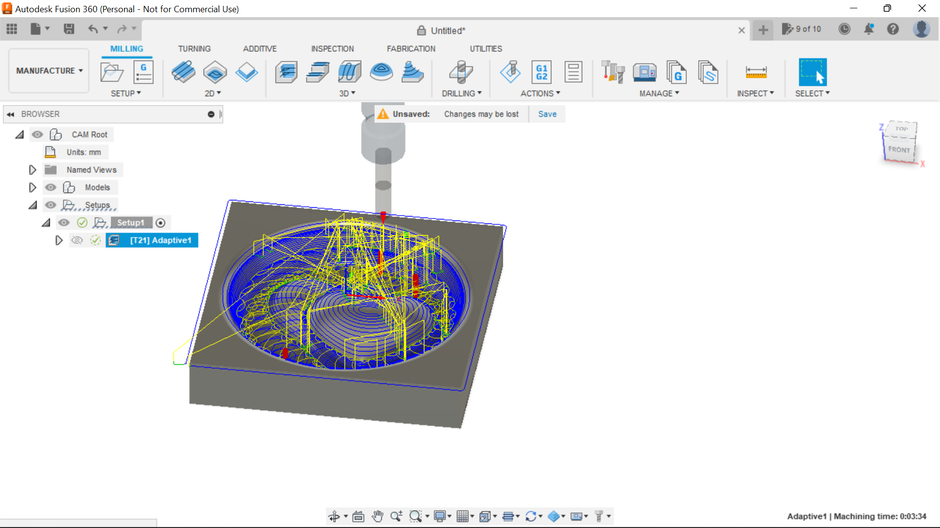
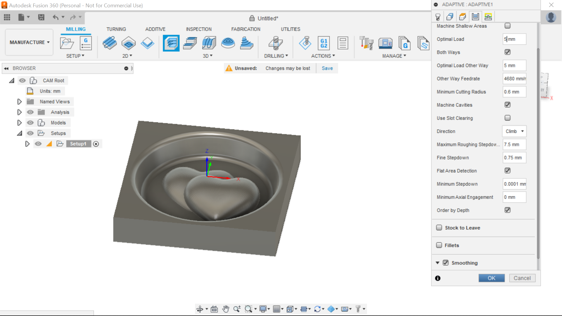
For the next operation I select the 3D adaptive clearing, and to be really honest I don't change very much in this section,
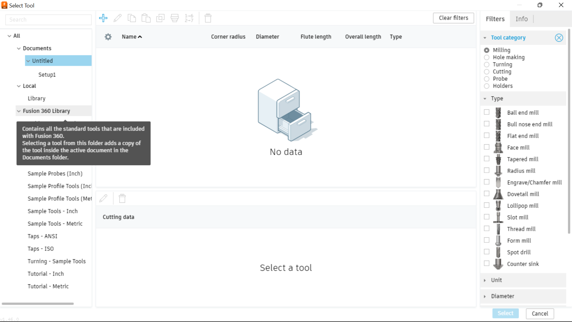
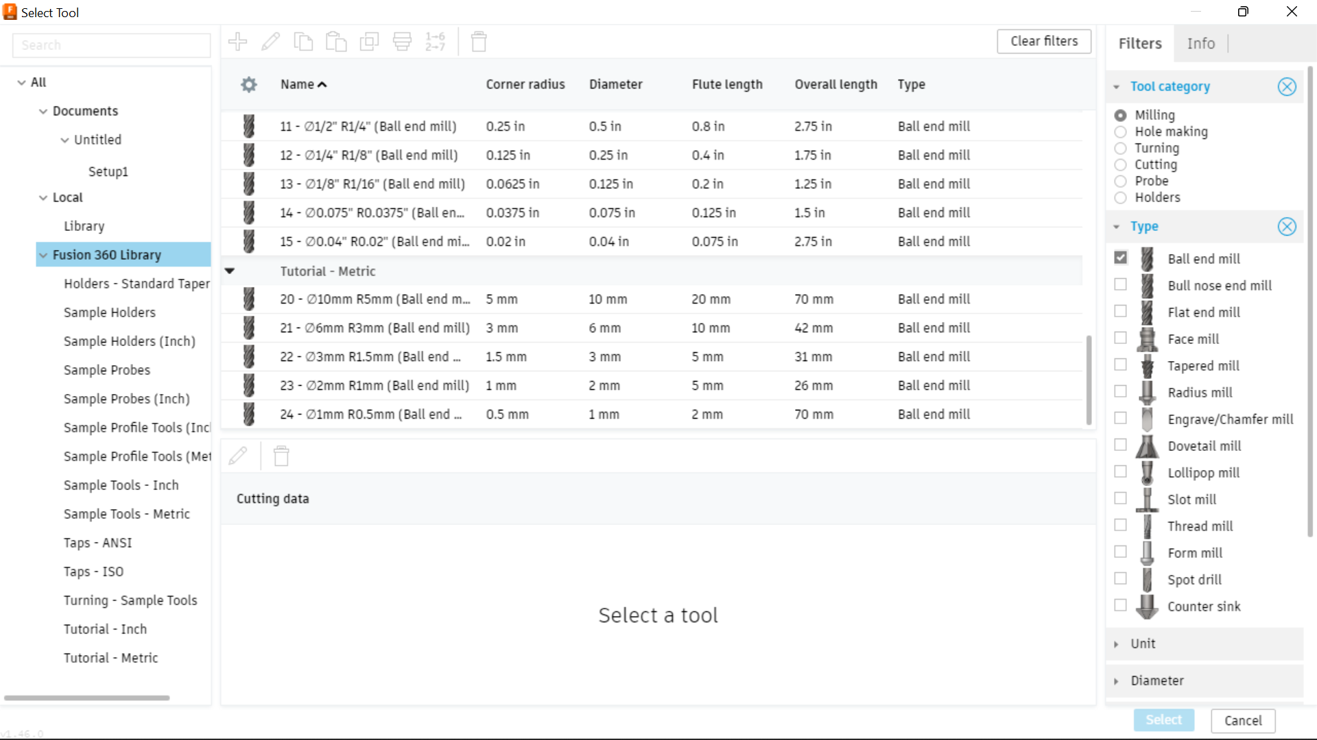
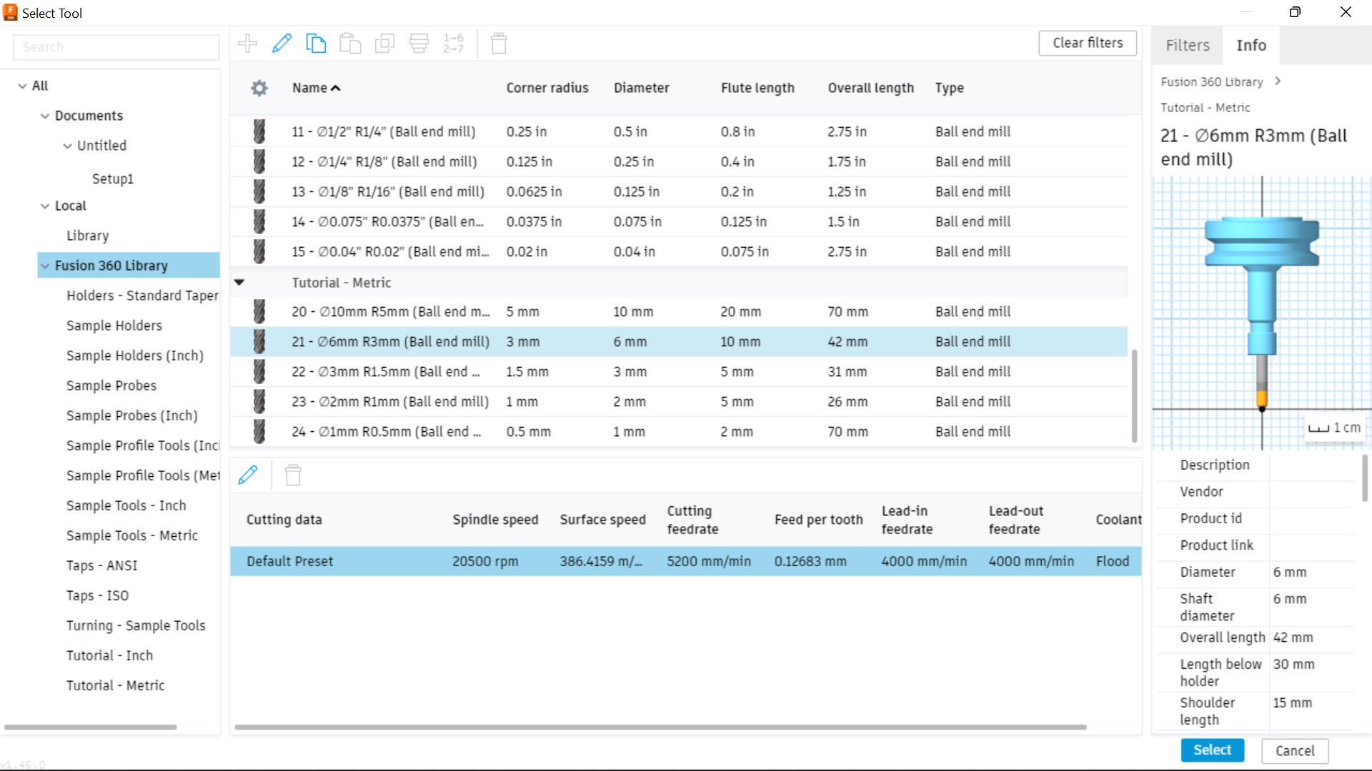
This section has a number of tabs, the first being Bit size and coolant etc, clicking on tooling takes you to the Tool library, Look at the screenshots rather than me trying to explain, I have created many screen shots highlighting the different tabs and the procedures within them, but briefly, I select a 6mm Ball End Bit, Disable the coolant but not important anyway as I don't have that, I adjust the RPM for my router which full on is 27500RPM Cutting feed rates amend automatically.
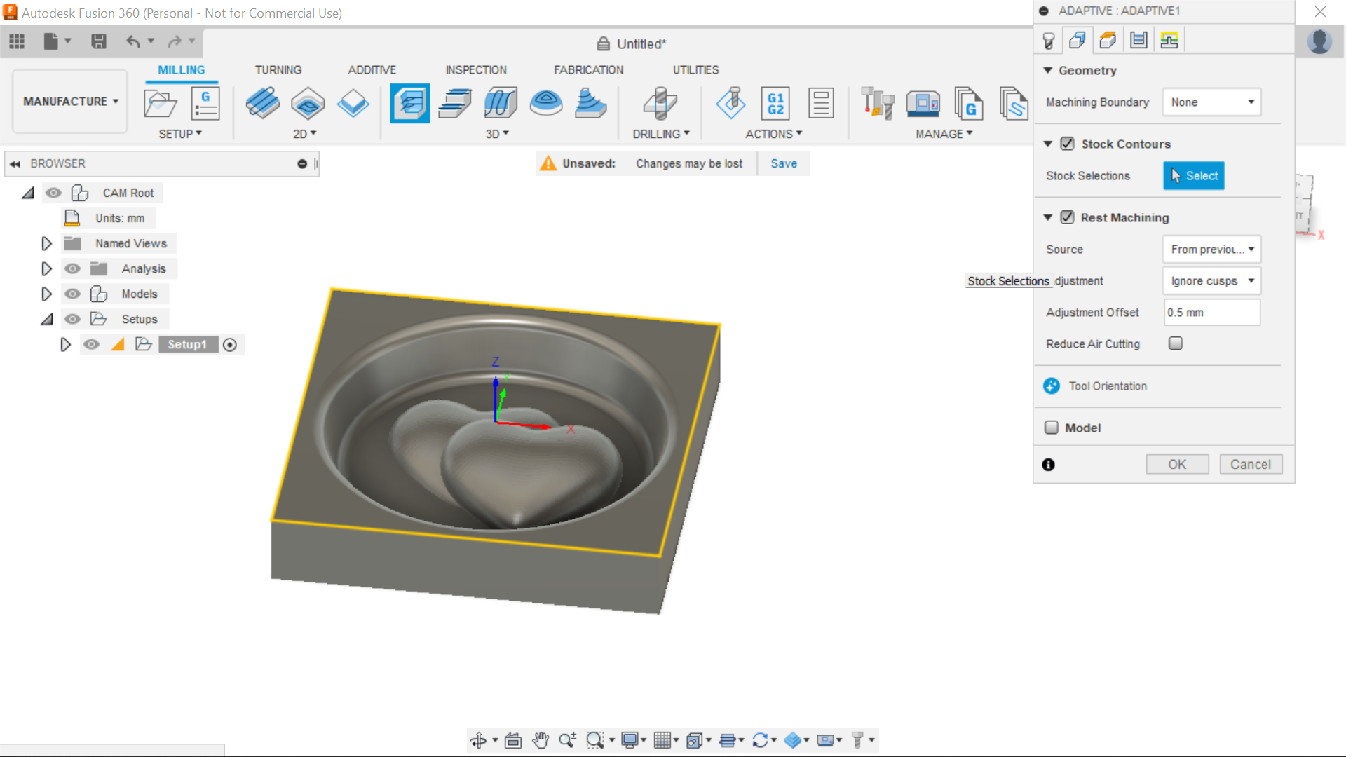
Next Tab is Geometry, I don't touch anything in here, Stock Contours is Ticked and so is Rest Machining.
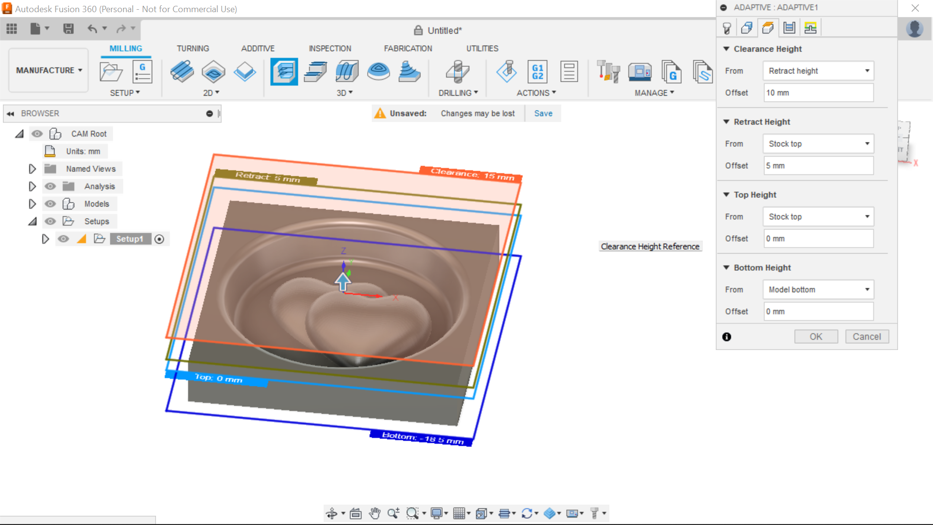
Heights I go with what's already there.
In Passes, Optimal load is set to 5mm, I select Both Ways, Order by Depth, Maximum step down is 1.5mm and Smoothing is ticked.
Pressing ok will start processing the Toolpath, this use to show a percentage of the process, now its another thing, not sure what it is but its to the left of the adaptive clearing tab in the browser, when it's complete, there is a dotted circle with a tick in it.
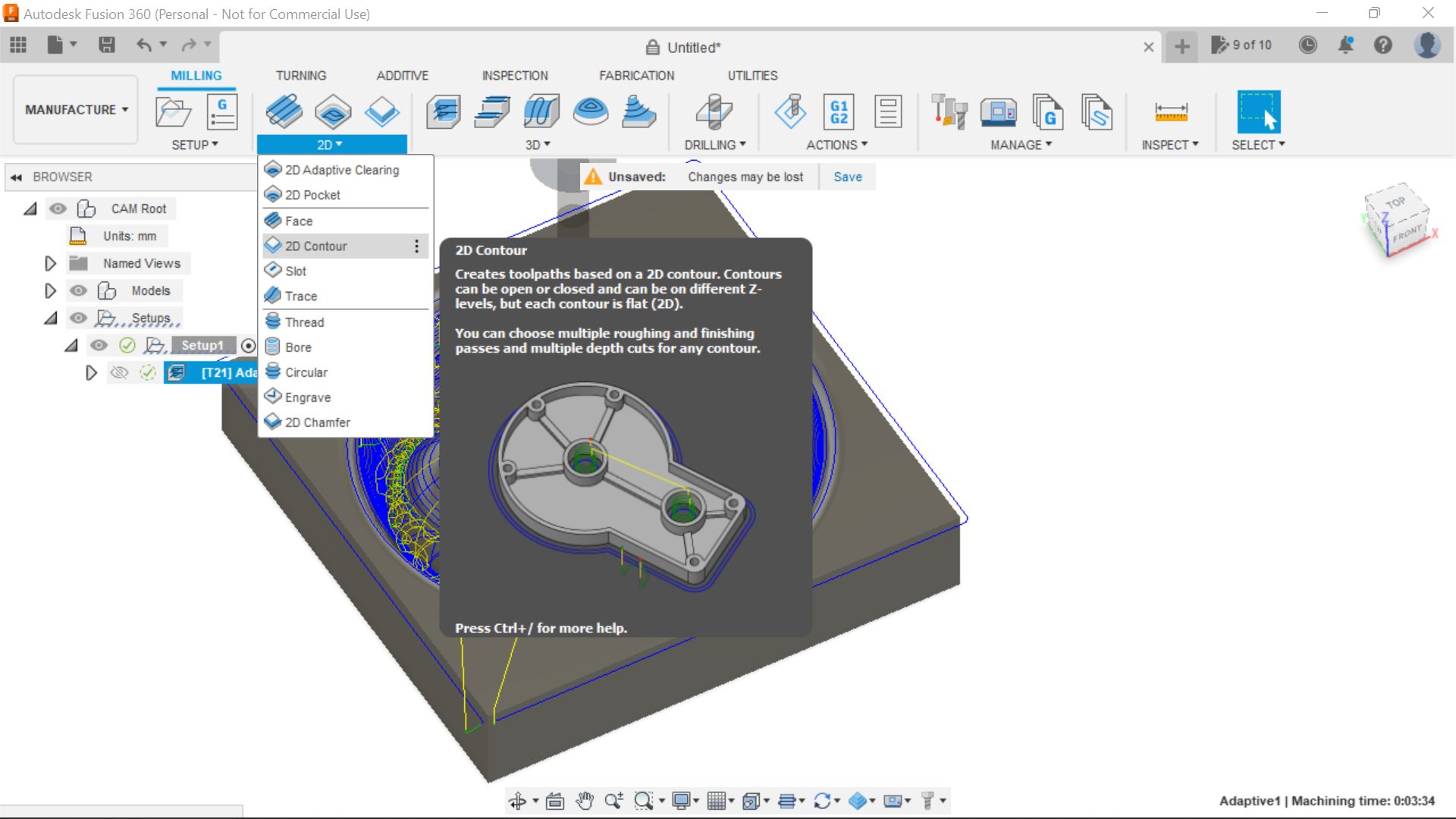
The Contour tab is used to cut the piece out of the stock, although I clicked on Fixed size box I can still use a bigger piece of wood as I'm starting from the middle of the piece, A bigger piece of stock can be used as you need to screw it to the waste board or use clamps etc.
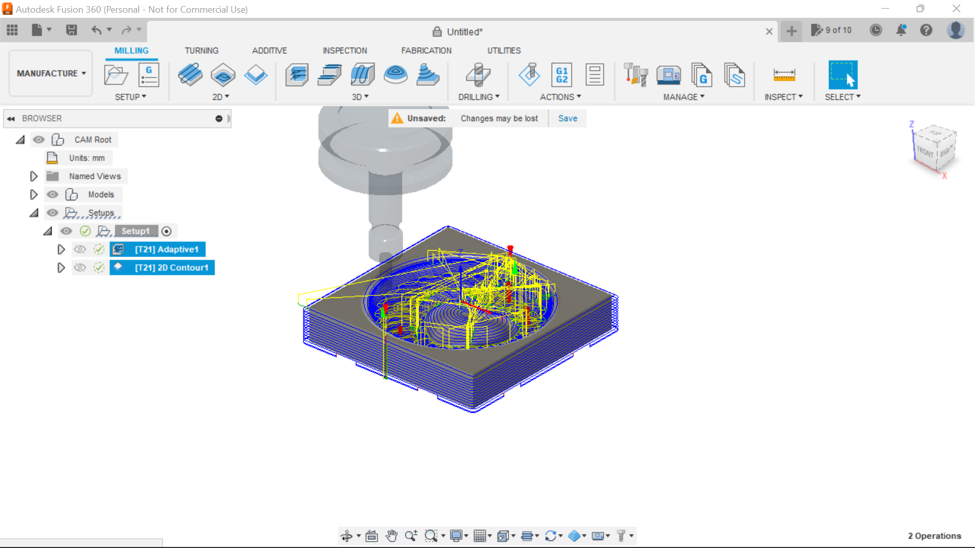
All the data is still there from the Adaptive clearance toolpath, not best practice but I'm using the same 6mm Ball end bit to cut the piece out, just highlight both the Adaptive clearing tab and the contour tab when its time to post the toolpaths, Adaptive first and contour 2nd.
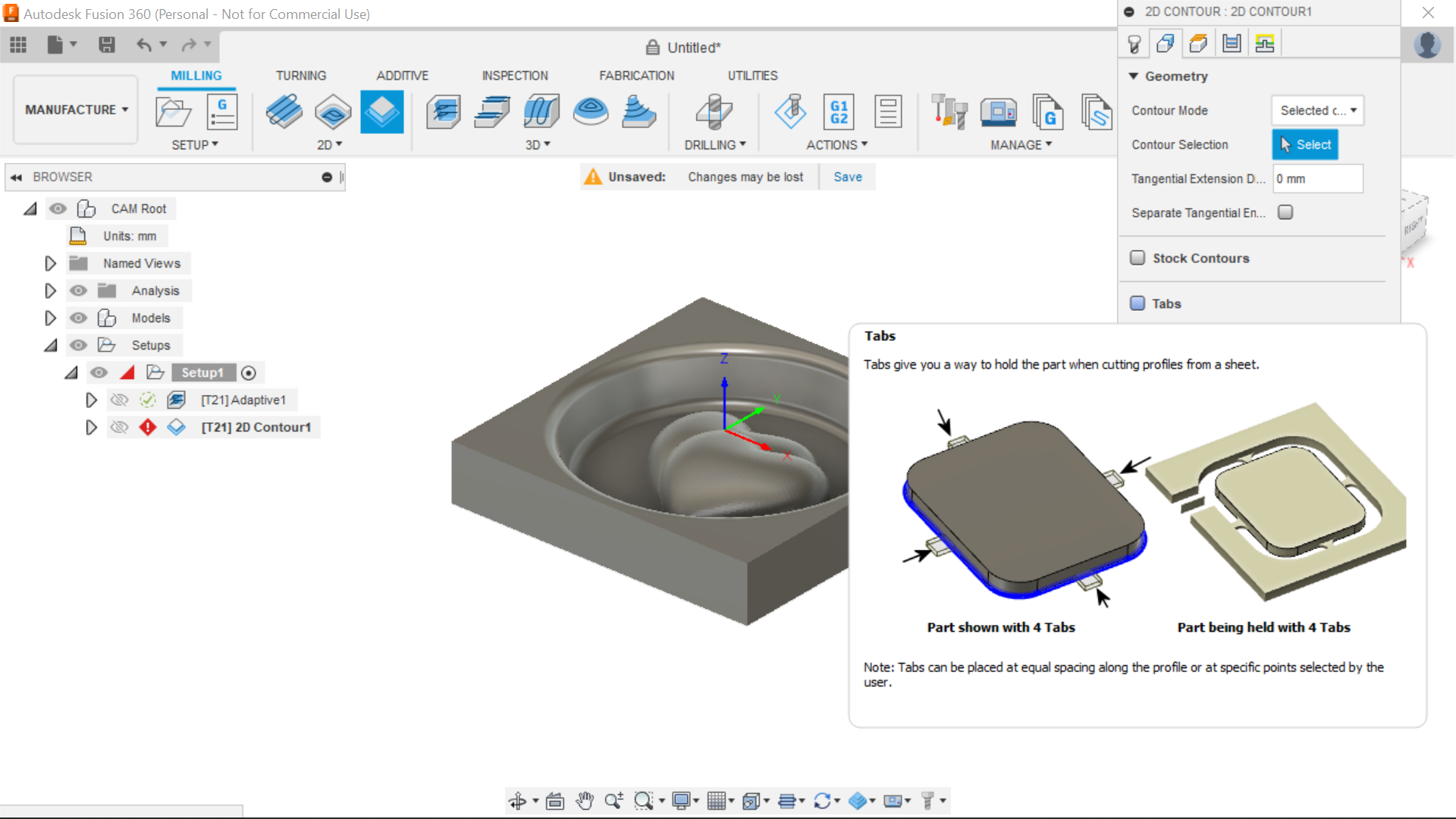
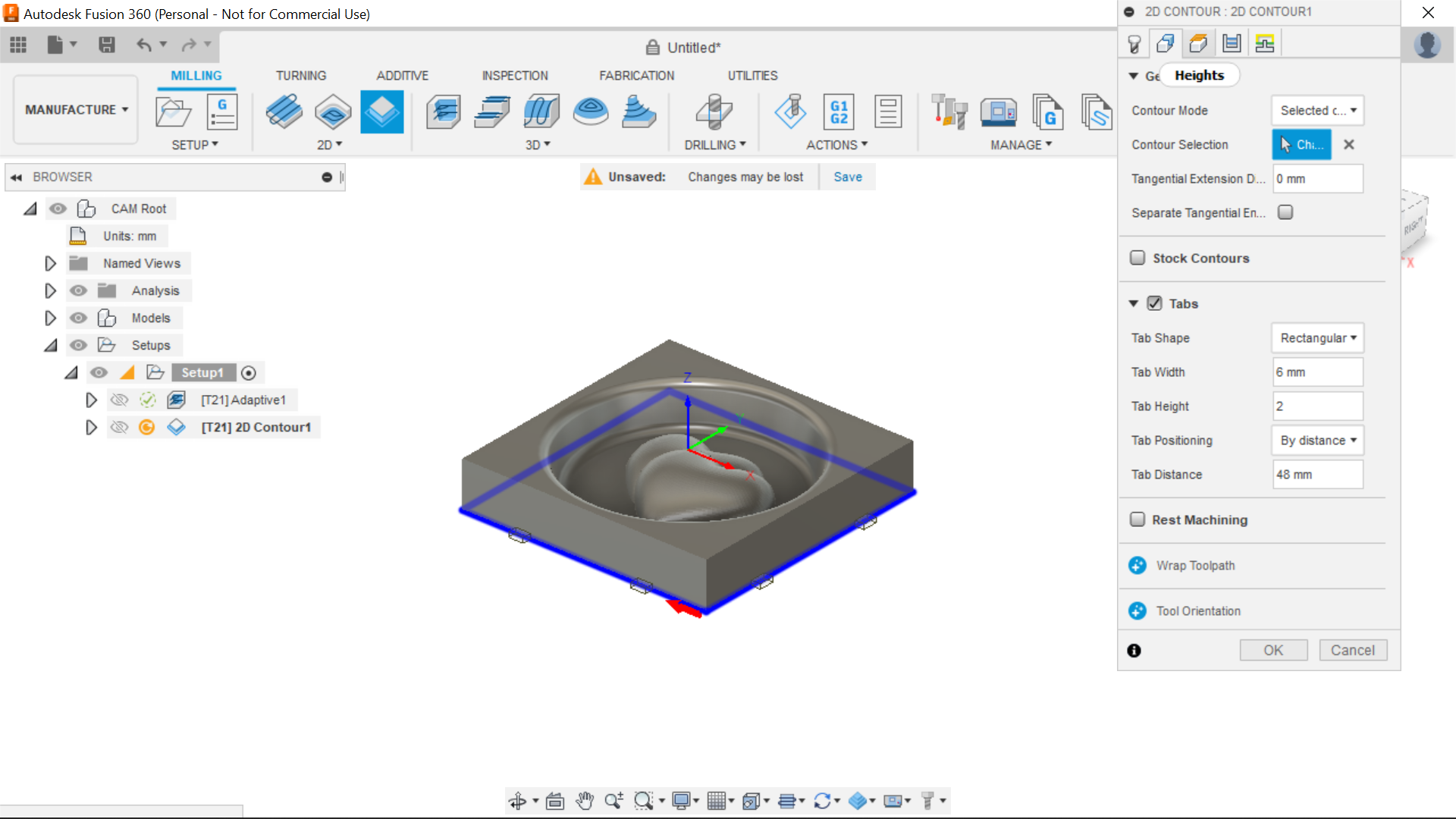
In the Geometry section, Tabs are added to hold the Piece in place after cutting, set this to what size Tabs you want,
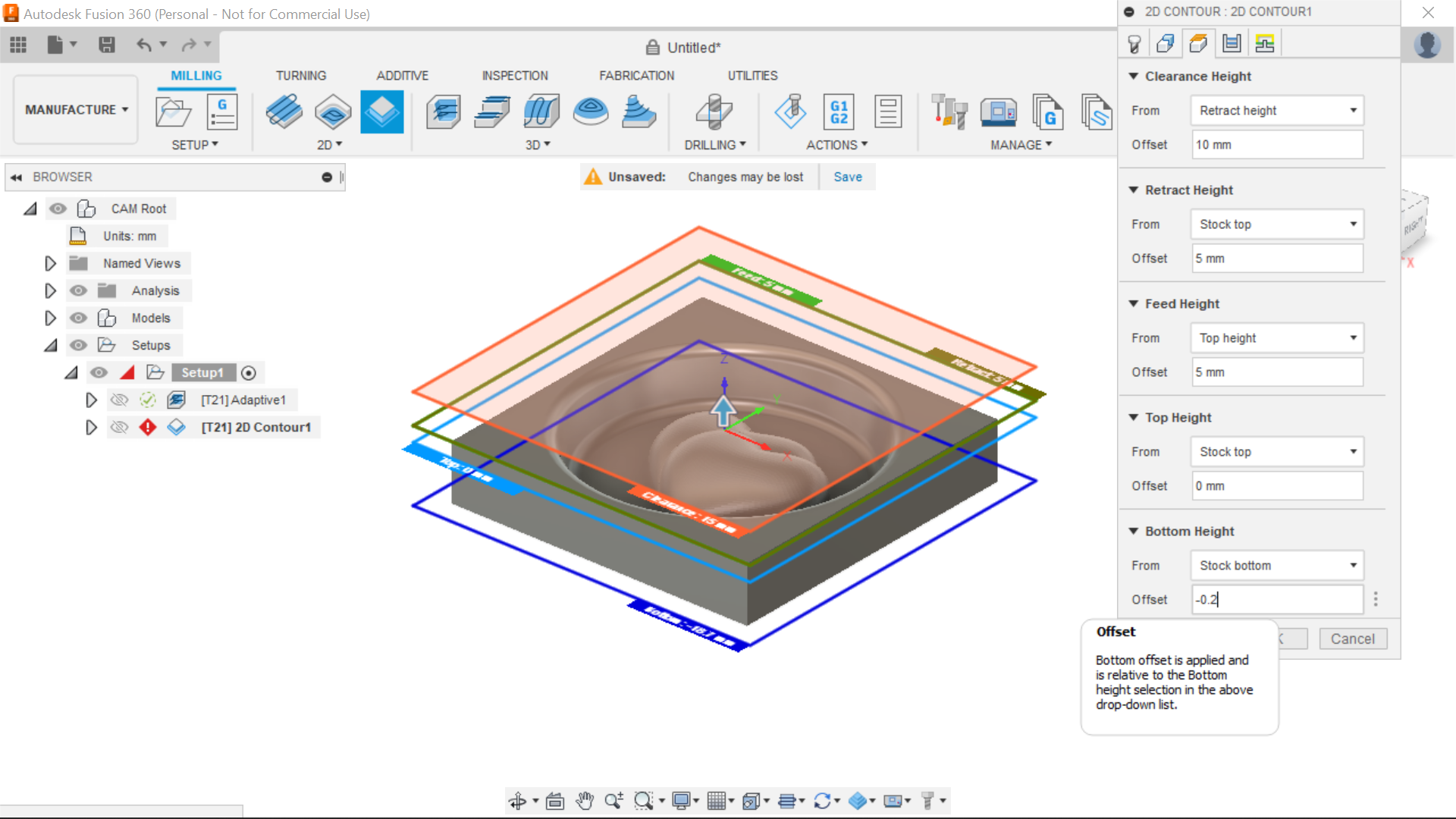
Clearance Height, In the Clearance Height section, where it says Bottom Height, next to "From" there is a drop down box. I select from Stock Bottom and Input a depth of -0.2mm so it will cut all way through the piece and just leave the Tabs.
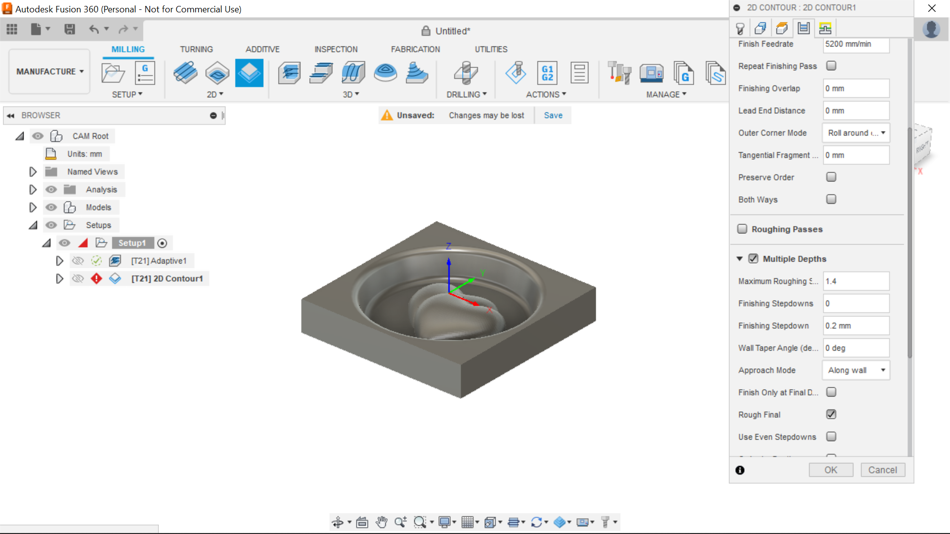
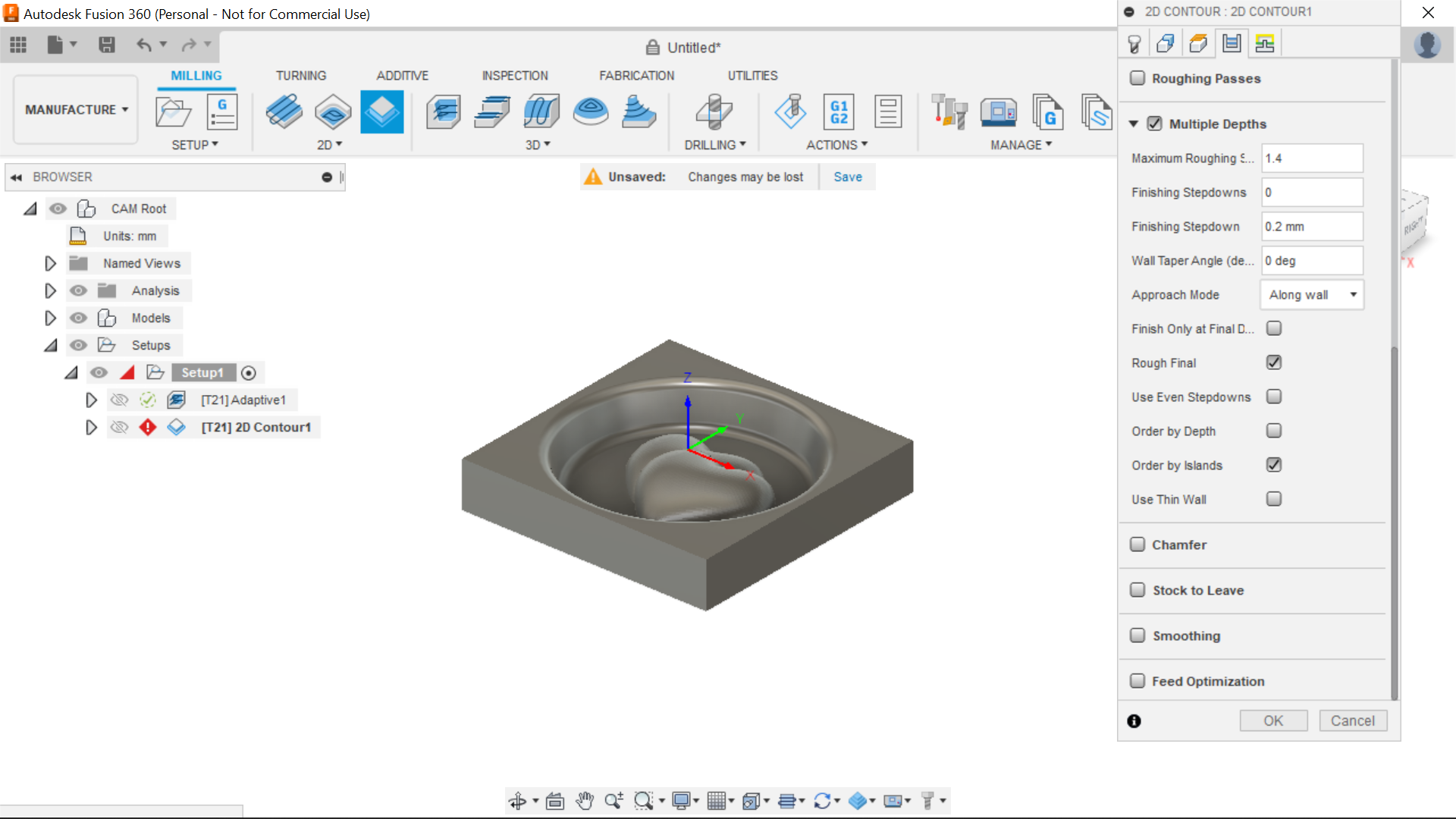
Passes section is Multiple Depths ticked and Maximum roughing 1.4mm and finishing stepdown 0.2mm.
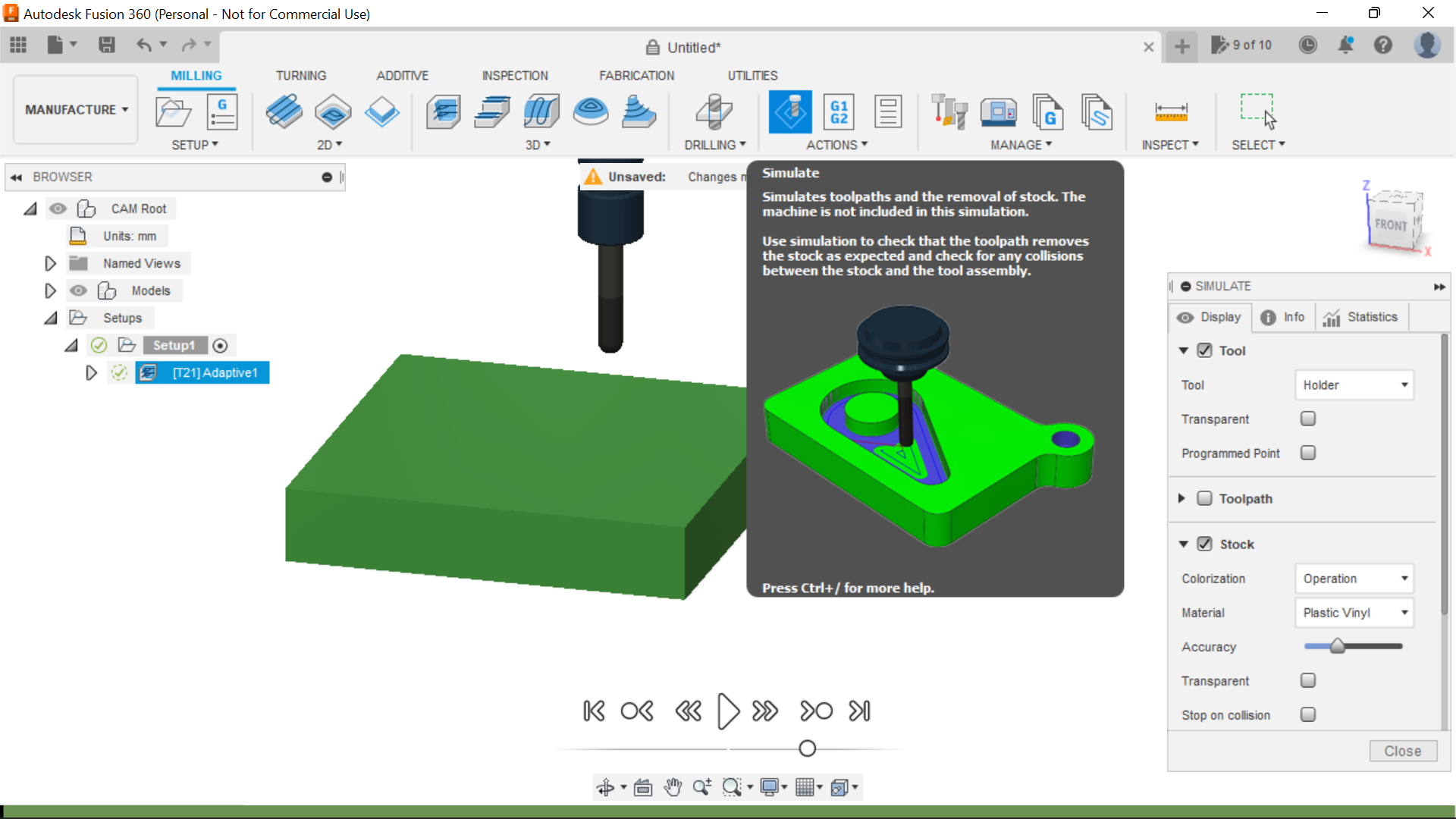
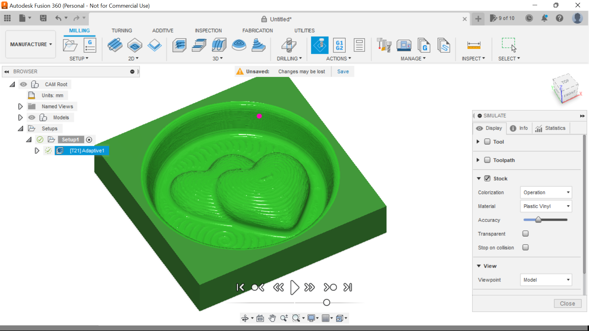
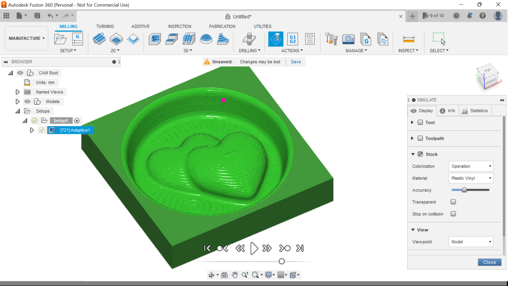
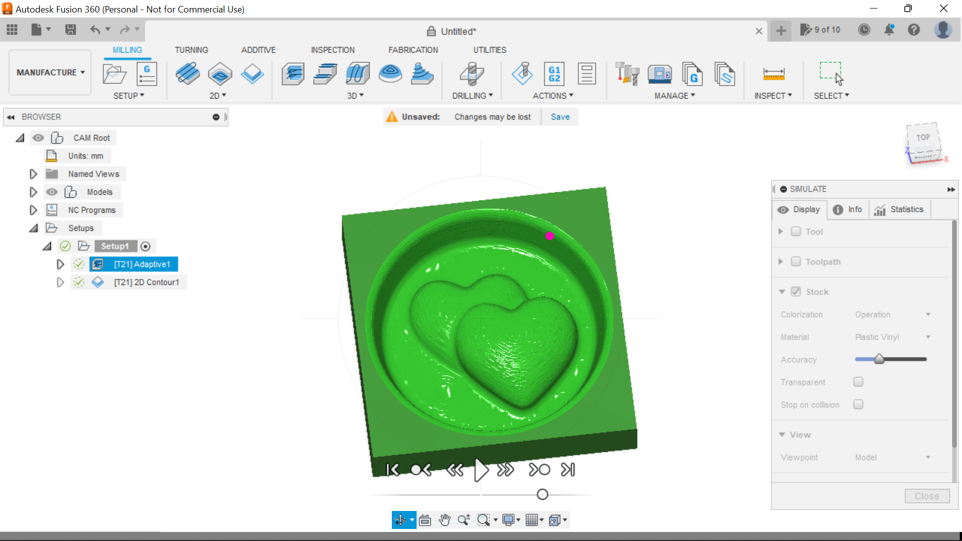
With both the Adaptive Clearing and the Contour Toolpaths we can Simulate the cutting, what I've found is that the Simulation is pretty spot on to the finished piece.
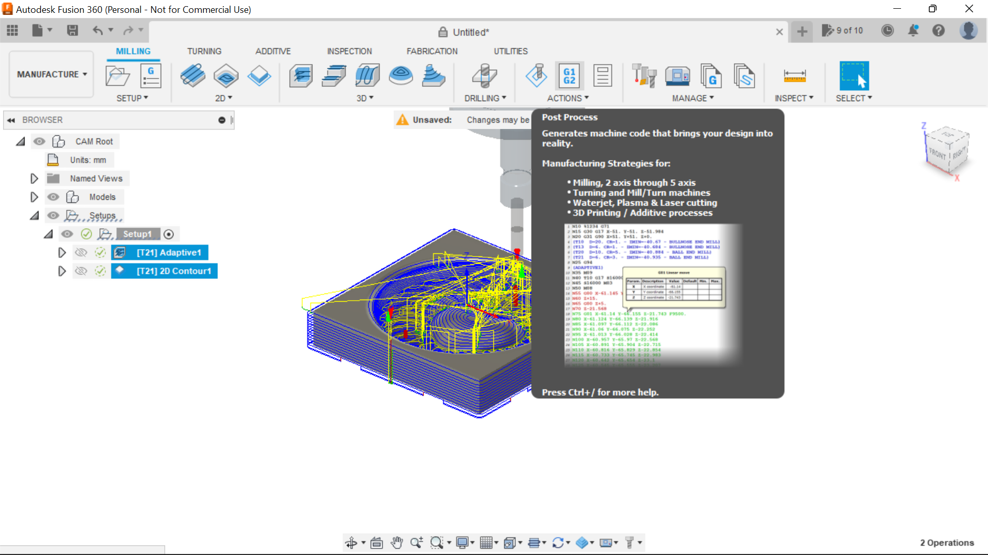
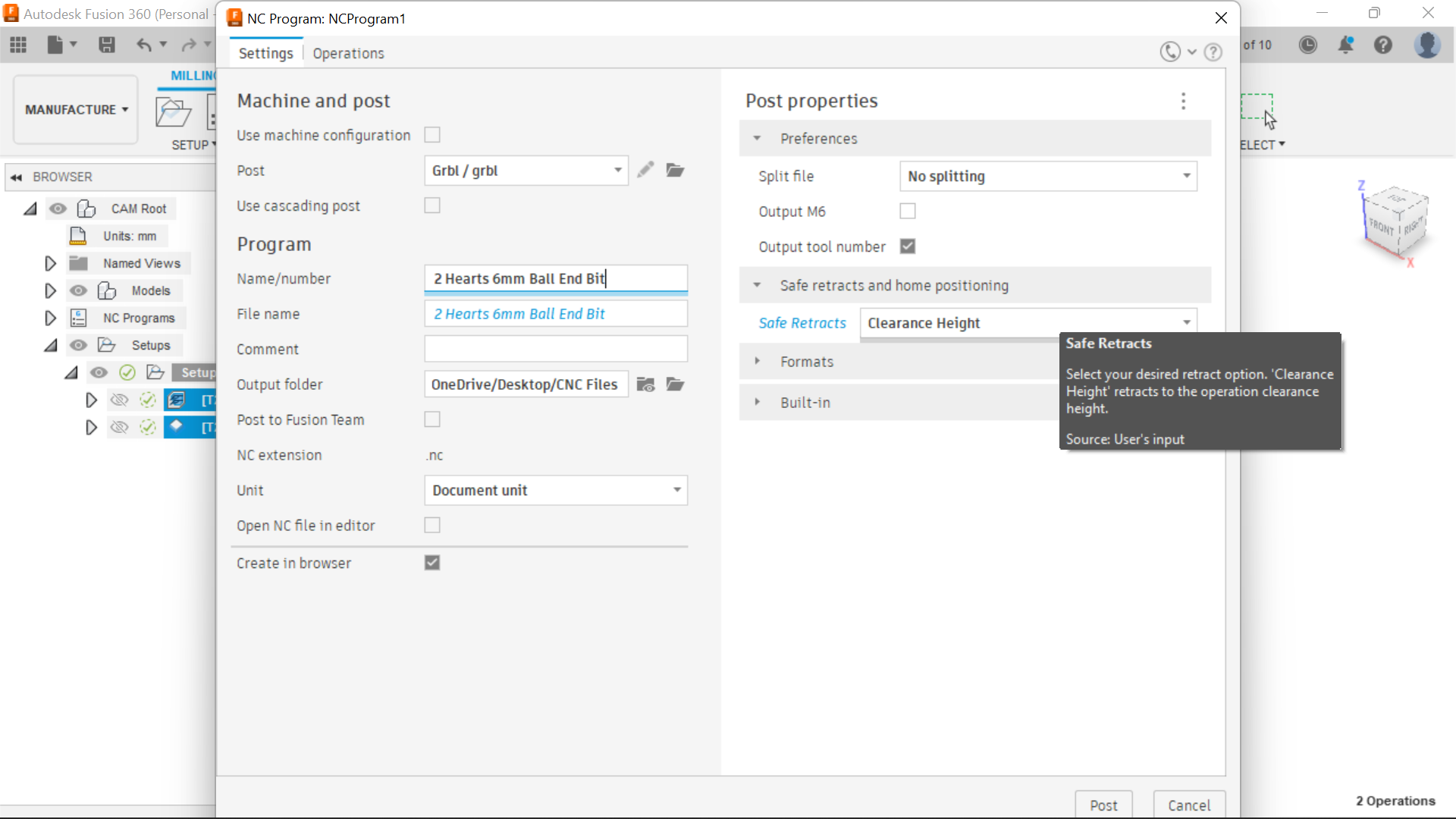
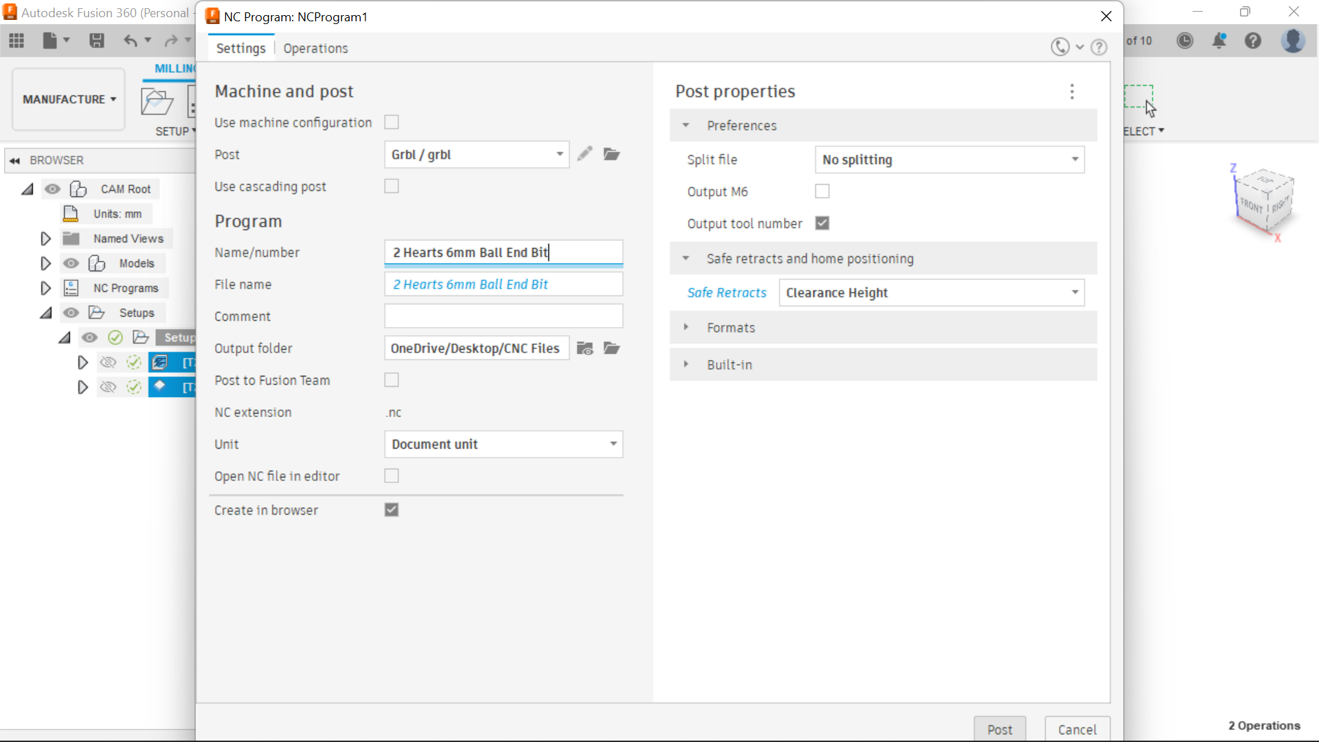
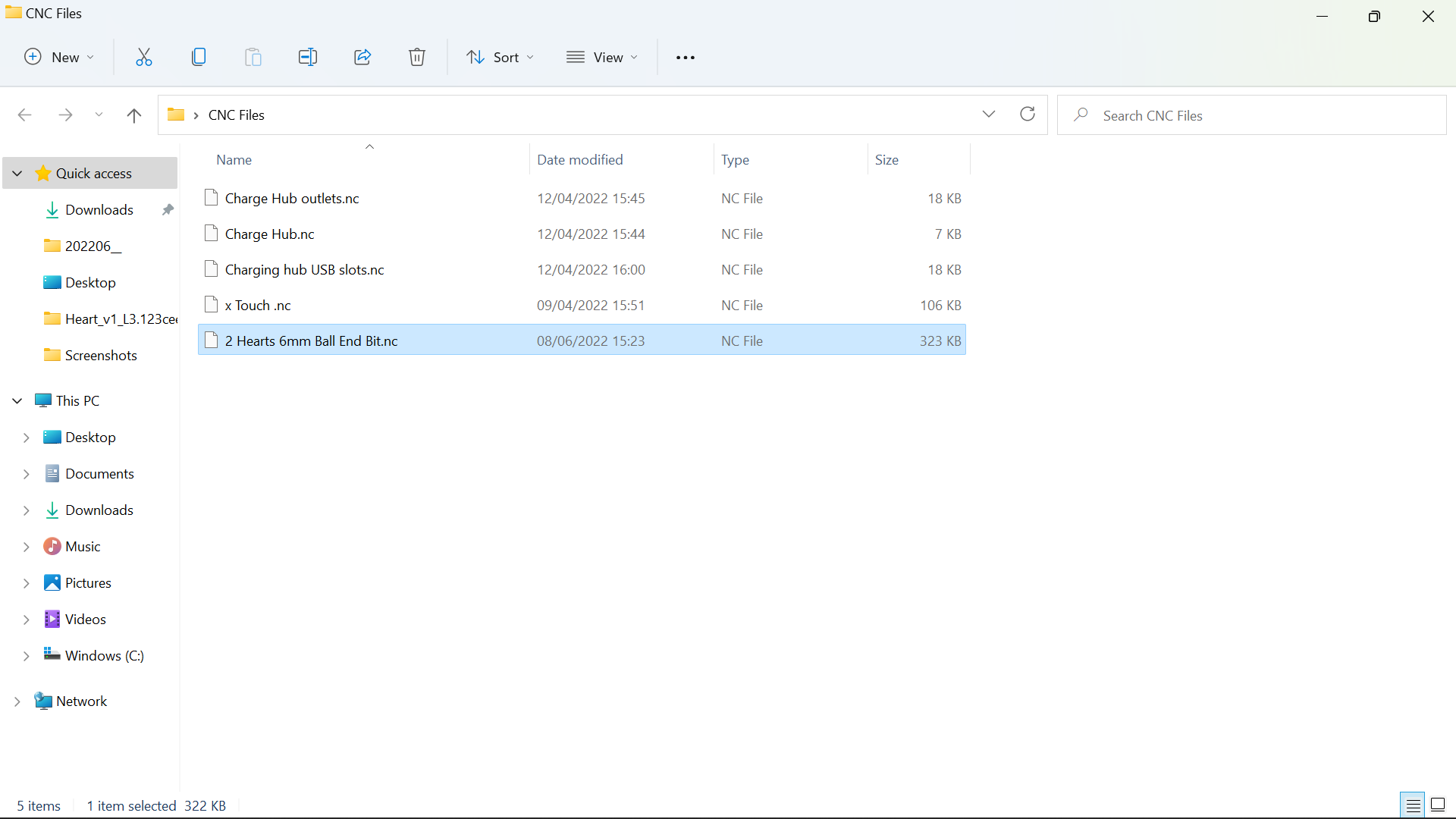
The final process is to save the Toolpaths, Next to the Simulation Tab is the Post Process Tab, press the G1G2 button, here we can name the Toolpath and also Select the output folder, I have a CNC folder in Desktop and the files are sent to that, In the section to the right of the page where it say's Safe Retracts, I select clearance height, then when I set the zero on the workpiece, I raise the bit up to fit the Dust shoe and I don't return to zero, doing it this way the router moves to the starting position before moving the Z axis down to start cutting, when I've selected Return to Zero, the bit moves across the top of the workpiece, I've had damage before I've started really, anyway that's what works for me.
Onto the cutting process:
Downloads
The Cutting Operation.
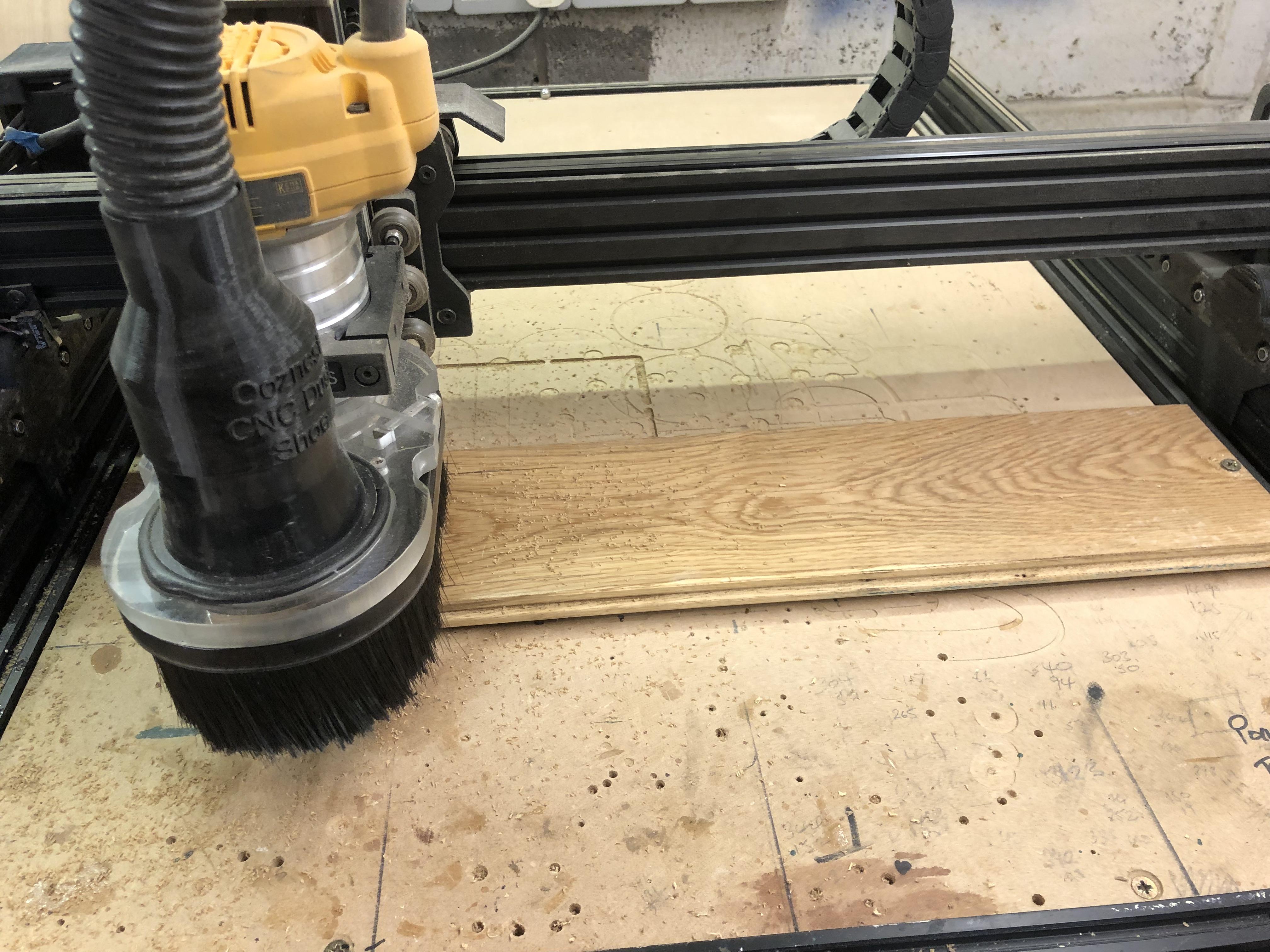
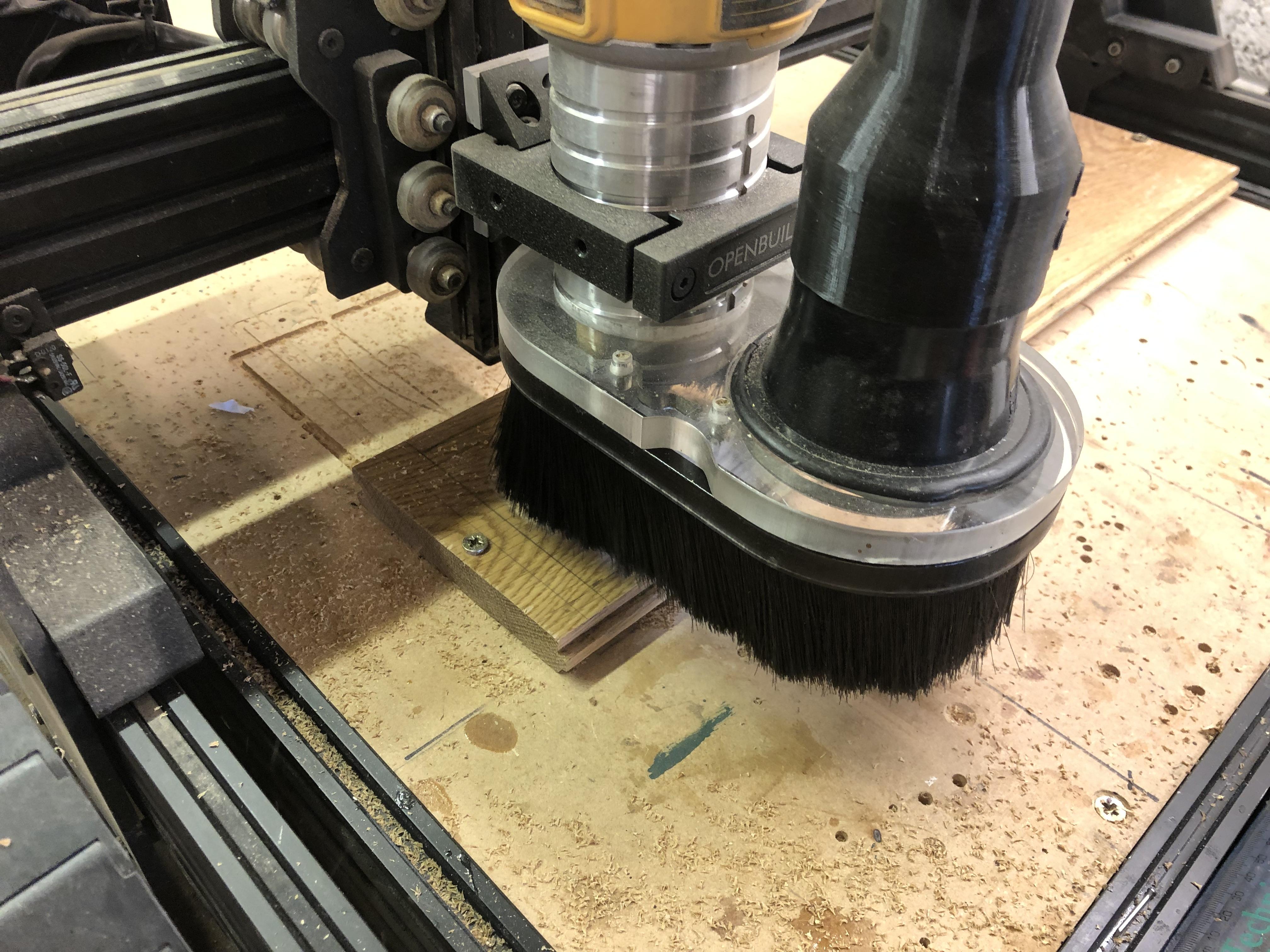
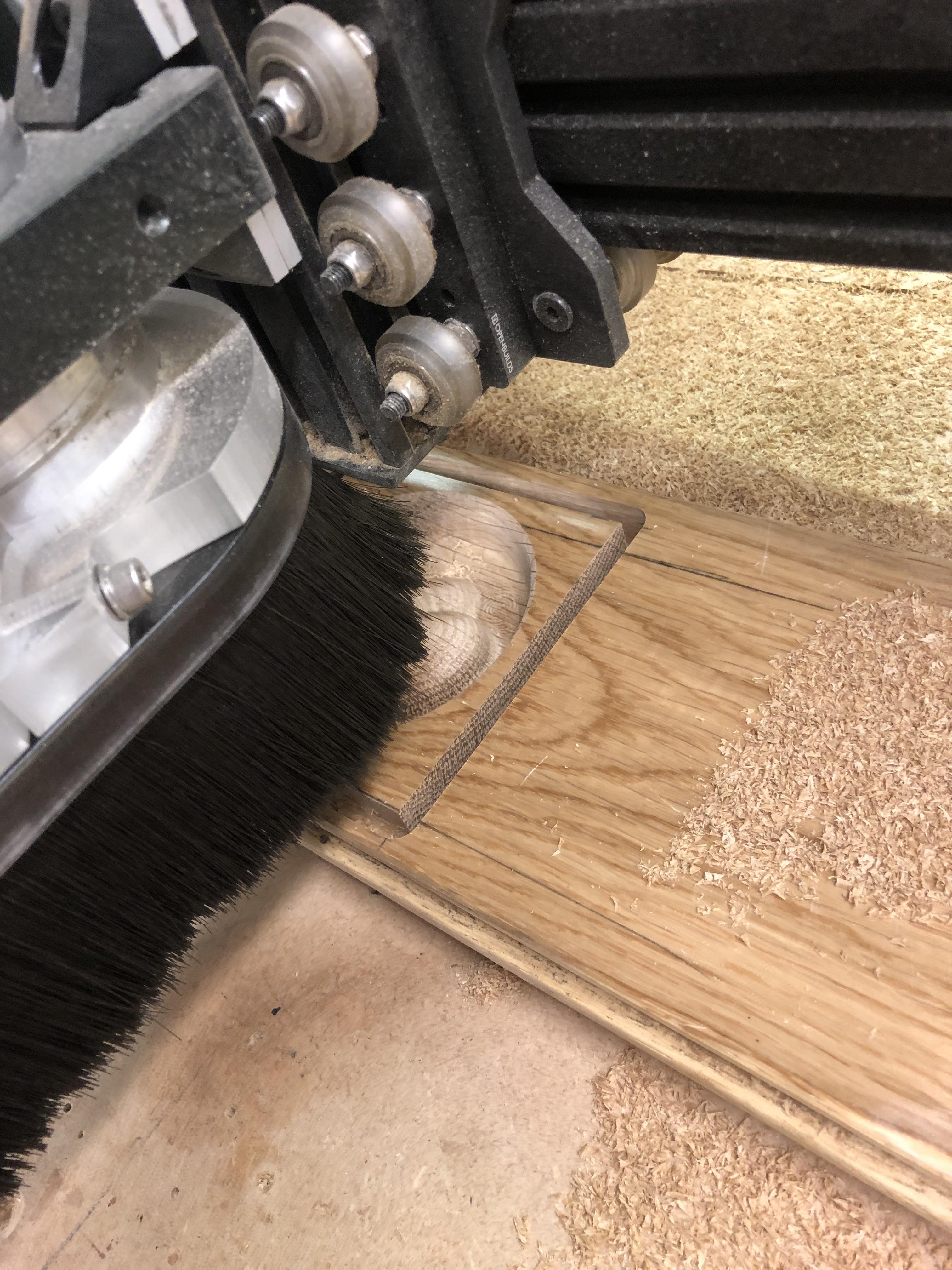
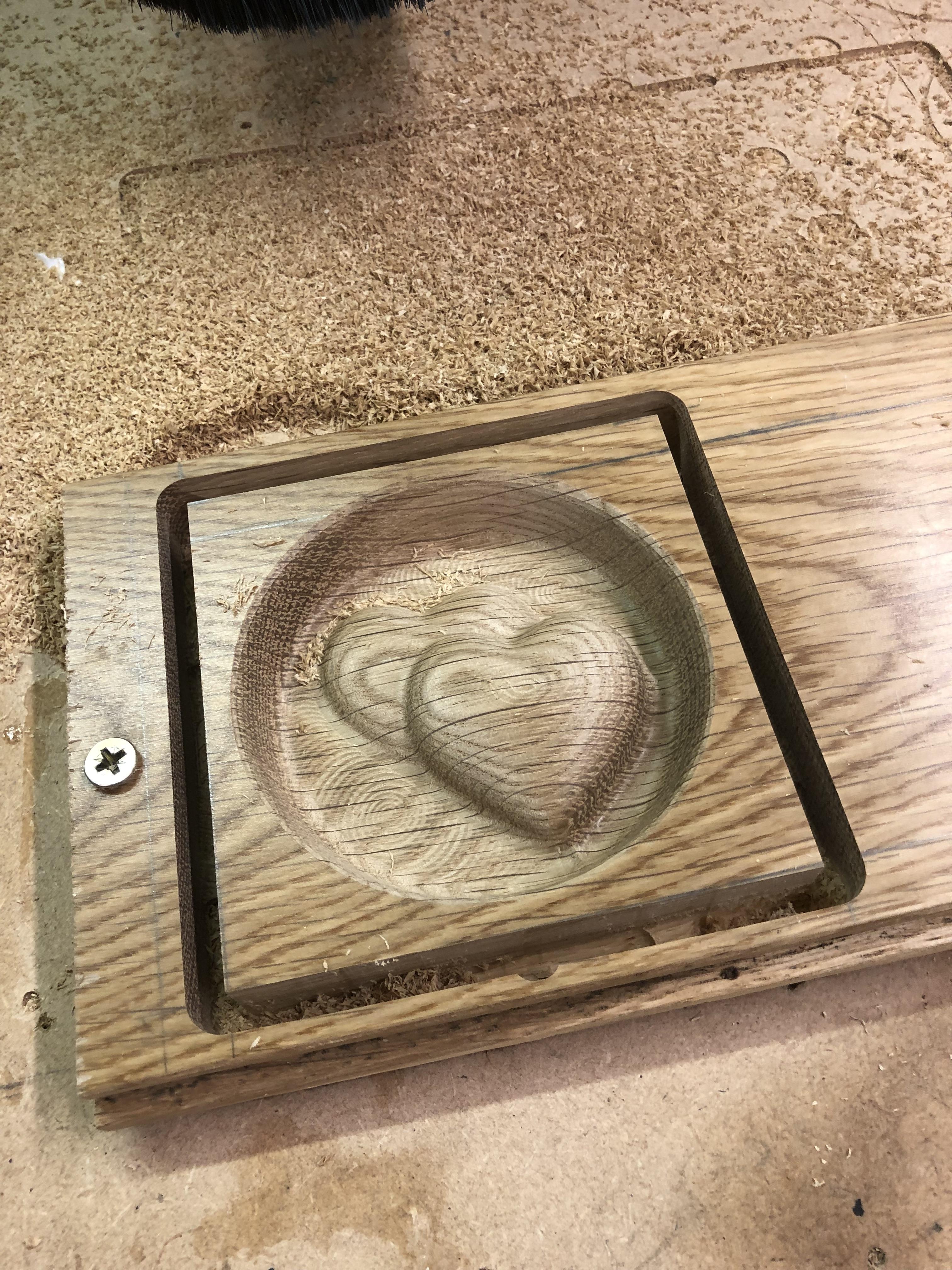
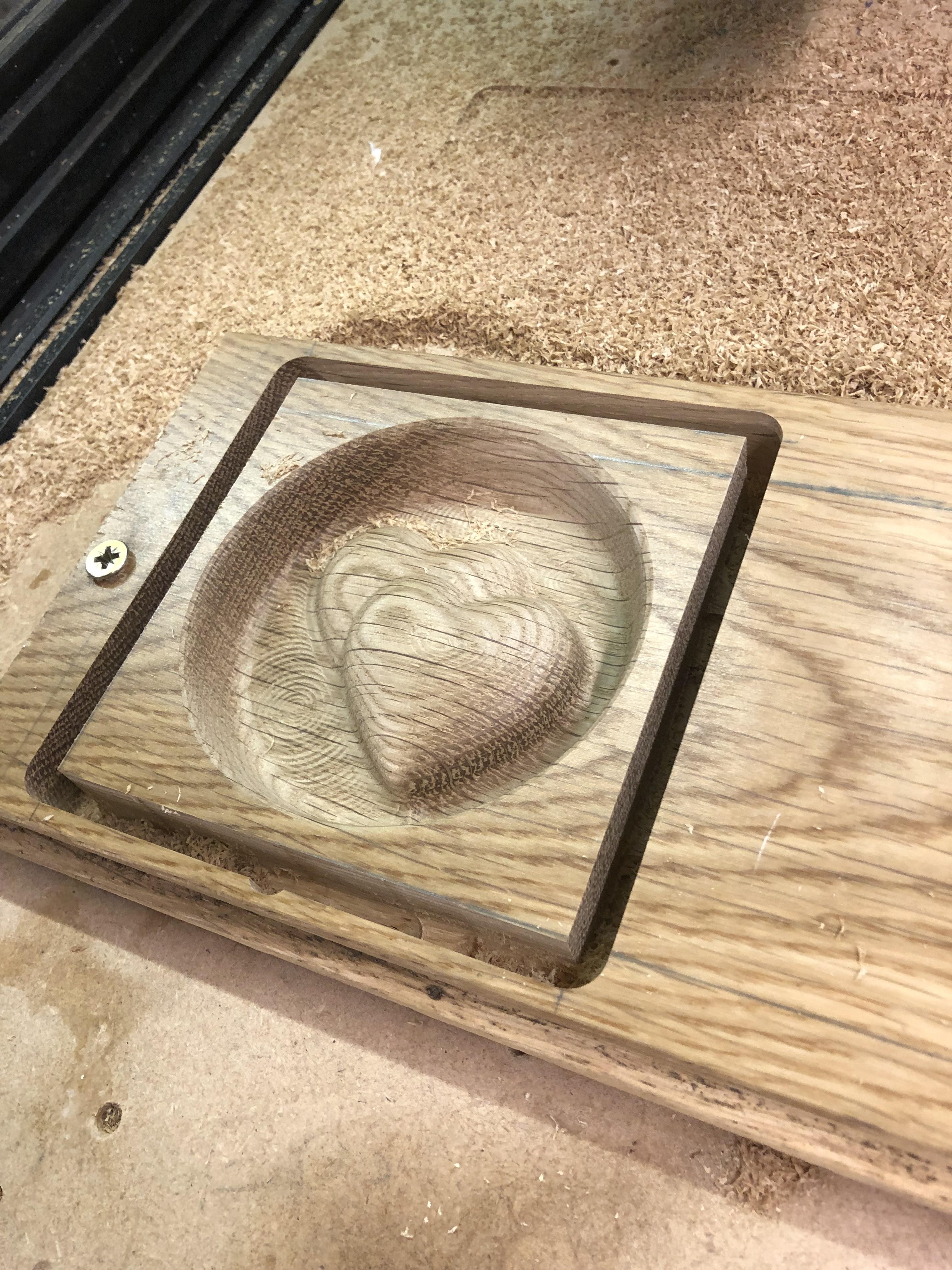
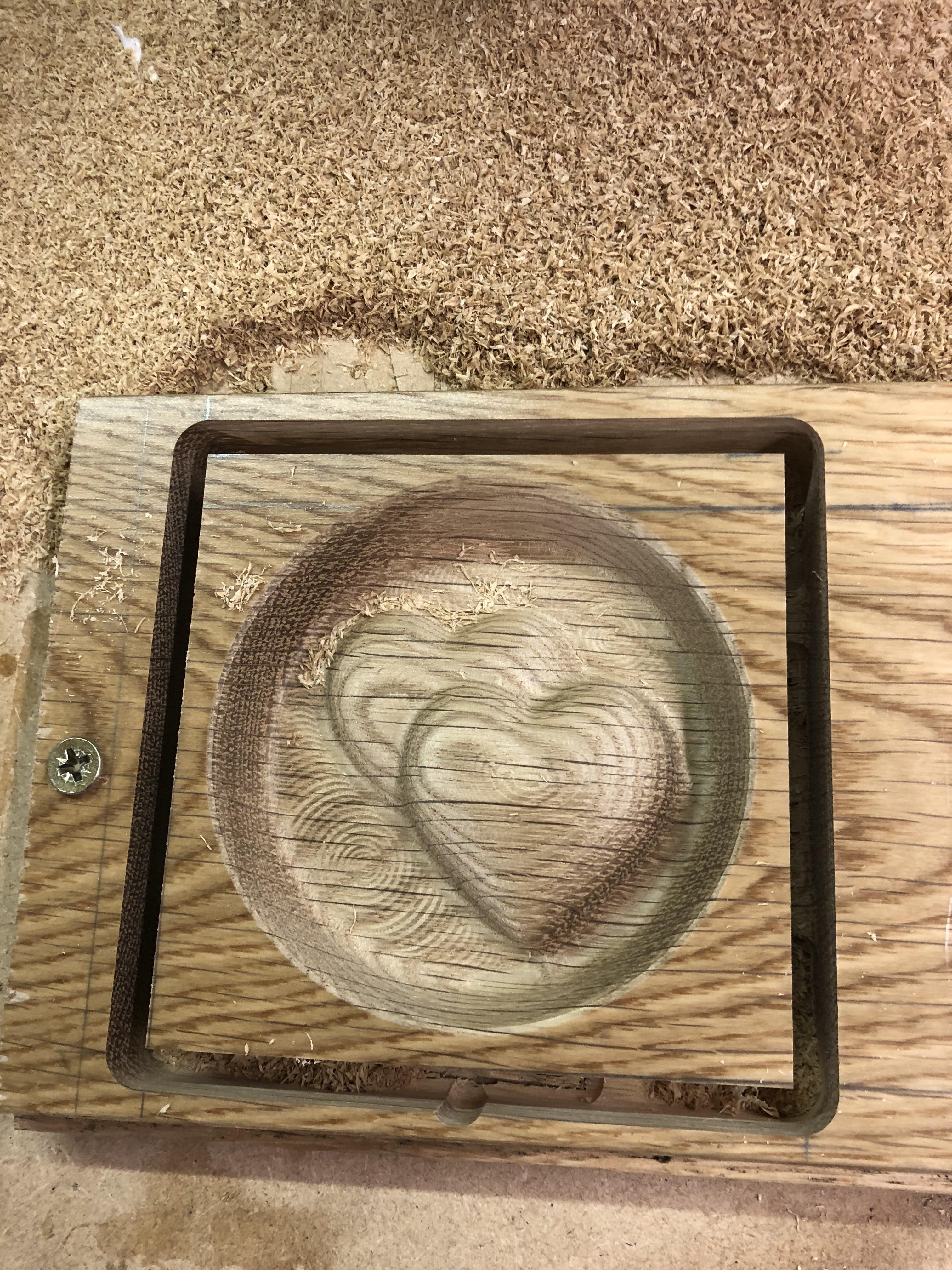
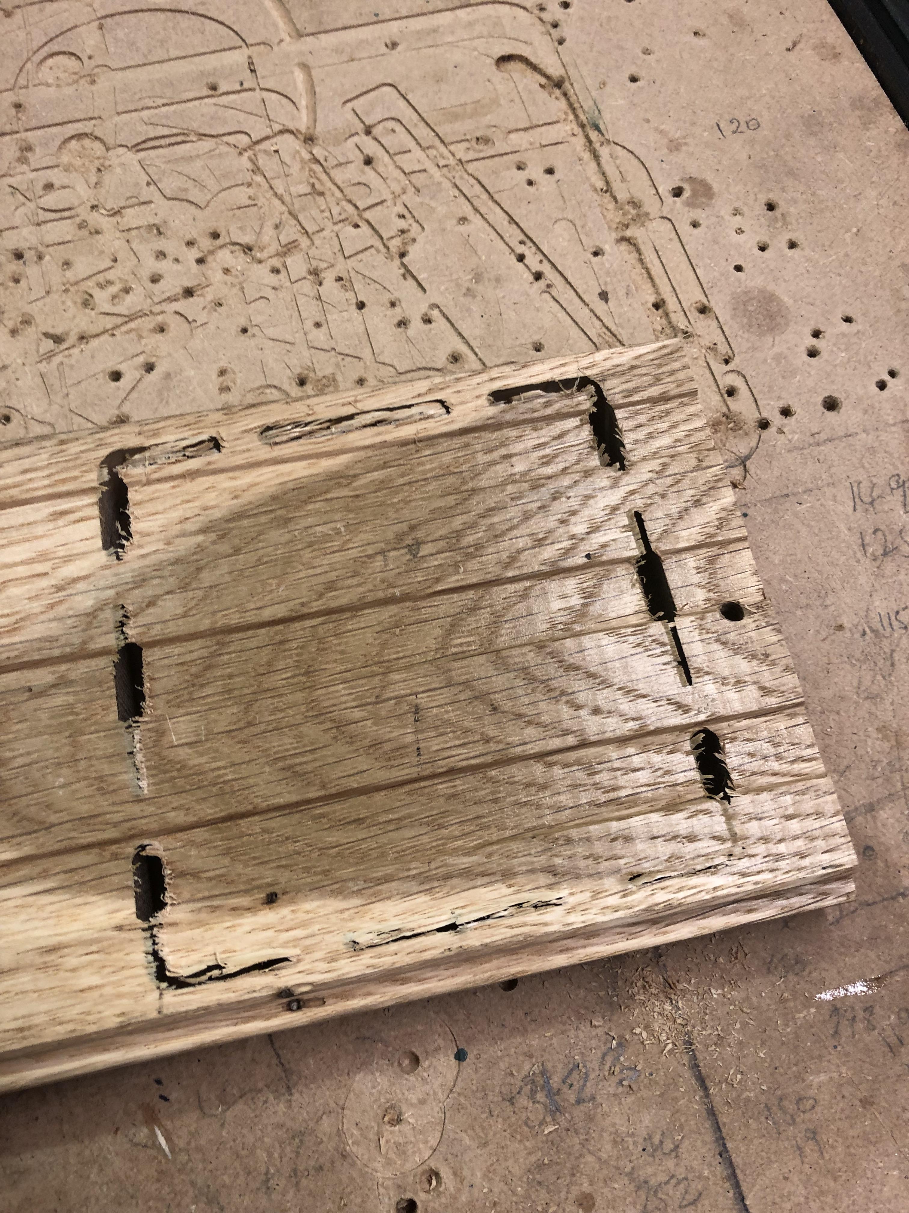
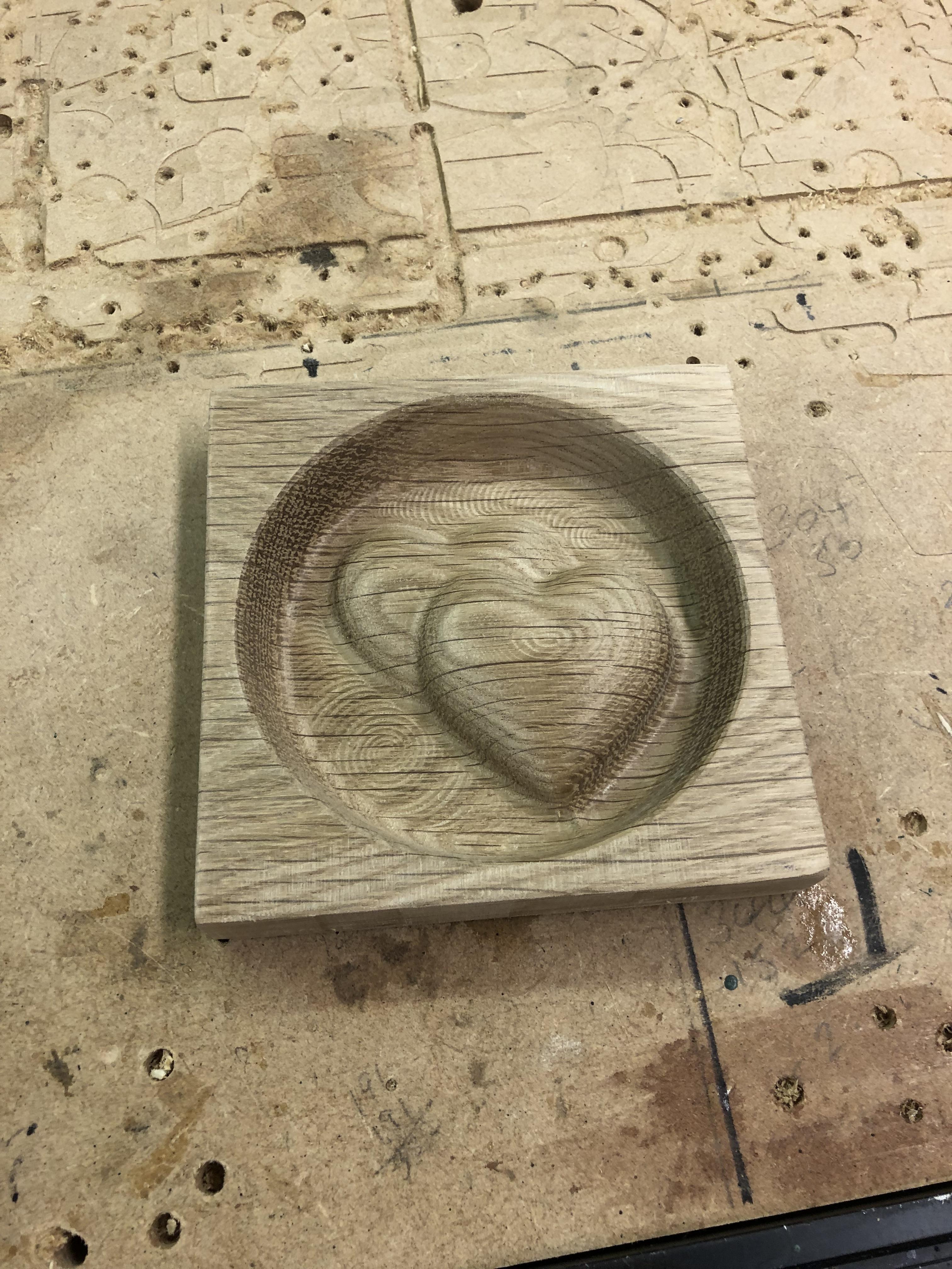
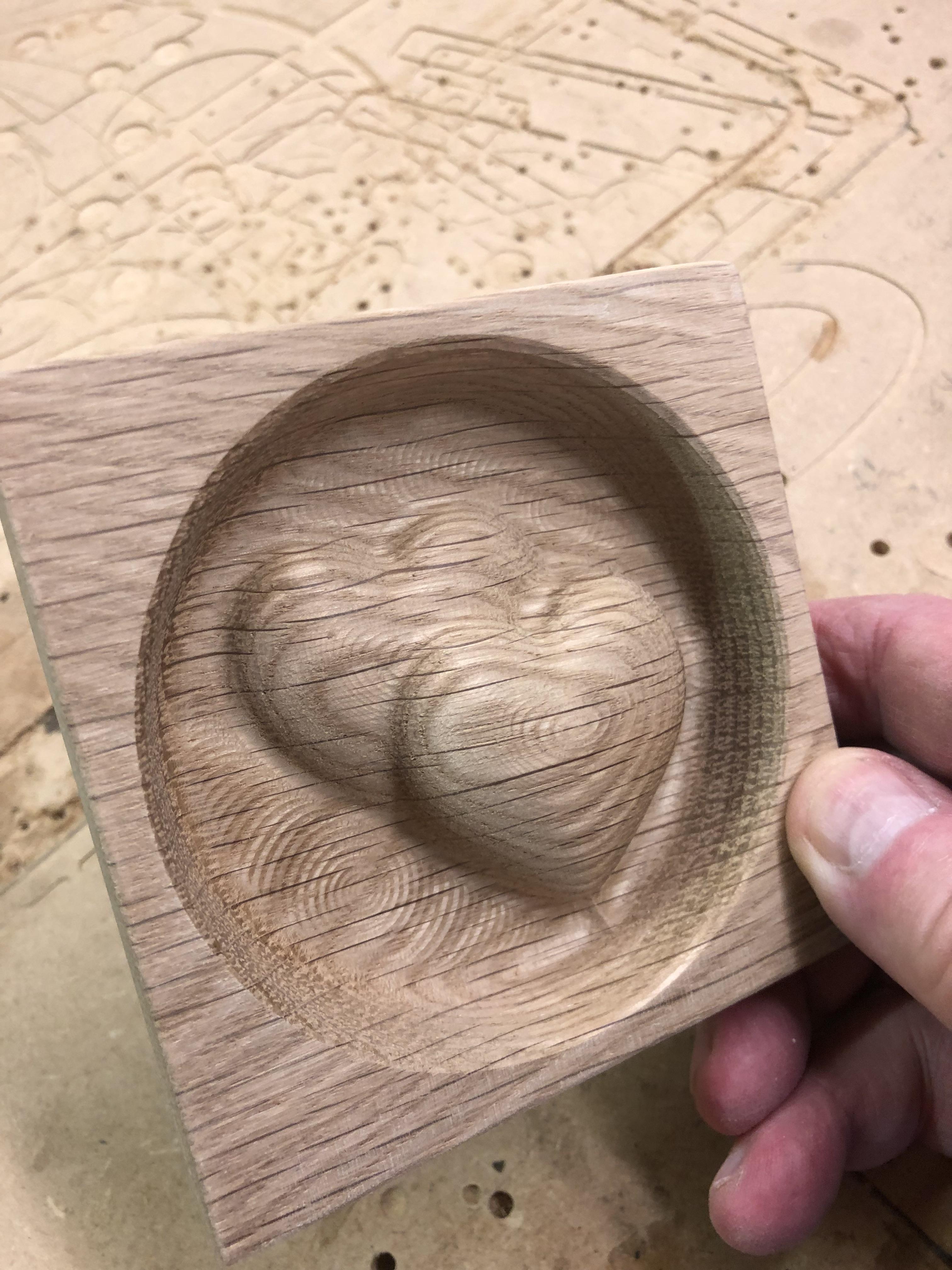
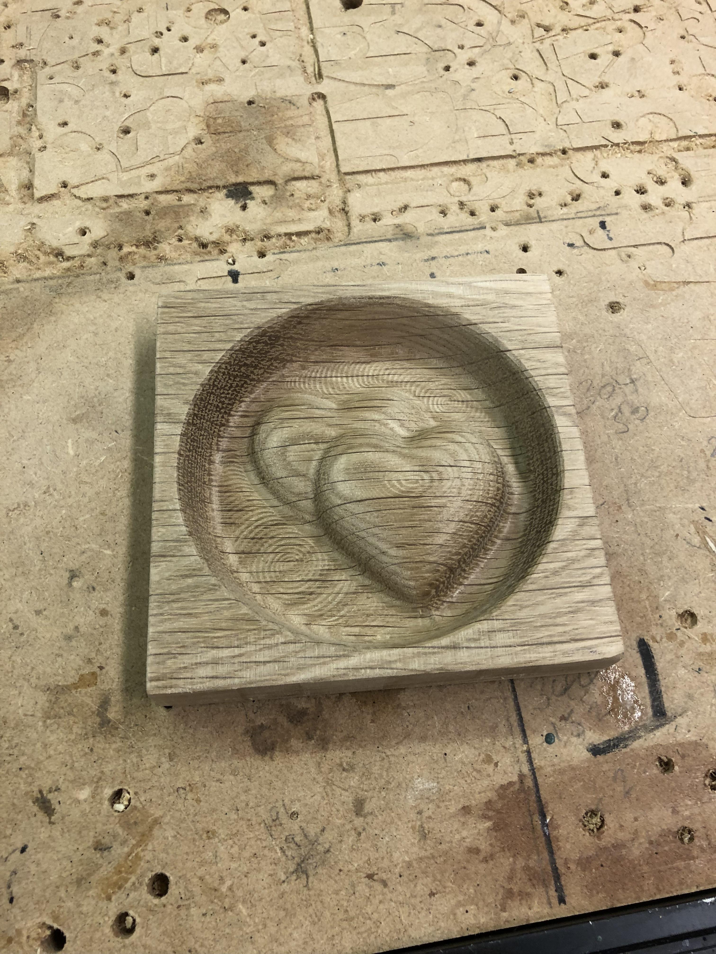
I drilled the floorboard in 2 positions, placed on the waste board then screwed it down, then marked out a 100mm square within the tongue and groove of the floorboard, using a ruler across the diagonals, I marked the centre position for the start of the cutting operation, the Zero, this was input into Universal G code Sender, I then raised the Z to fit the Dust Shoe, and returned to zero.
The file can now be input into UGS and clicking on start sets it off, Its a 90 minute cut, I could shorten this time by quite a bit but its an awkward piece to sand so selecting smoothing in the passes tab works for me on this occasion.
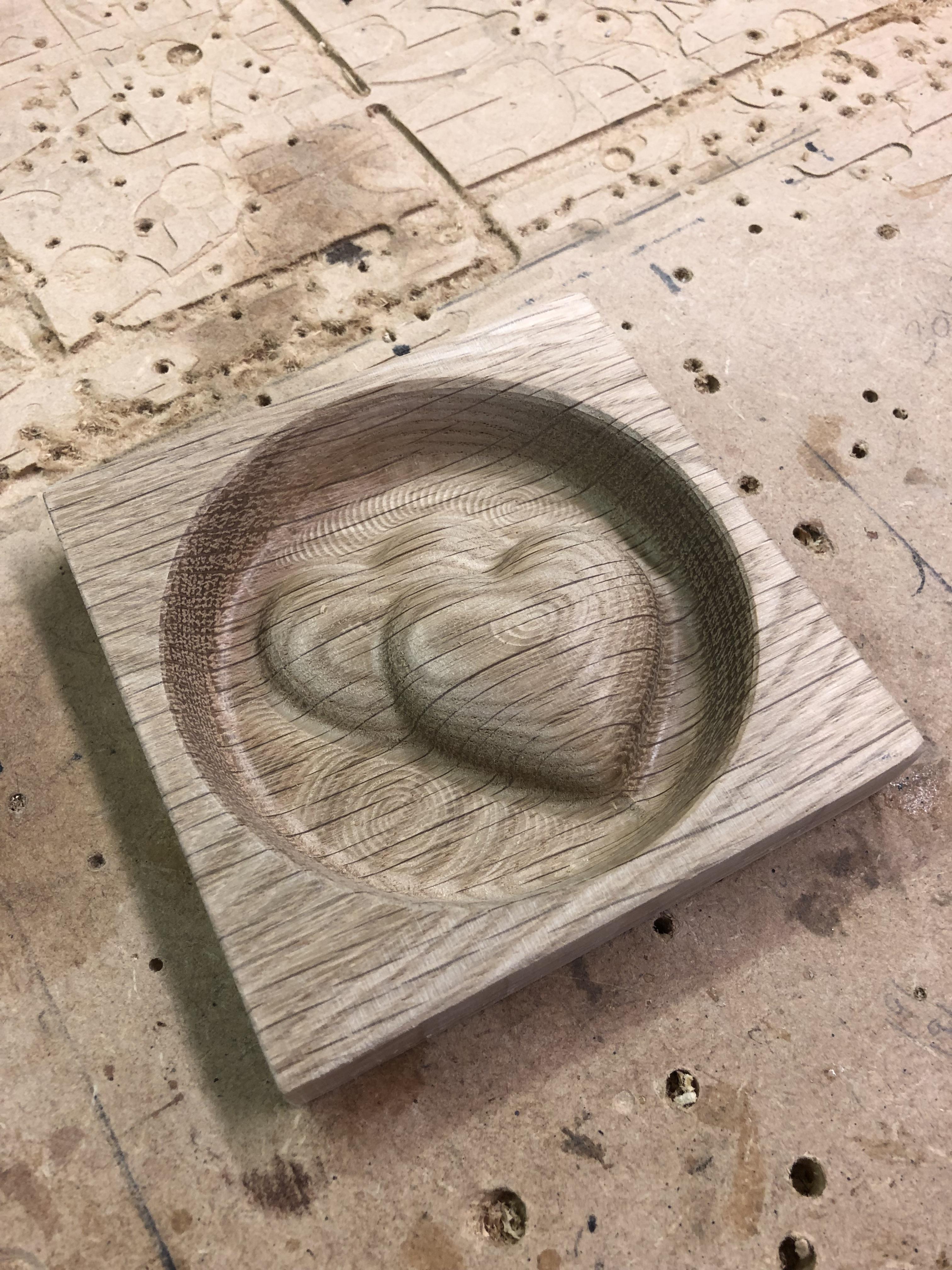
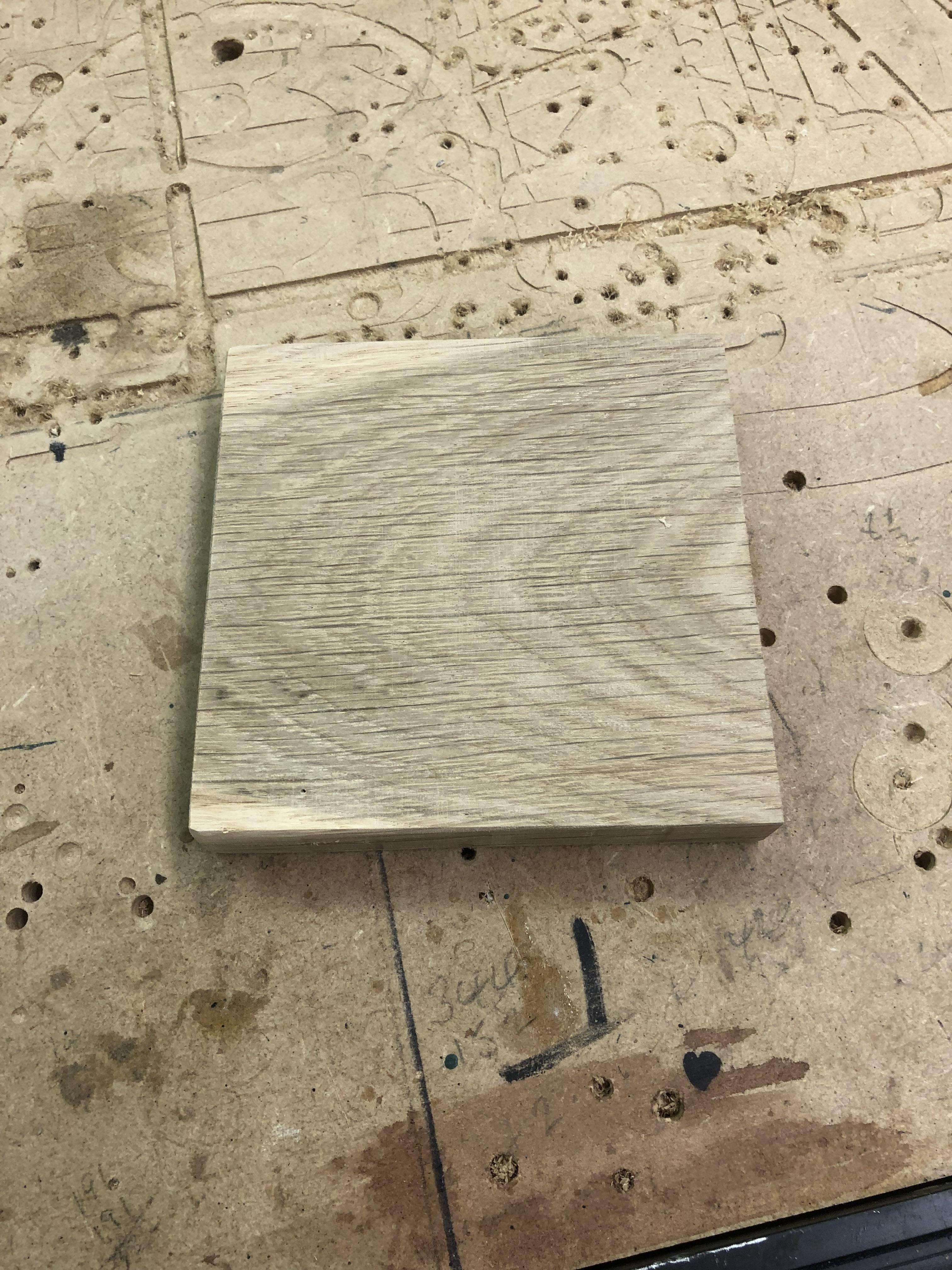
With the cut complete I release from the bed, and take it to the bandsaw and trim the tabs down etc, then sand the face, the back and edges and that's about it, all there is left to do is Laser the couples names on each one and a splash of boiled Linseed oil, Job done.
The summary:
Final Finish and Assumptions
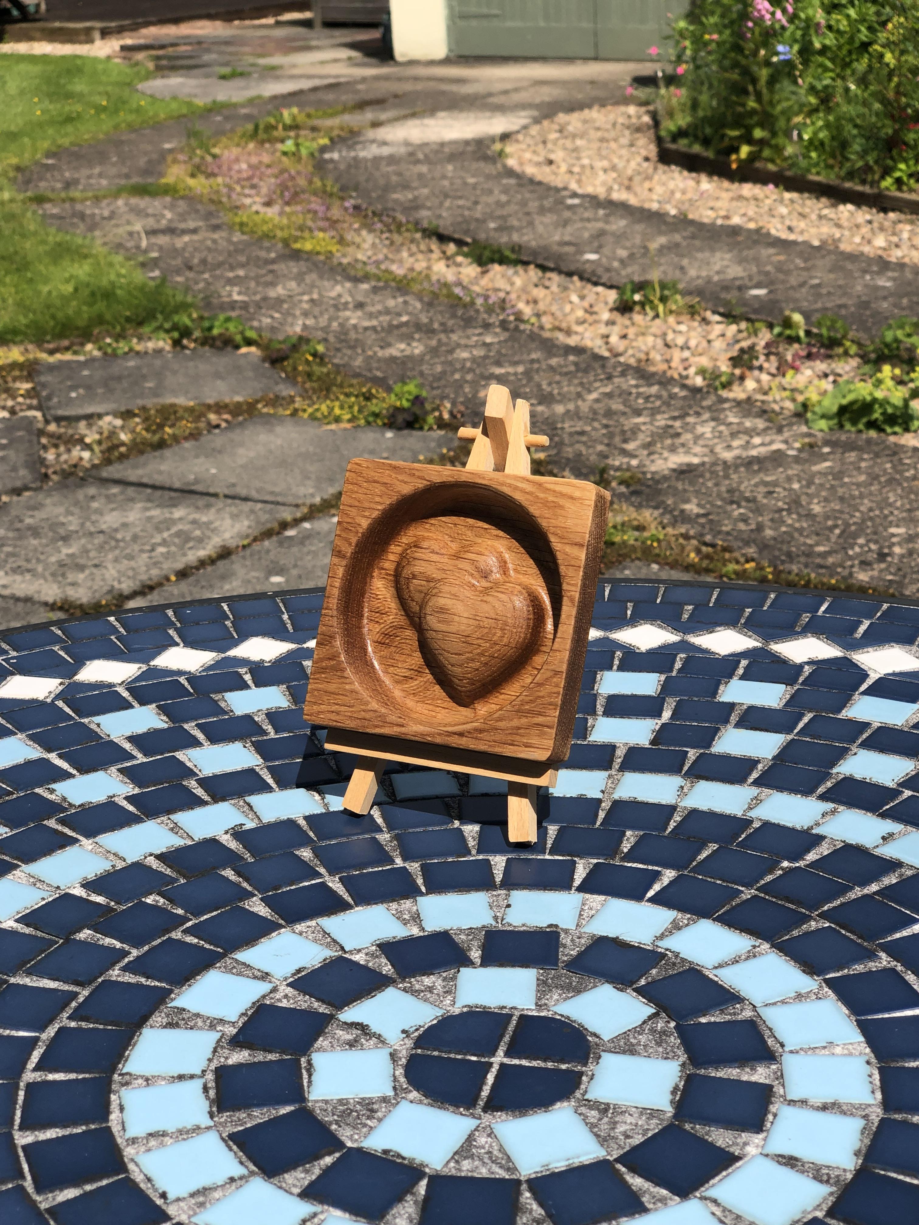
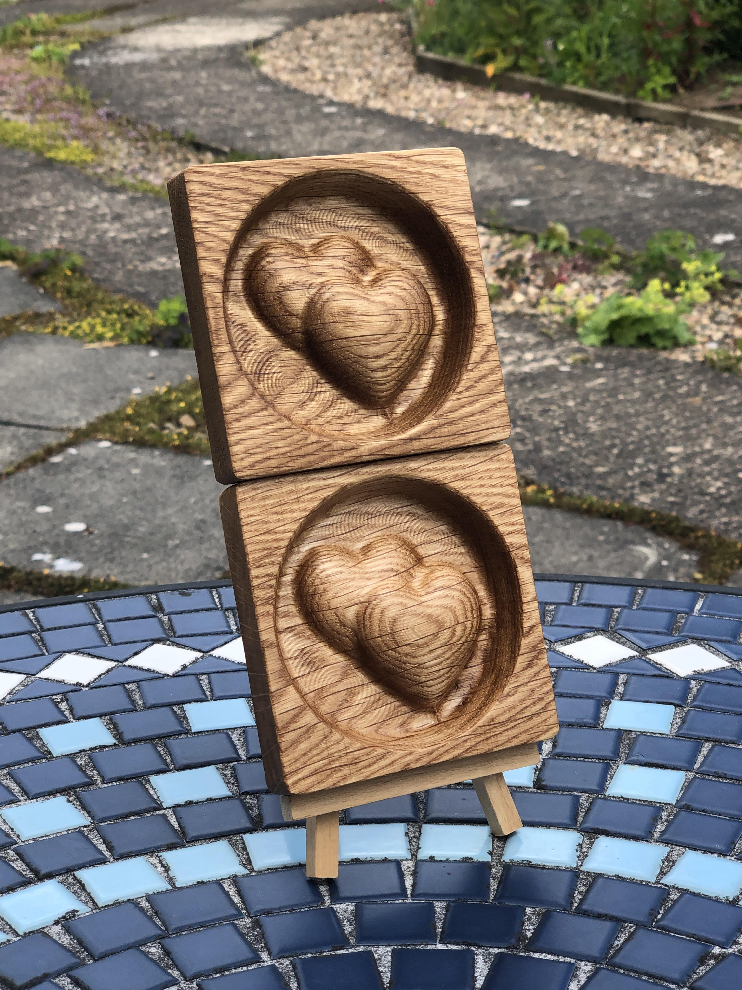
So if everything has gone to plan we will have a carved piece of wood with 2 Hearts, Using the 3D Adaptive clearing and smoothing there is very little sanding to do afterwards and for me I just use boiled linseed oil to finish, or it could be Danish Oil or even Wax.
You may have noticed that the Simulation in Fusion 360 is pretty much Identical to how the finished piece looks which is Incredible and never ceases to amaze me.
I think for someone who has been there and done it I can safely say that Initially using Fusion 360 and the Vetric software is very daunting, and watching some of the Tutorials out there make it even more confusing, don't get me wrong I take my hat off to anyone who has spent time putting a tutorial together out there but we are all different, I personally don't pick things up too easily at first, but once time is spent using the programs and trying things out on pieces scrap wood for yourself first then the results will start to come and it really can be very rewarding, be prepared for the failures, be prepared to turn the machine off rapidly, been there and done that too, and at times my Machine will just stop mid cutting which is annoying, it was limit switches at first causing this, so I removed them, but it still stops sometimes for no apparent reason, very rarely now, what I am using CNC wise is for the Hobbyist it happens, but overall its a great set up and I've done all sorts with it over the years, you get what you pay for in this game.
Anyway I hope with this Instructable and all the screenshots etc showing the whole process from design to Manufacturing that it can help people who were maybe like me when I first set off on the CNC Diy journey, it is daunting at first, but like anything else, it becomes easier with time, there are fundamental processes you have to go through before pressing the start button, with these boxes ticked all should be ok.
And this train of thought just doesn't apply to CNC, could be Electronics, Arduino, anything Diy, you name it.
I hope you enjoyed the Instructable and thanks for looking.