2 Bit Adder Binary and Decimal Calculator
by sonyasingh in Circuits > Arduino
5747 Views, 3 Favorites, 0 Comments
2 Bit Adder Binary and Decimal Calculator
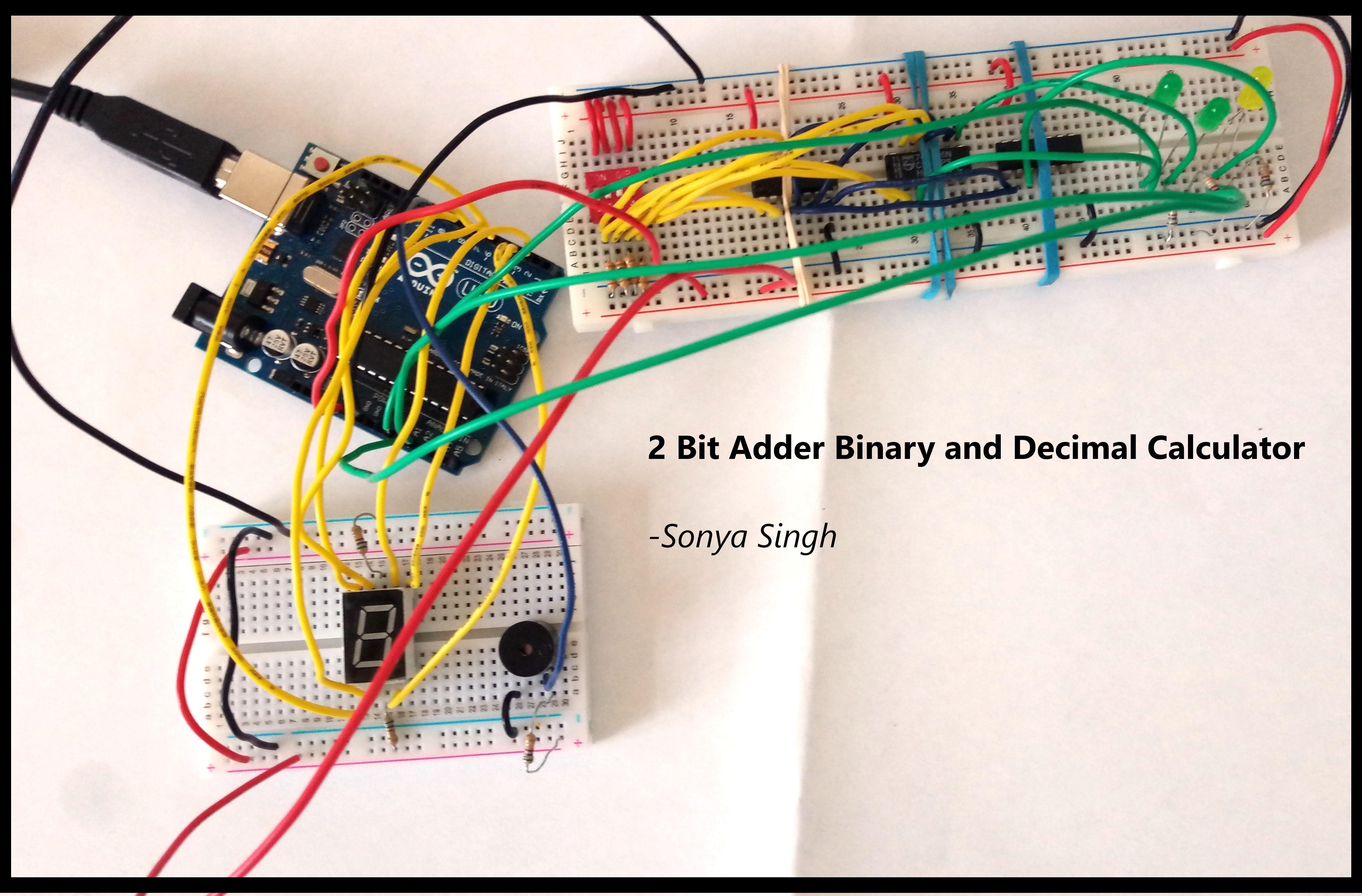
By: Sonya Singh
Computer Engineering
Project Overview
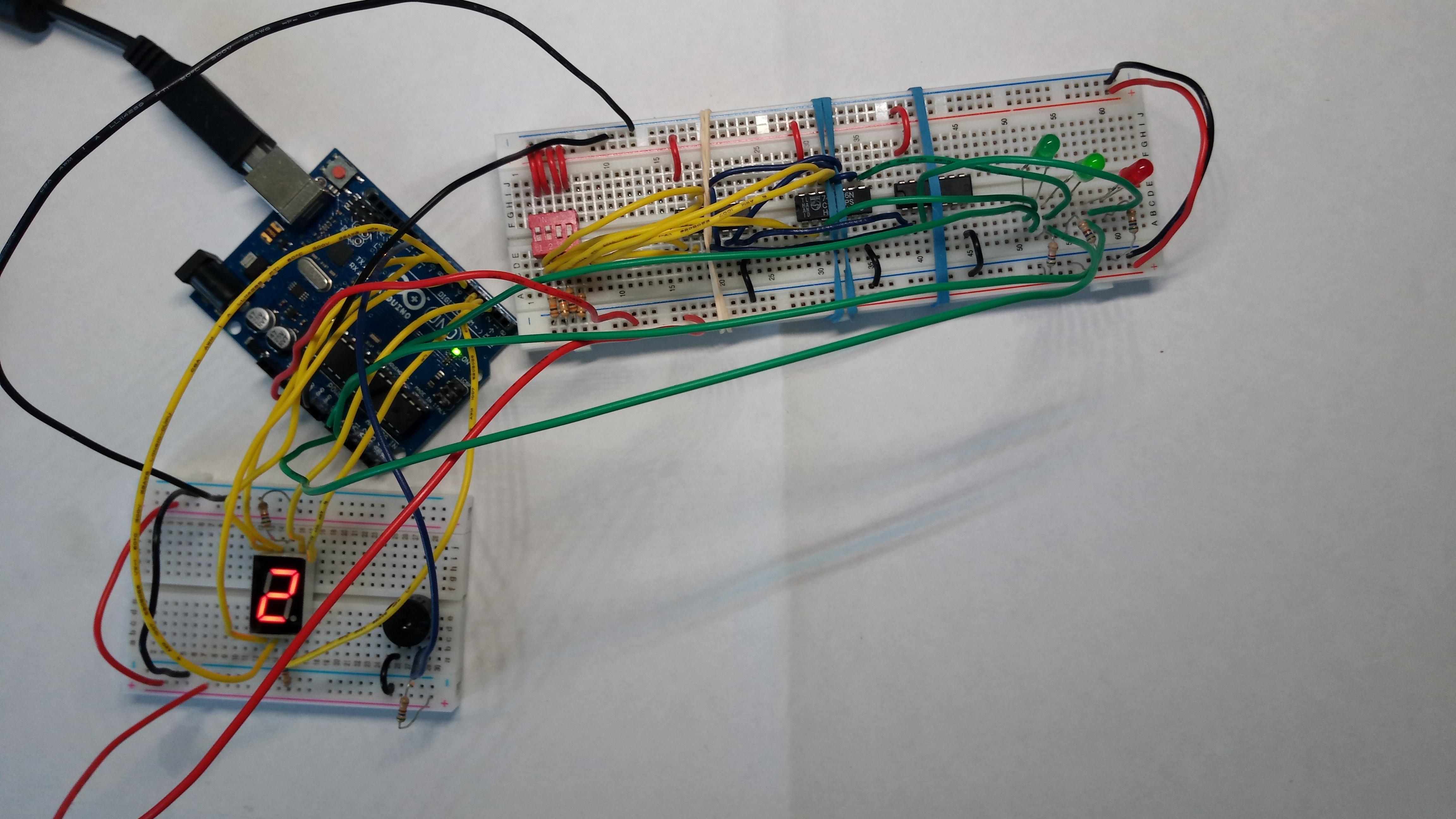
Have you ever dreamed of building a 2-bit adder calculator, which can display the results in both binary and decimal?
Well, look no further - Through this guide, your dreams have finally come true! Not only will you learn to build the adder, but you'll also have fun doing so.
Contents
1. Project overview
2. Revisiting the fundamentals
a. Binary Logic 101
b. Adder 101
3. Let’s build the hardware
a. Required Components
b. Assemble the 2-bit Adder- Understanding
c. Assemble the 2-bit Adder- Starting the Build
d. Test the Circuit
e. Output Devices - 7 Segment Display & Buzzer
4. Let’s write the software
a. About the code
b. Arduino Code
5. Let’s see it in action
a. Final Testing
b. Video
Project Overview
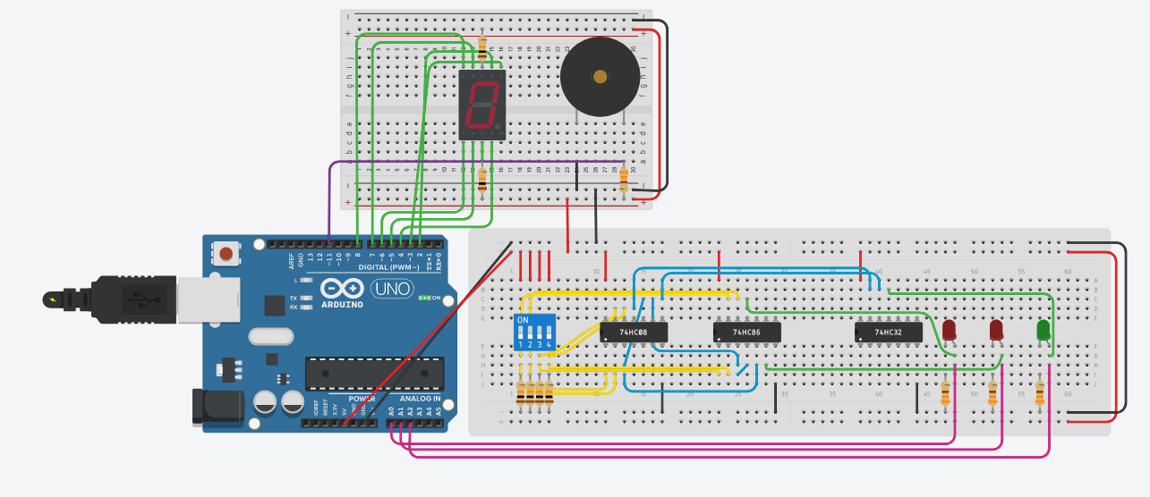
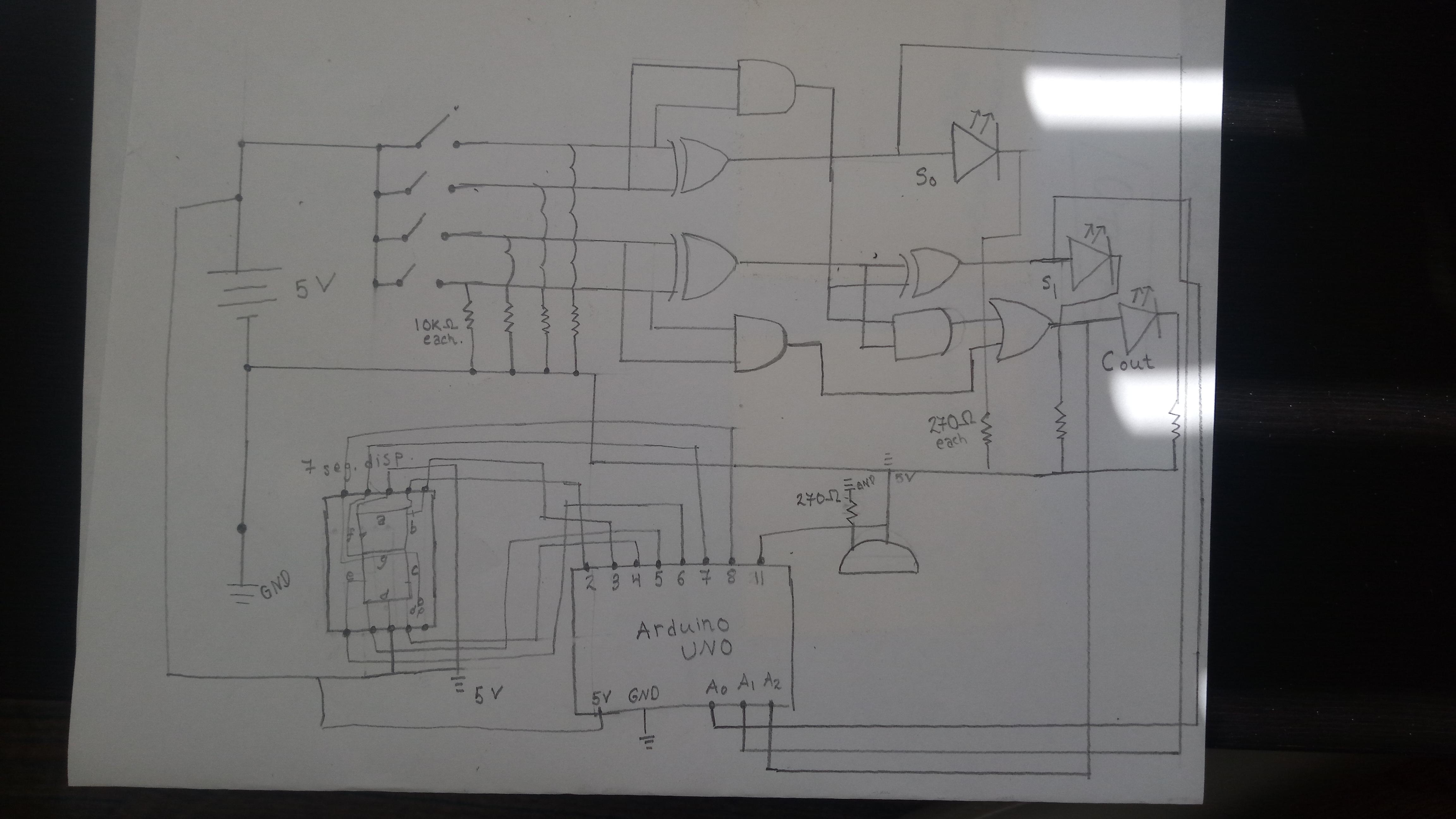
This circuit serves as a calculator and the converter of binary and decimal values between 0 to 6.
The 2-bit adder outputs to LEDs, which indicate the binary number, and a 7 segment display, which shows the same number in decimal form.
This project is useful for those who are delving into binary logic.
This project is completely customizable! The number of bits in the adder can be adjusted, along with the number of LEDs and 7 segment displays being used.
As you will see in my procedure, I have added an additional component to my project, just for fun!
Revisiting the Fundamentals: Binary Logic 101
The Binary Number system is most commonly used in Computers. Everything stored on a computer exists as a series of bits (Binary Digits).
Fun fact: 1 megabyte contains over 8 billion bits.
In Binary language, there are only two number values, 0 and 1- Which makes it the lowest base number system. Computers process a series of 0s and 1s to perform certain operations and receive/retain data.
So how can only 1s and 0s be used to make various numerical values?
Each digit's position has a corresponding decimal value. These increase by powers of 2. The left-most digit is considered the most significant bit, and the rightmost is considered the least significant bit.
Let's try converting!
Binary to Decimal
Label each of the bits in terms of their powers of two. From the right, write the values of 1,2,4,8…depending on how many bits there are in the number. Add the placeholders up for any digit that is a 1.
EXAMPLE Convert 100101₂ to Decimal
Most Significant Bit → 1 0 0 1 0 1 ← Least Significant Bit
2⁵ 2⁴ 2³ 2² 2¹ 2⁰ ← Use the powers of 2 as placeholders
32 16 8 4 2 1 ← Write in decimal Form
Now add: 32+4+1 = 37
37₁₀
Decimal to binary
*Thanks Ms.Edwards for this!!!
EXAMPLE Converting 238710 to BINARY
STEP 1: Write out the place holders
65536 32788 16384 8192 4096 2048 1024 512 256 128 64 32 16 8 4 2 1
STEP 2: Find the closest but not bigger number, in this case 2048 subtract it from the beginning number and write a 1 underneath the place holder, repeat this until you get to 0
2387 – 2048 = 339 put 1 in the 2048 column
339 – 256 = 83 put 1 in the 256 column
83 – 64 = 19 put 1 in the 64 column
19 – 16 = 3 put 1 in the 16 column
3 – 2 = 1 put 1 in the 2 column
1 – 1 = 0 put 1 in the 1 column
65536 32788 16384 8192 4096 2048 1024 512 256 128 64 32 16 8 4 2 1
1 1 1 1 1 1
STEP 3: FILL in every other place with zeroes.
65536 32788 16384 8192 4096 2048 1024 512 256 128 64 32 16 8 4 2 1
0 0 0 0 0 1 0 0 1 0 1 0 1 0 0 1 1 = 10010101001
Revisiting the Fundamentals: Adders 101
When Binary numbers need to be added together, all the possible combinations of additions are compiled into a truth table. When 1-bit values are being added together, the smallest truth table, with 4 combinations are formed.
An adder can add any number of inputs to produce an output.
The adder computes the inputs using logic gates.
Logic gates are the basic building block of digital systems and circuits, they contain binary inputs that produce binary outputs. The truth tables of the logic gates show all the possible combinations for the binary inputs and outputs.
Let's Build the Hardware: Required Components
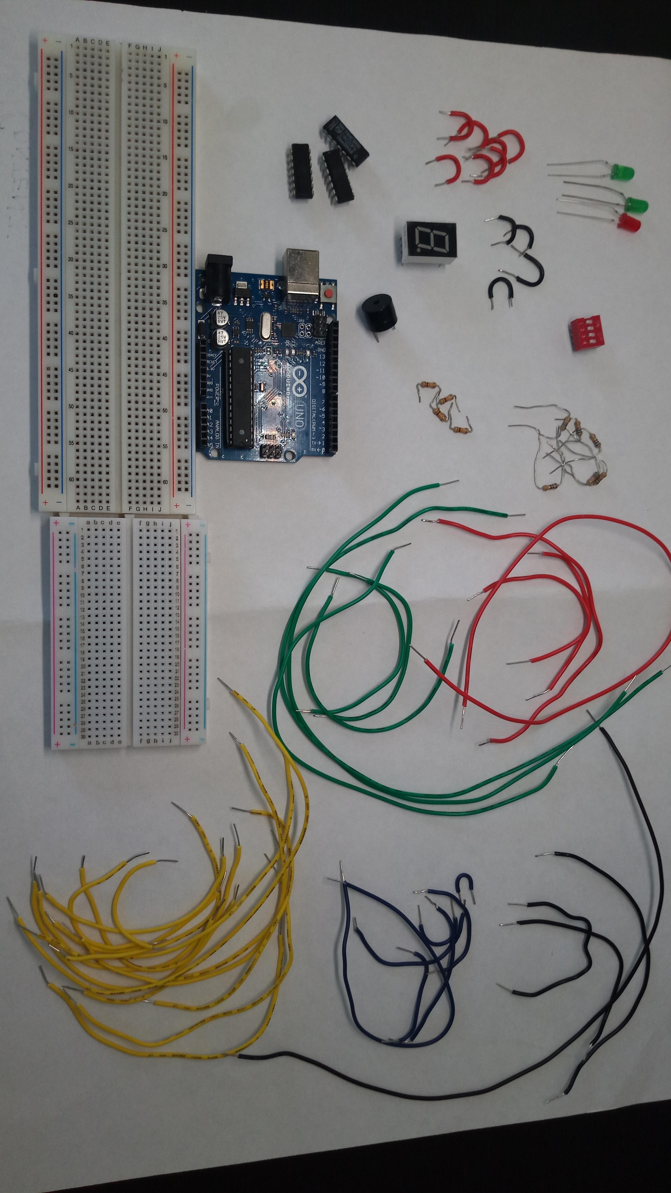
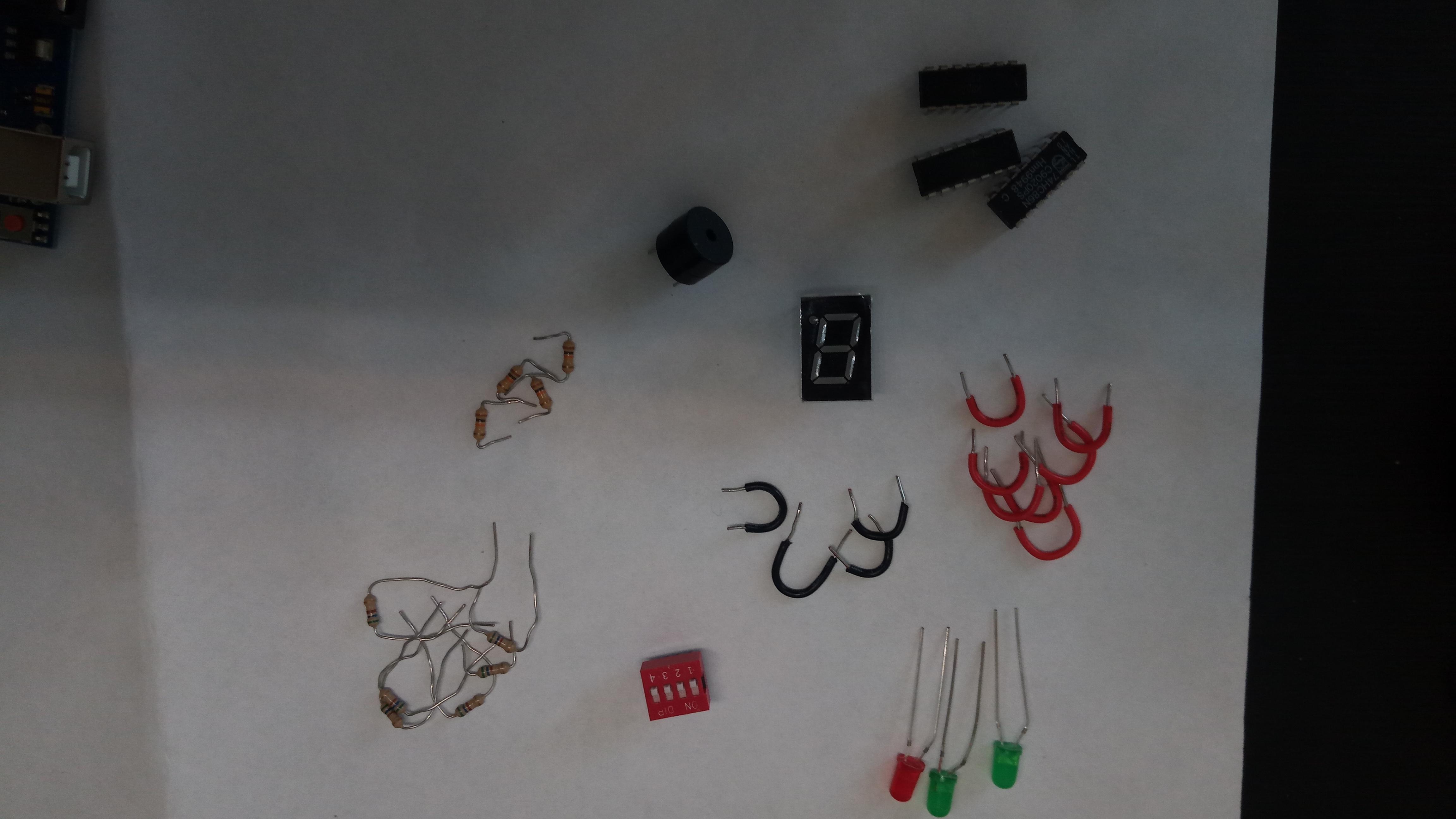
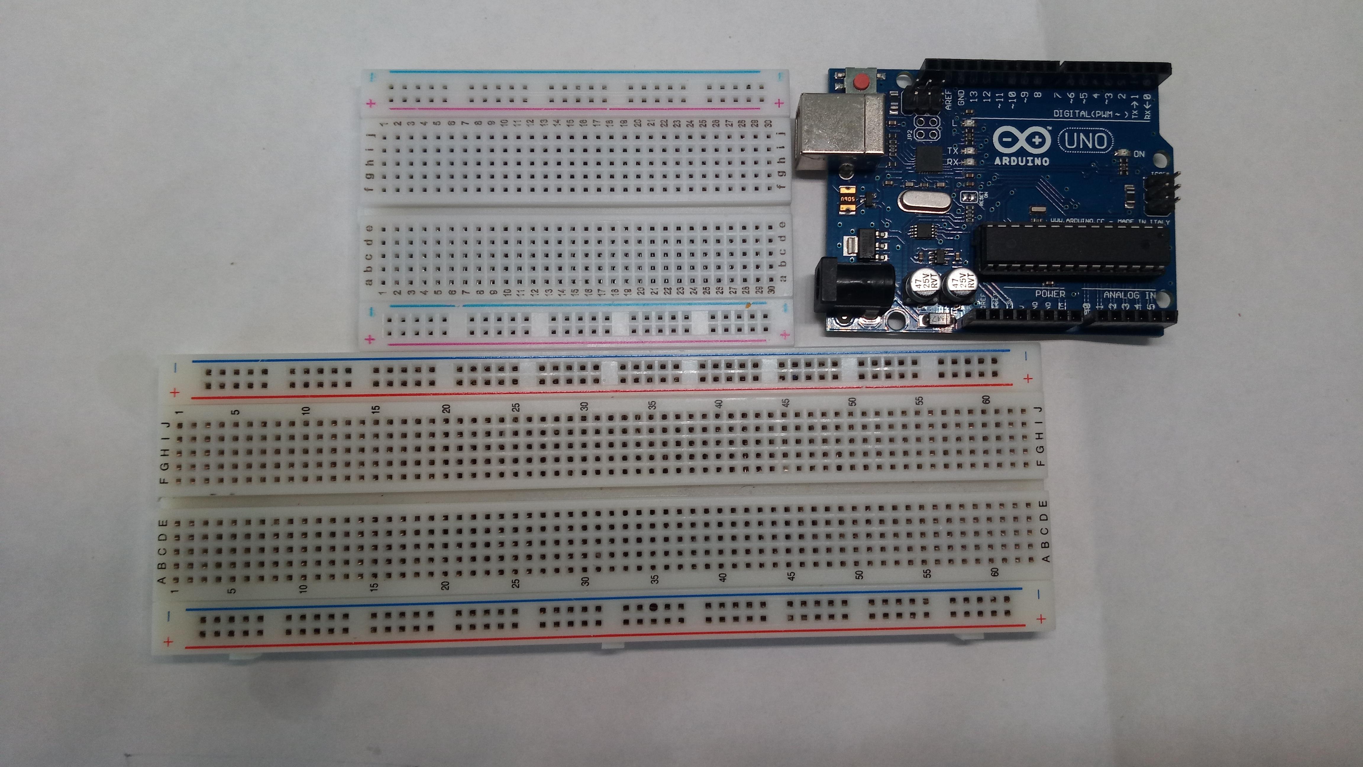

Gather all these components for the build.
You will need:
● 1 x Large Solderless Breadboard
● 1 x Small Solderless Breadboard (Optional, but highly recommended)
● 3 x Logic Chips
● 3 x LEDs
○ 2 Green LEDs (Sums)
○ 1 Red LED (CarryOut Value)
● 1 x Dipswitch (With 4 inputs)
Additional Items
● Lots of wire (Try to use at least 5 colours, to distinguish the various sectors of the circuit)
● Arduino IDE Software (You can download it for free on the Arduino Website)
● USB cable (for the arduino data and power)
● Rubber bands (optional)
Let’s Build the Hardware: Assemble the 2-bit Adder- Understanding
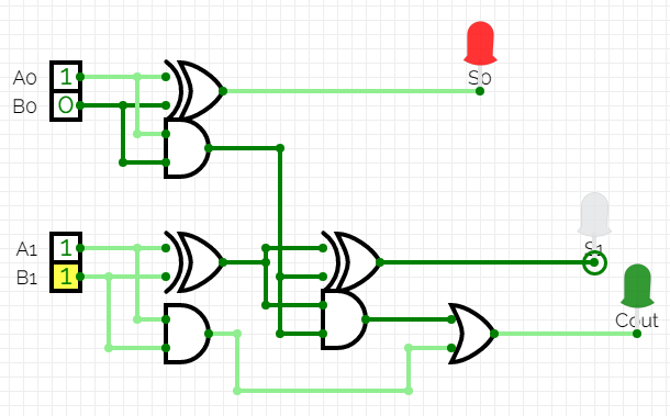

1. Let’s begin the build for the 2-bit adder. Follow the schematic to ensure the wires are going into the correct logic gates. (Recall, that each chip has 4 logic gates with 8 inputs and 4 outputs).
2. Play around with the schematic by creating it yourself to develop further understanding. You will observe how the inputs affect the binary output.
I have also attached an image of the wiring for the 2-bit Adder.
Let’s Build the Hardware: Assemble the 2-bit Adder- Starting the Build
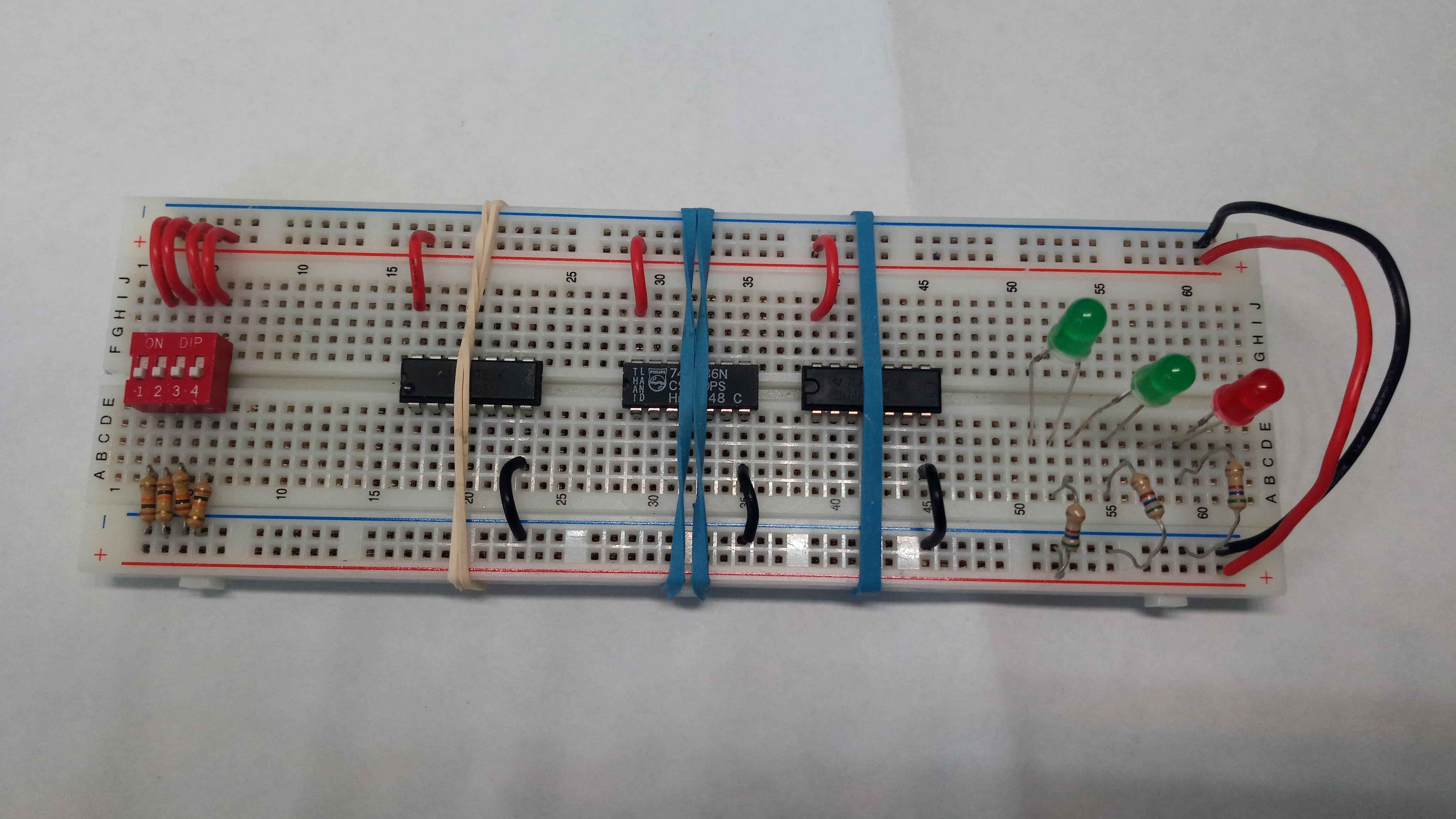
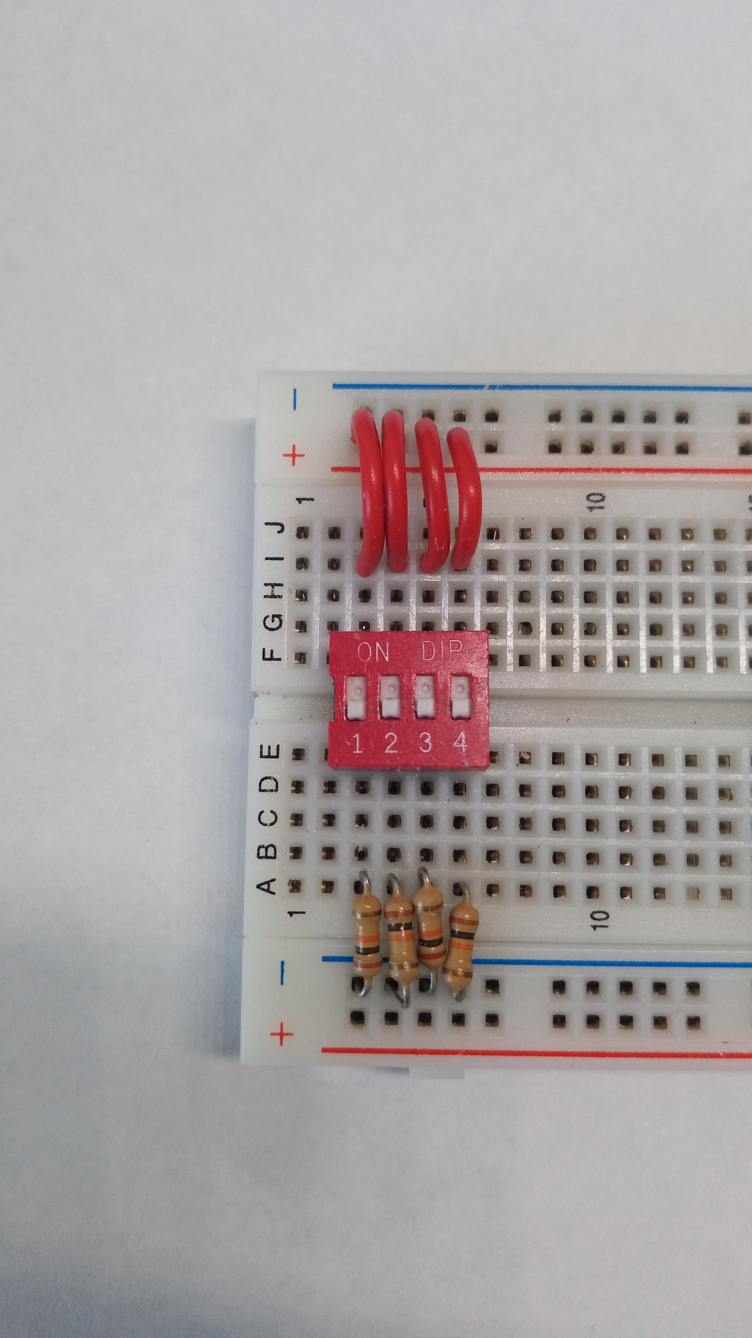
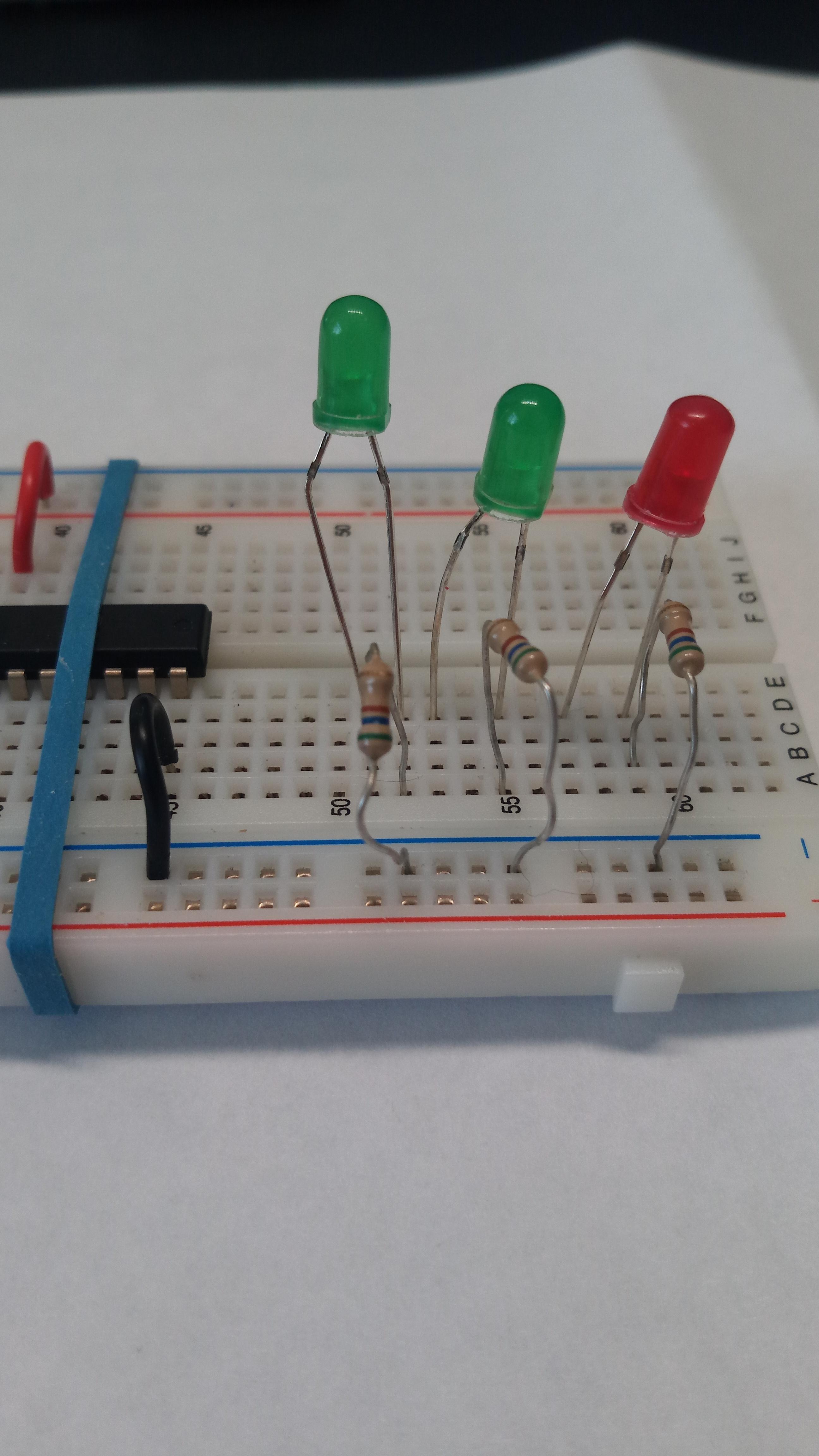
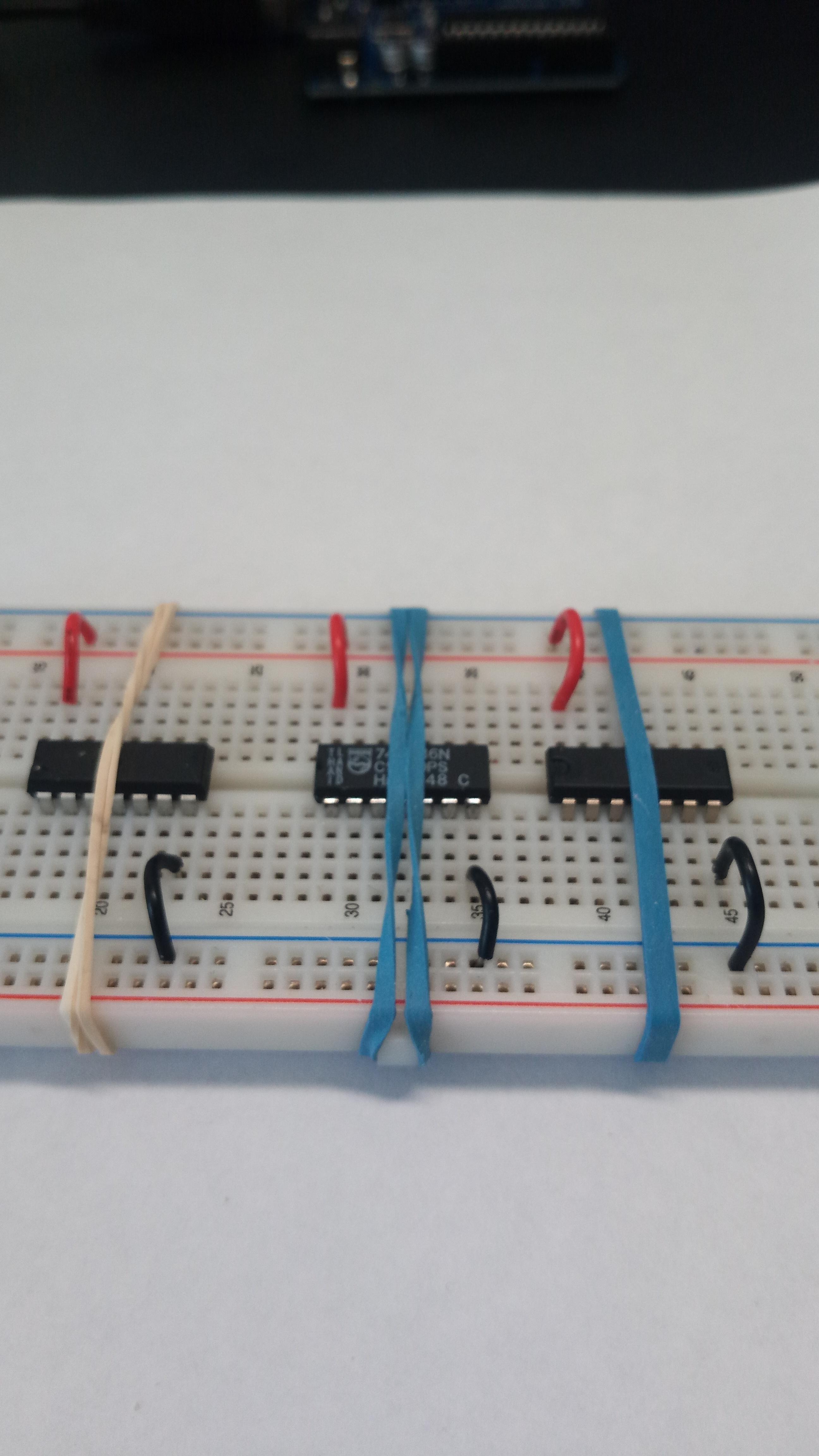
1. Place the dip switch near the left-most end of the breadboard. Connect the top pins to power, and the bottom pins to ground with each of the 10kΩ resistors.
The dipswitch inputs are as follows:
1 is A0 and 2 is B0 ←-- These are the least significant digits.
3 is A1 and 4 is B1 ←-- These are the most significant digits.
When the digits are added, they produce a binary value of up to three digits. (The maximum number, in this case, is 6.)
1<----Carry
11<---A1 and A0
+11<--- B1 and B0
101 = 6
2. I would suggest placing the XOR chip closest to the dip switch, followed by the AND chip, and finally the OR chip. Connect the top left pin of the chip to power and the bottom-right pin to ground.
3. Add the three LEDs to the right end of the Breadboard. Connect the cathode to the ground. The anode will receive power from the outputs of the logic gates.
4. Order the LEDs from Least significant to most significant. The Sums and Carryout should be two different colours. Connect each of the anode legs of the LEDs to the Analog inputs of A0, A1 and A2 on the Arduino UNO.
Let’s Build the Hardware: Complete and Test the Adder Circuit
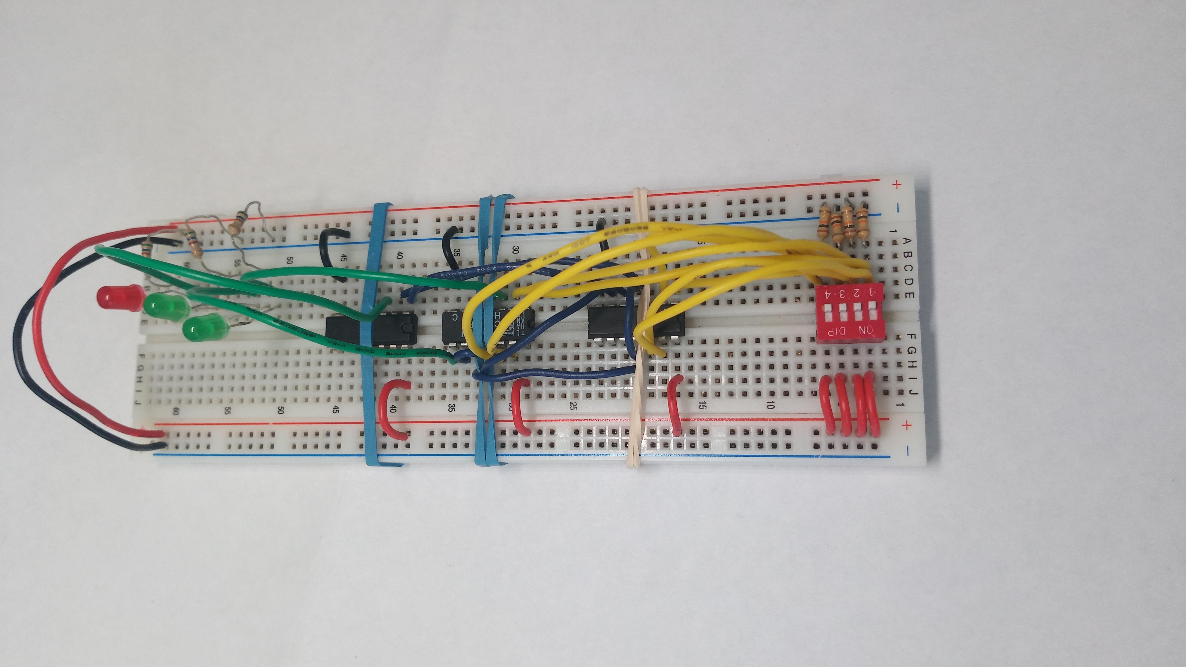
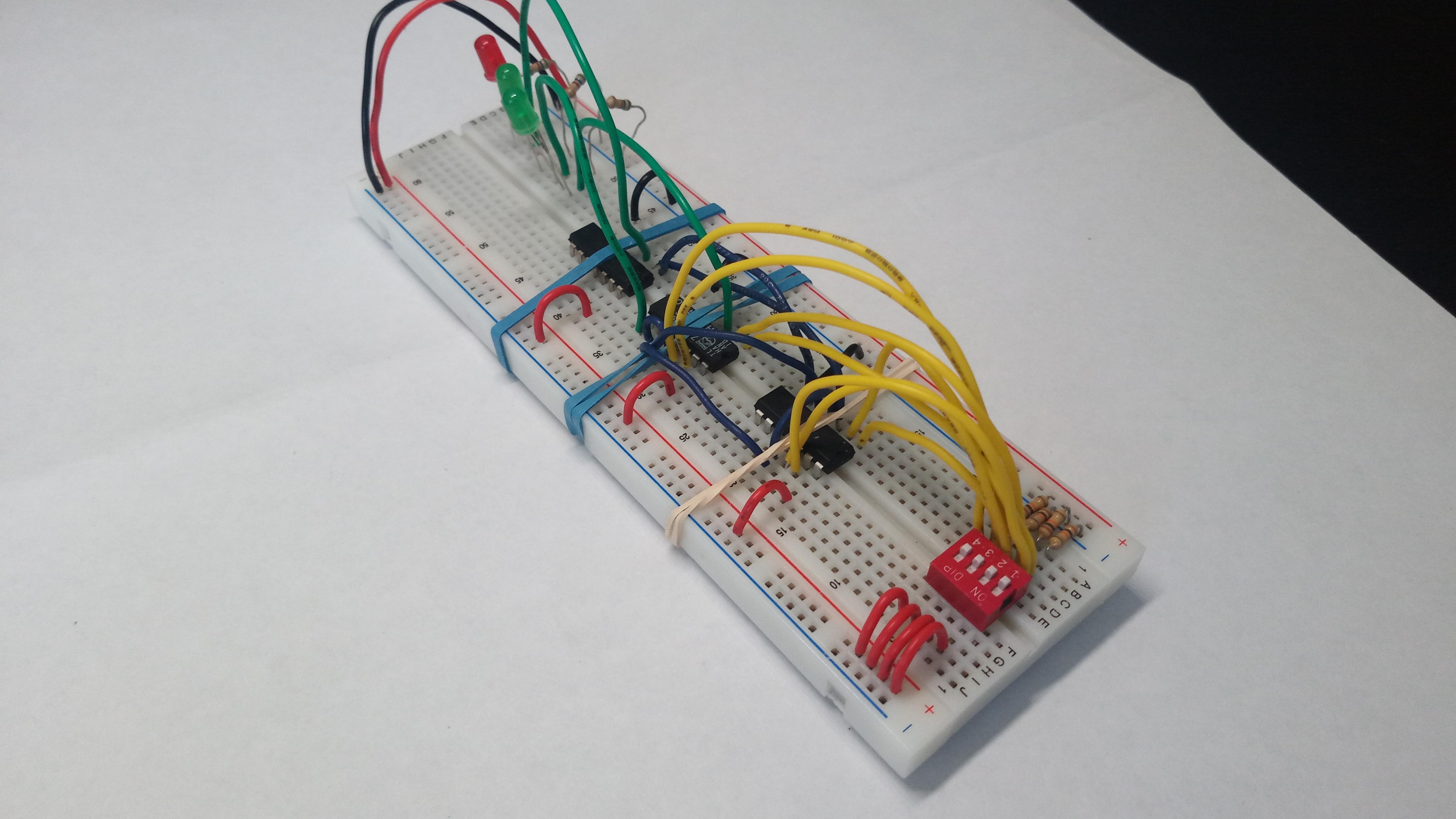
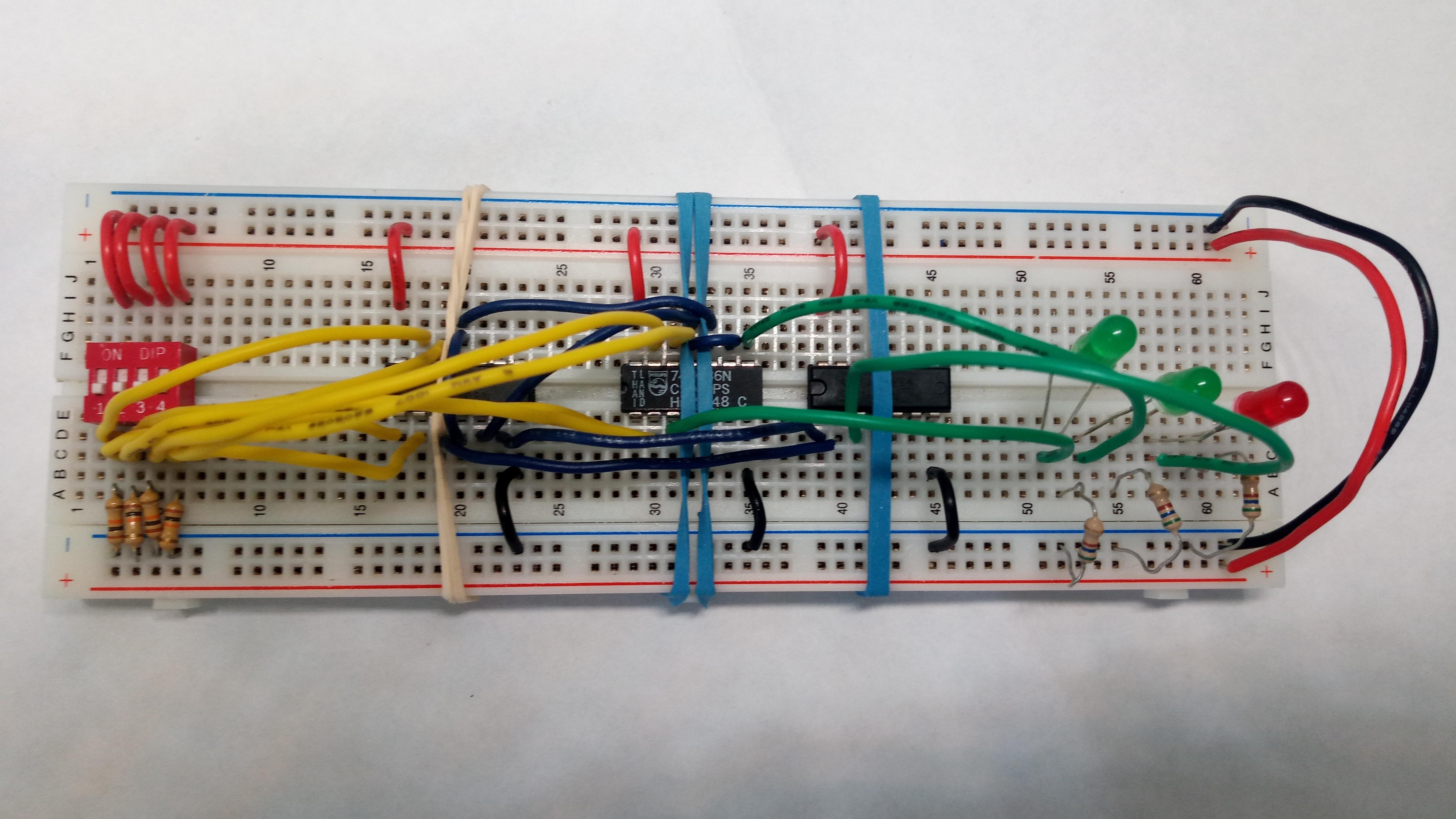
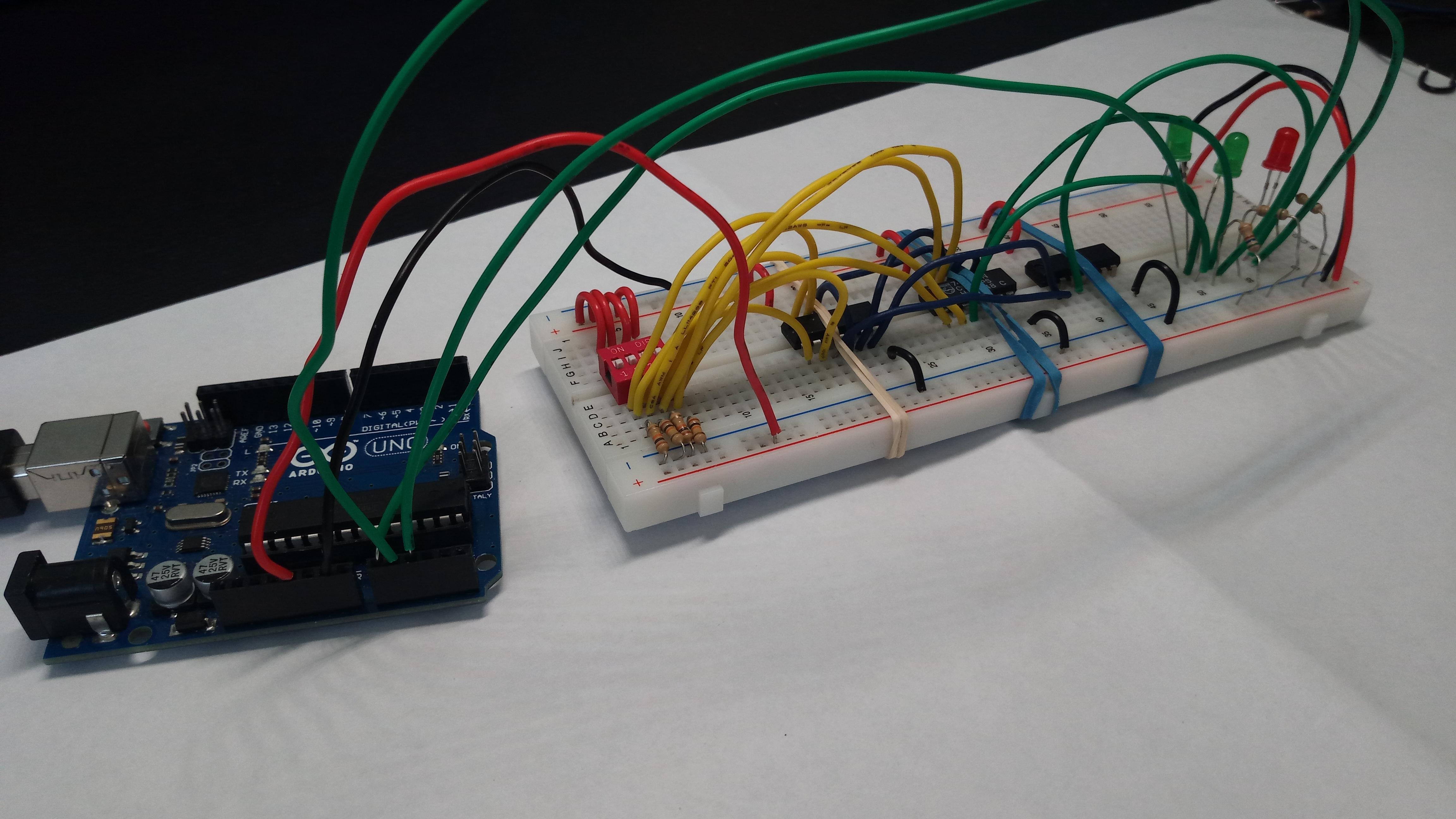
1. Once the 2-bit adder circuit has been completely built, you must test it.
2. Connect the Adder circuit to power and ground, to ensure it's working properly.
3. You will know it's working properly if the LEDs blink by following the pattern of the schematic, and TinkerCad circuit.
Once tested, begin the second phase.
Let’s Build the Hardware: Output Devices - 7 Segment Display & Buzzer
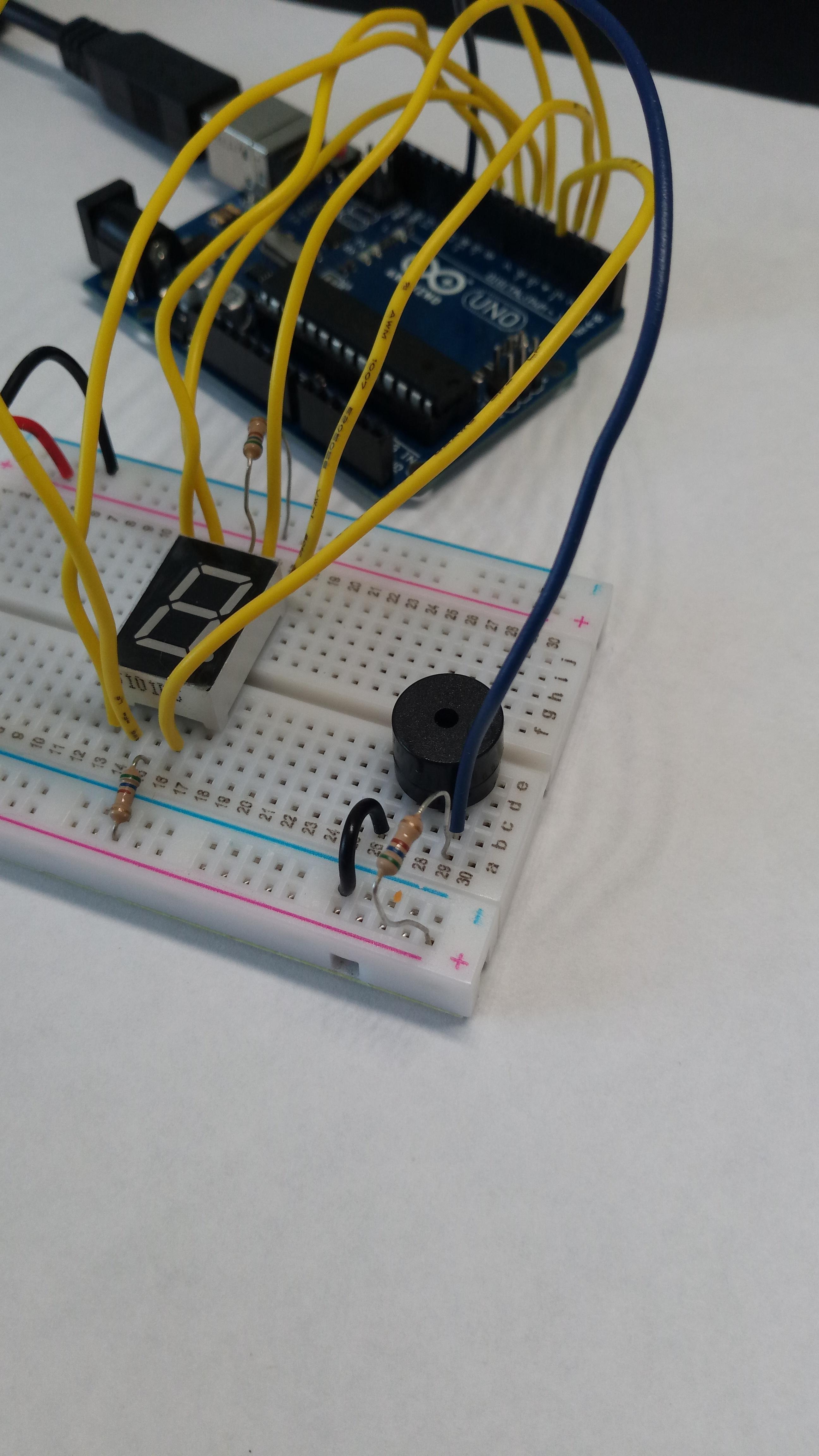
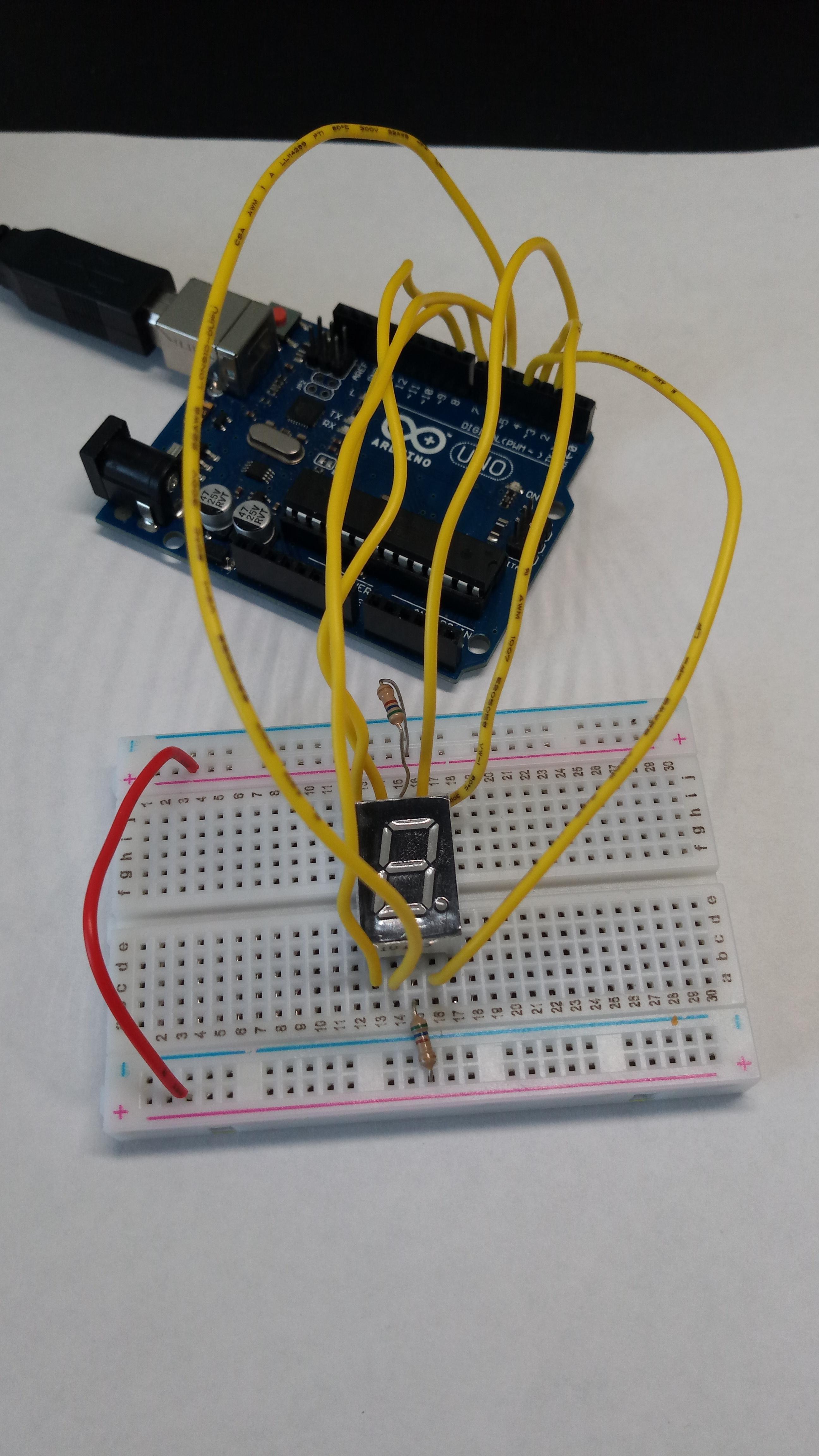
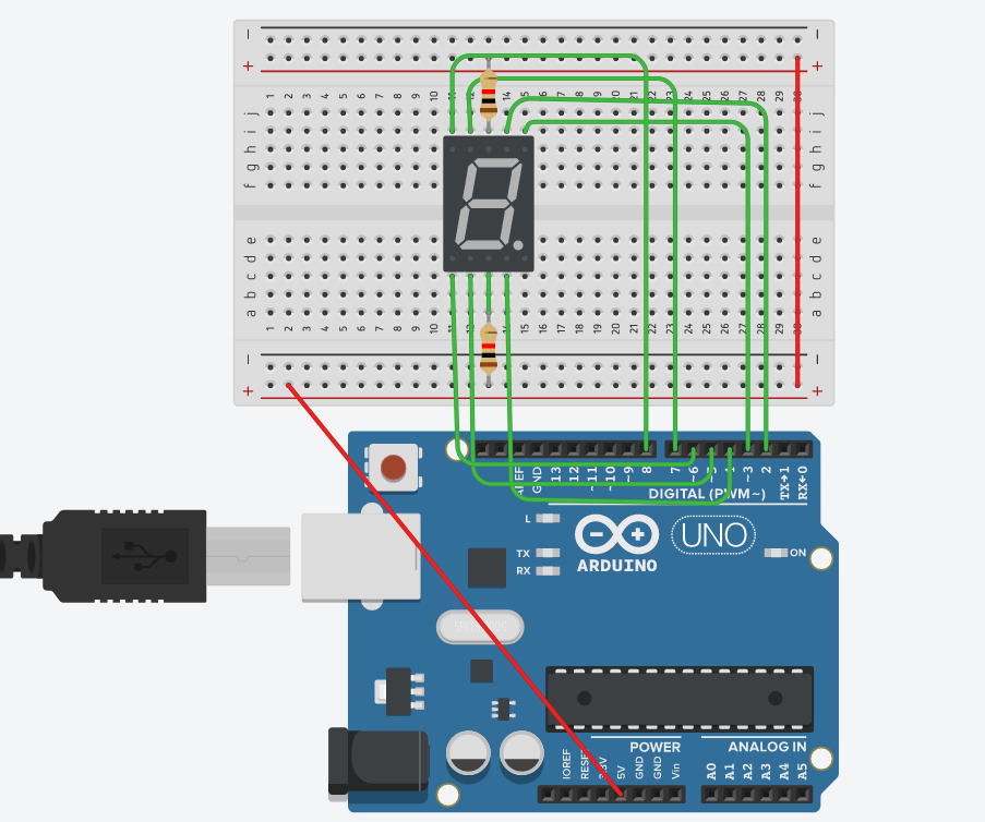
1. Add the 7 segment display to a small breadboard. (You can attach it to the large breadboard with the adder if you prefer- although space may be tight).
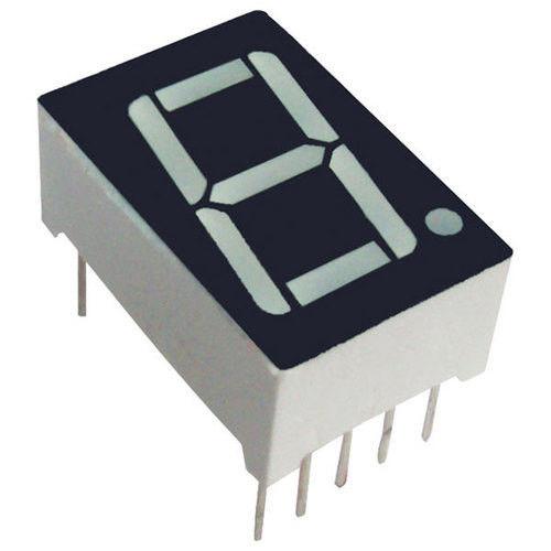
You might have seen the 7 segment display before. That's because it has been used in various devices, such as digital clocks. The display has 7 LEDs, named from a to g. It has 10 pins, which each turns a segment on (LOW) or off (HIGH), except for the common pins.
The display I am using is analog, meaning all of the anodes are connected together.
2. Connect the top and bottom middle pins of the display to power. Connect the remaining pins to the Digital PWM- with the exception of the bottom pin on the right. --- Ensure you know which pin is going into each pin of the Arduino Board. This info will be used during the coding.
I have attached an image that will assist you.
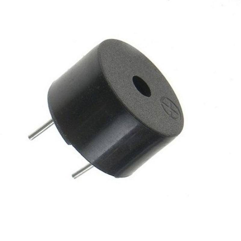
3. Attach a buzzer to the small breadboard. Wire positive terminal to power along with a 270Ω resistor, and negative terminal to ground. Attach the positive rail to any digital pin on the Arduino Board (I chose 11).
Let’s Write the Software: About the Code


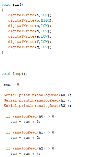
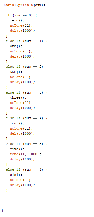
Copy the code (Refer to the next section) onto the Arduino IDE. (ATTACH Link to code), and upload to the hardware using the USB cable.
- The code is directing the 7 segment display to output a decimal value based upon the binary values of the LEDs.
- The code is dictating when the buzzer will sound. In my circuit's case, it will ring when the display shows a 5.
I have included additional descriptions in the code to help you understand each line.
Let’s Write the Software: the Code
//grade 12 summative assignment – Sonya Singh, JASS
//name each Arduino pin to be used in this simulation
int a = 2;// a to g used for the single digit display, each representing a separate bar in the digit 8 (7 in total)
int b = 3;
int c = 4;
int d = 5;
int e = 6;
int f = 7;
int g = 8;
int sum = 0;// used for adder
int buzzer = 11;//used for buzzer
//set program script
void setup()
//define I/O status of each pin – in this case all are output
{
pinMode(buzzer, OUTPUT);
Serial.begin(9600);// This passes the value 9600 to the speed parameter. This tells the Arduino to get ready to exchange messages with the Serial Monitor at a data rate of 9600 bits per second. That's 9600 binary ones or zeros per second, and is commonly called a baud rate pinMode(a, OUTPUT);
pinMode(b, OUTPUT);
pinMode(c, OUTPUT);
pinMode(d, OUTPUT);
pinMode(e, OUTPUT);
pinMode(f, OUTPUT);
pinMode(g, OUTPUT);
}
//define each digit from 0-6. High represents OFF and Low represents ON for each bar between a-g
// run calculations to convert led signals (Binary) to a digital number
void loop(){
// set starting value as zero
sum = 0;
// define analog pins A0-A2 as read. They are already input so no need to define them as I/O
// Serial.Println prints data to the serial port as human-readable ASCII text followed by a carriage return character (ASCII 13, or '\r') and a newline character (ASCII 10, or '\n'), in this case it reads the analog input on pin A0-2
Serial.println(analogRead(A0));
Serial.println(analogRead(A1));
Serial.println(analogRead(A2));
//establish
if (analogRead(A0) > 0)
sum = sum + 1;
if (analogRead(A1) > 0)
sum = sum + 2;
if (analogRead(A2) > 0)
sum = sum + 4;
//to display the digital equivalent value on the monitor
//call out the equivalent sub program (Void) base on sum (e.g. if sum = 0, run the digital 0 generator script)
//Add buzzer feature, to turn on when the total is 5
Serial.println(sum);
if (sum == 0) {
zero();
noTone(11);//use notone to mute the buzzer for all non-5 numbers
delay(1000);
}
else if (sum == 1) {
one();
noTone(11);
delay(1000);
}
else if (sum == 2) {
two();
noTone(11);
delay(1000);
}
else if (sum == 3) {
three();
noTone(11);
delay(1000);
}
else if (sum == 4) {
four();
noTone(11);
delay(1000);
}
else if (sum == 5) {
five();
tone(11, 1000); //use tone to ring the buzzer when display reads 5
delay(1000);
}
else if (sum == 6) {
six();
noTone(11);
delay(1000);
}
//close program scirpt
}
Let's See It in Action: Final Testing and Troubleshooting
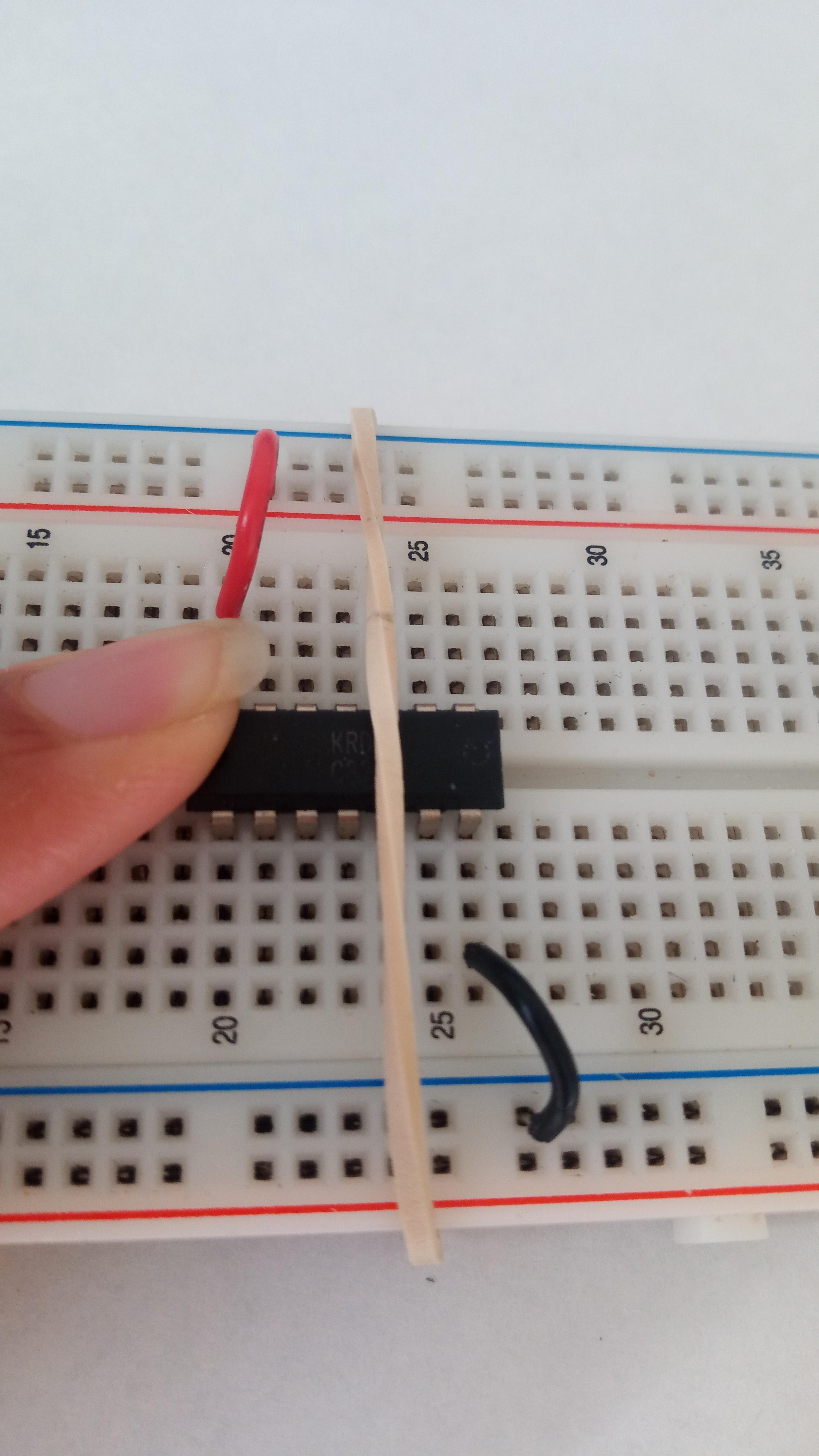
After I completed the build of the hardware and software, I ran a final test of the software simulation and addressed some of the common issues that appeared.
- Loose cables needed to be reattached to the breadboard and Arduino pins.
- IC circuits kept popping out, so I fastened in place using rubber bands.
- Replaced the wires with longer segments to facilitate mobility.
- Check LEDs to make sure they were functional.
- Recode where needed, e,g, If the buzzer was too loud.
Let's See It in Action: the Movie
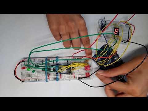
2 Bit Adder Calculator 1st Video
2-Bit Adder Calculator 2nd Video
Click on the link to view the video!
I hope you'll have fun building the adder, and including additional features!