Ultimaker 2, 1.75mm Conductive Filament Feeder Arm Design
by osdoyi in Workshop > 3D Printing
5935 Views, 12 Favorites, 0 Comments
Ultimaker 2, 1.75mm Conductive Filament Feeder Arm Design


Hello everyone,
I decided to 3D print conductive circuits with the 3D printer. When I buy conductive filament, I faced with a situation that feeder system of the Ultimaker series are not supporting 1.75 mm filaments. Buying new kits was expensive. So I decided to solve this problem for my big goal and come up with this instructable.
With a permission from our lab, I decided to open the current feeder system of the Ultimaker. The main problem was GRIPPING, the gap for the PLA material feeding was not providing enough friction force to push 1.75 mm filament up. Due to this fact, I decided to re-design / develop the most important part that Ultimaker feeder have. I decreased the filament gap that current design has. And 3D print the new part. (100% infill of course) Result was very impressive. Right now we can print with 1.75 mm filaments perfectly.
Follow the steps and built yours. Additionally in the last step I give .stl files for preparing the conductive circuit as well. Don't forget the watch the assembly and printing video that I prepare for this instructable.
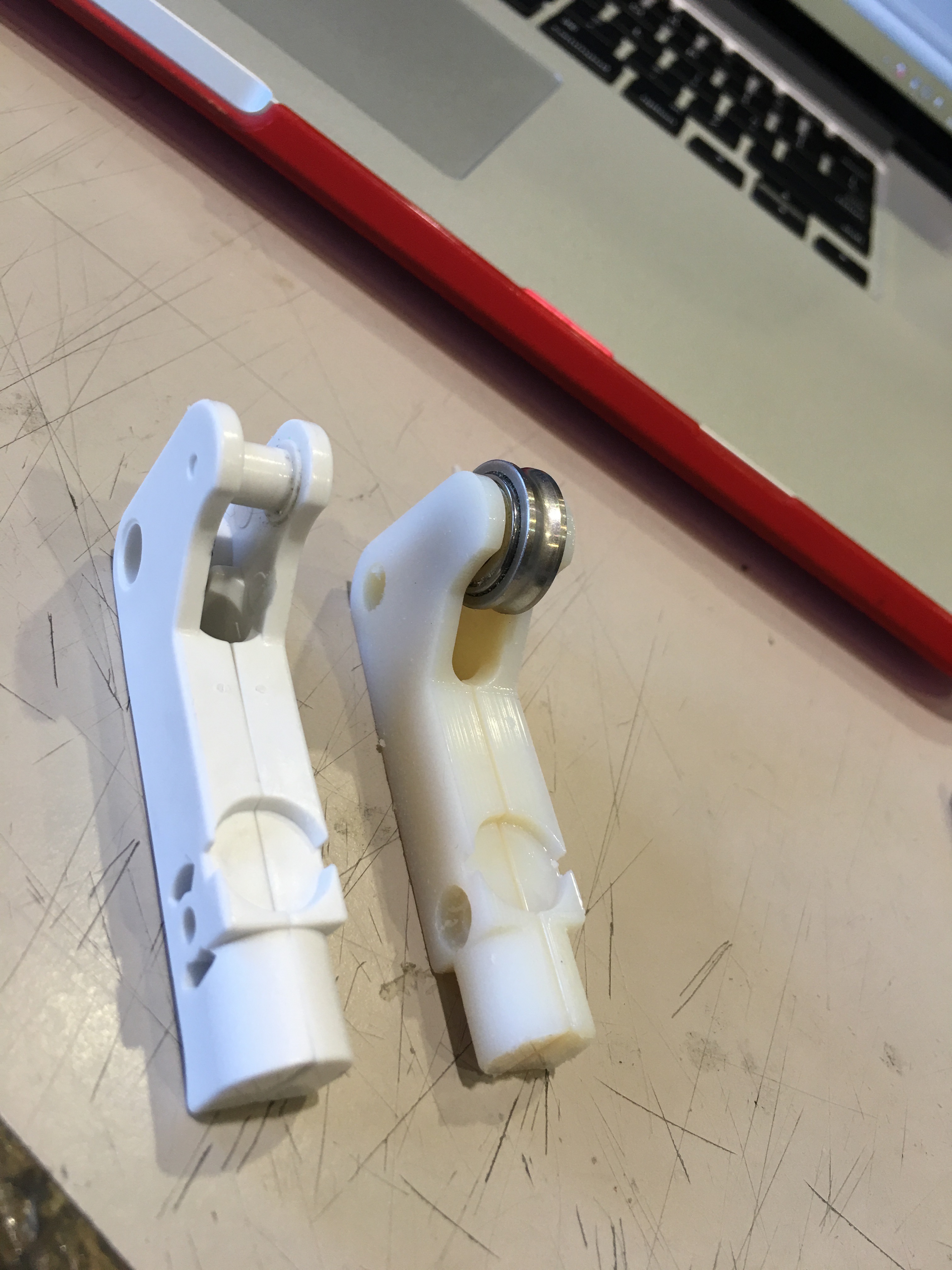
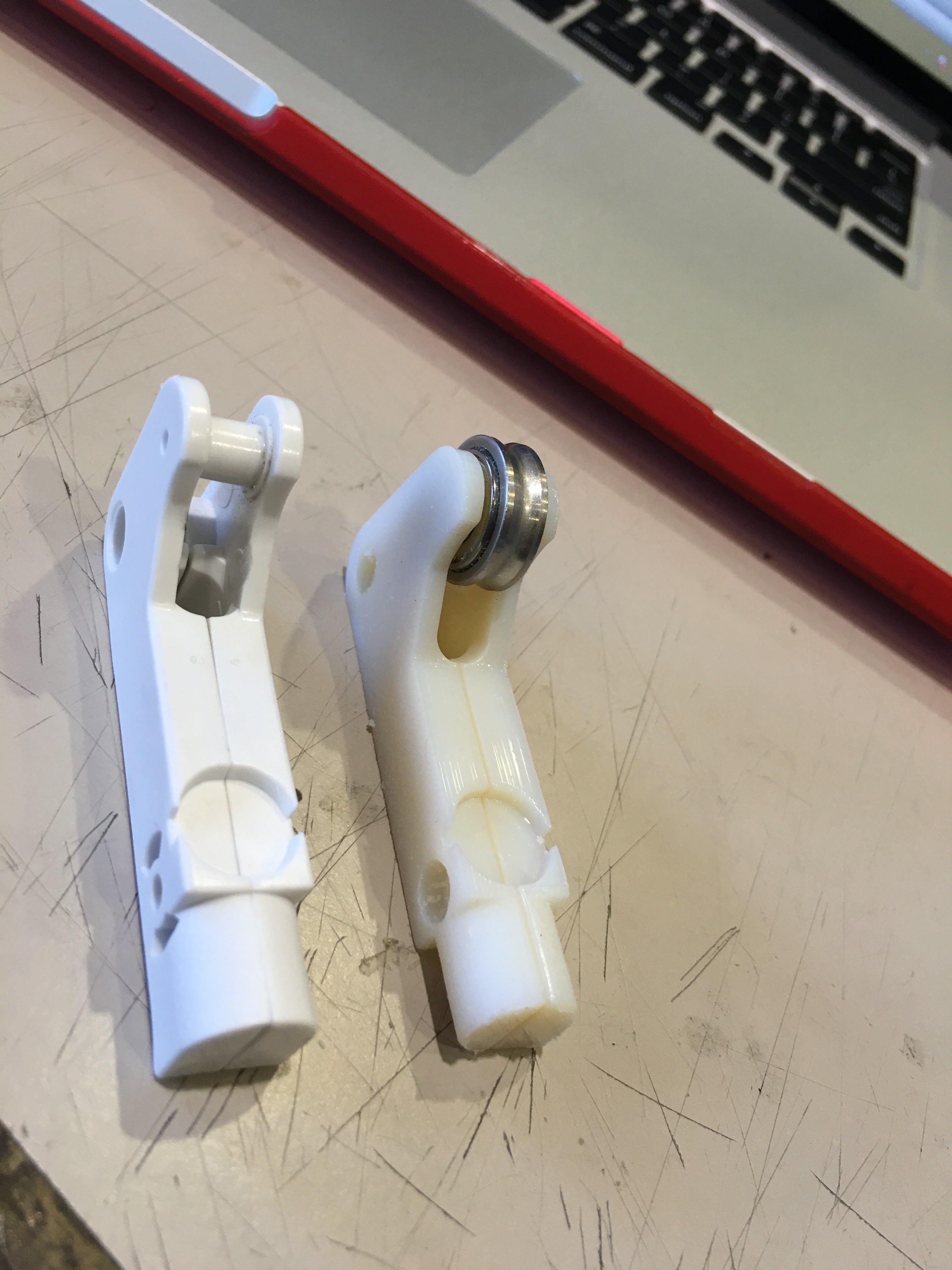
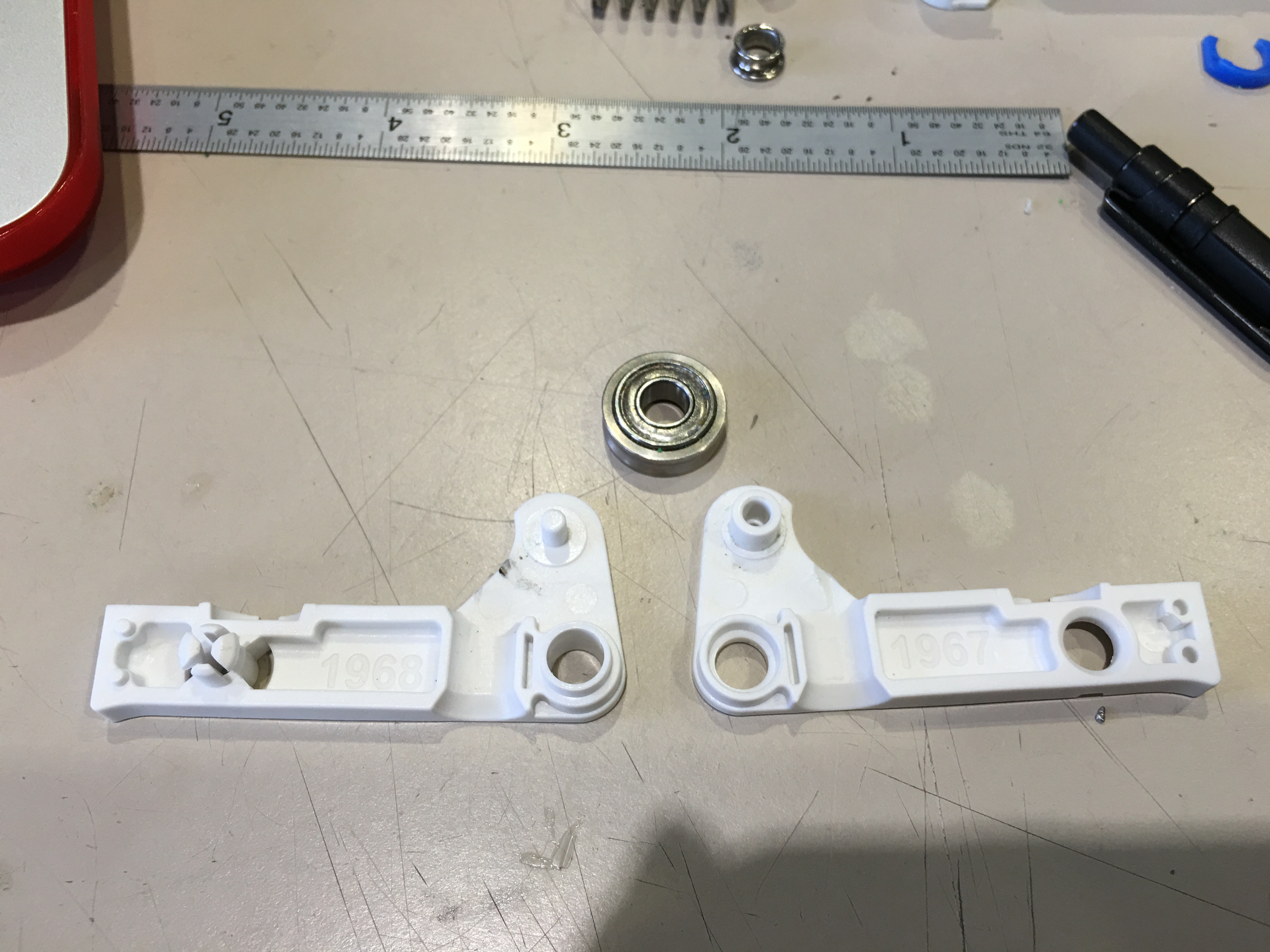
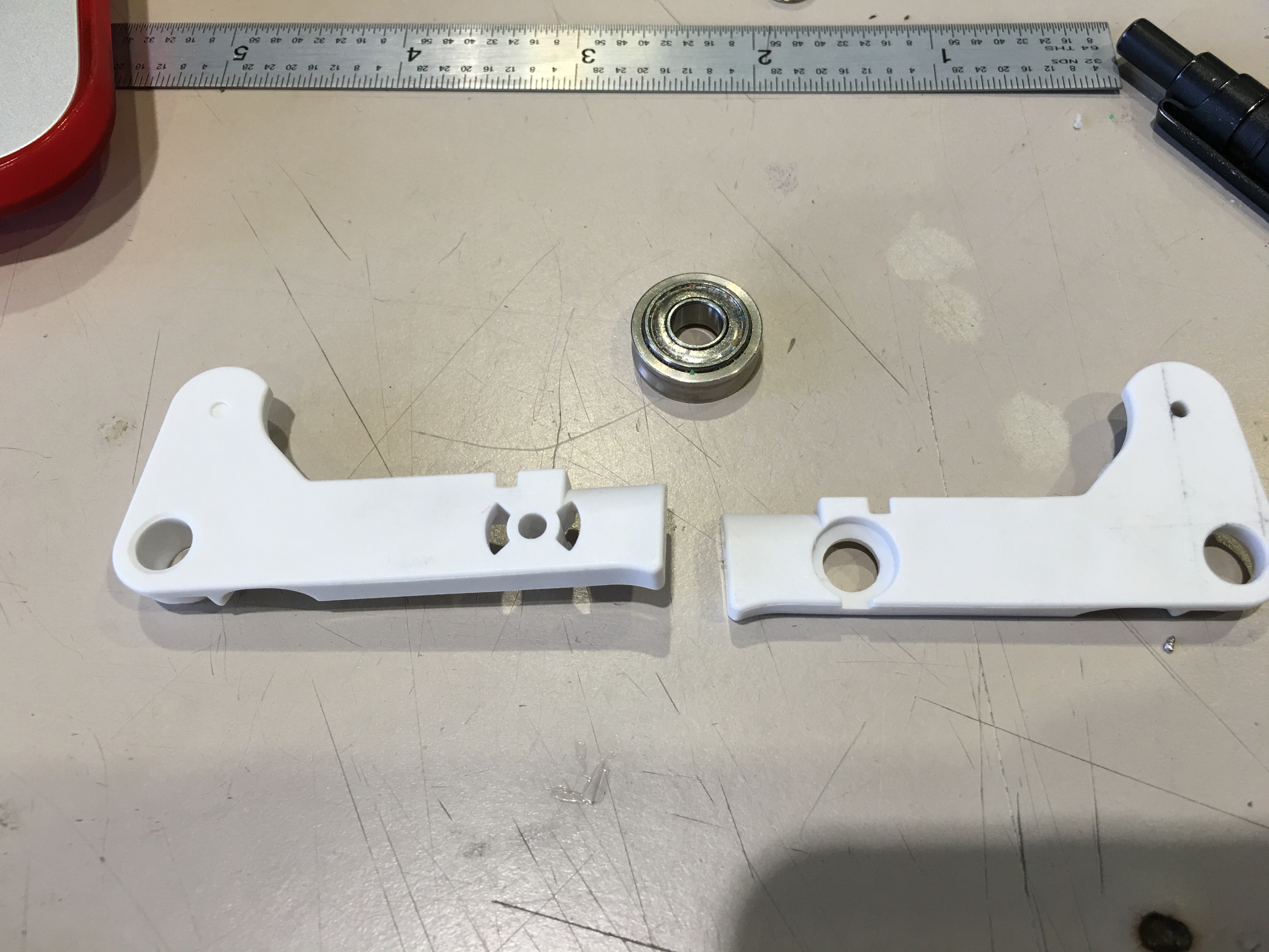
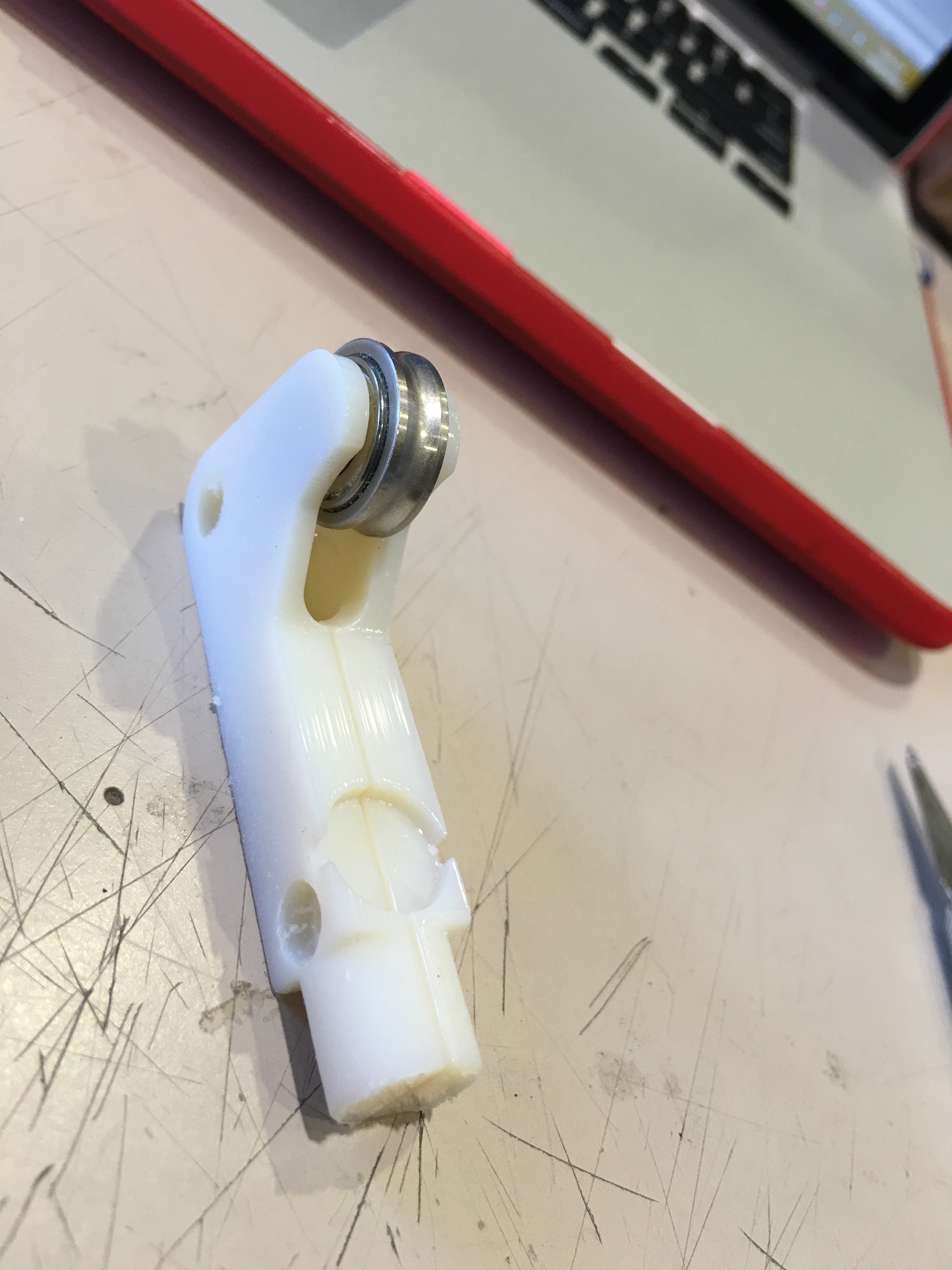
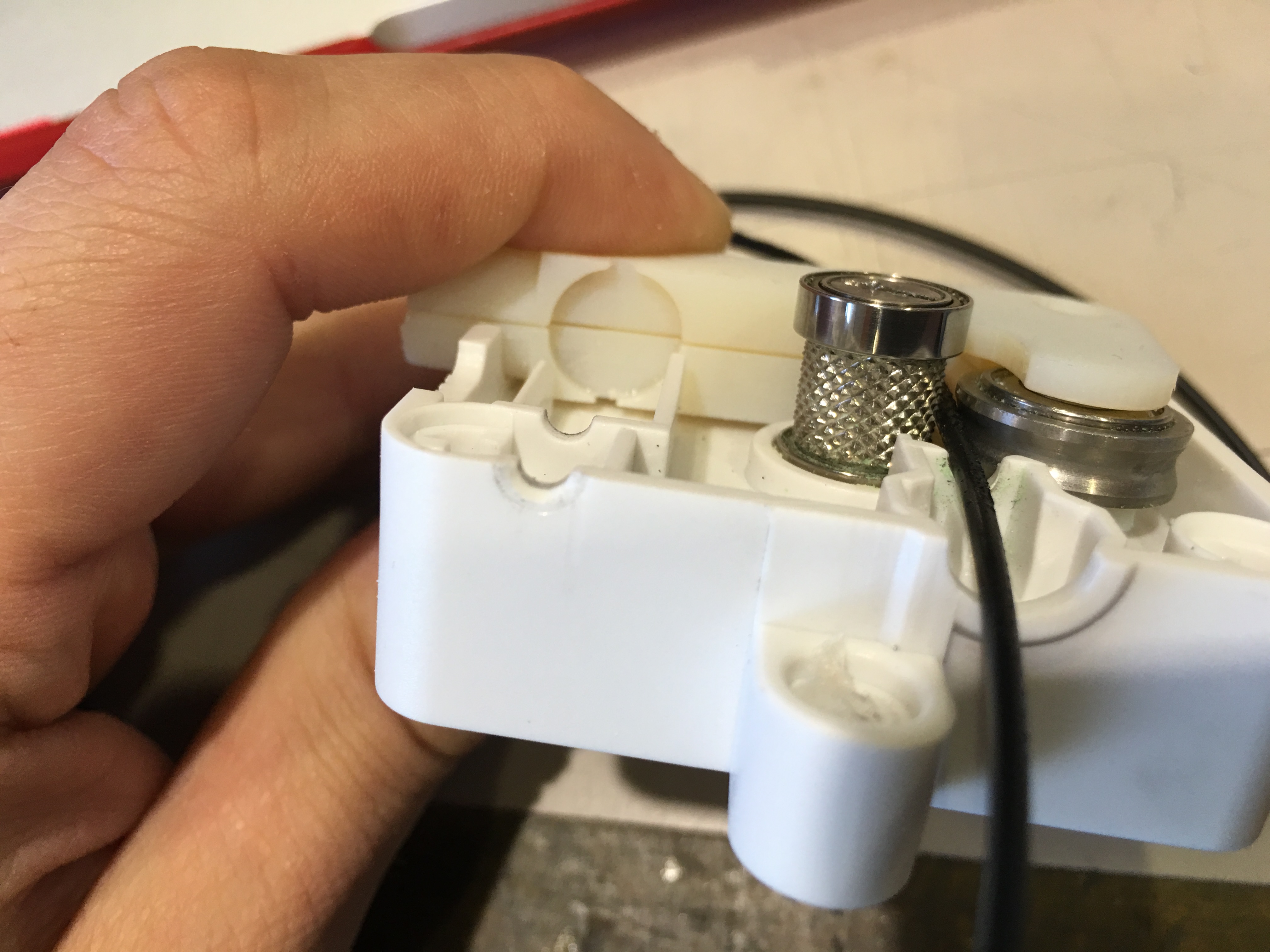
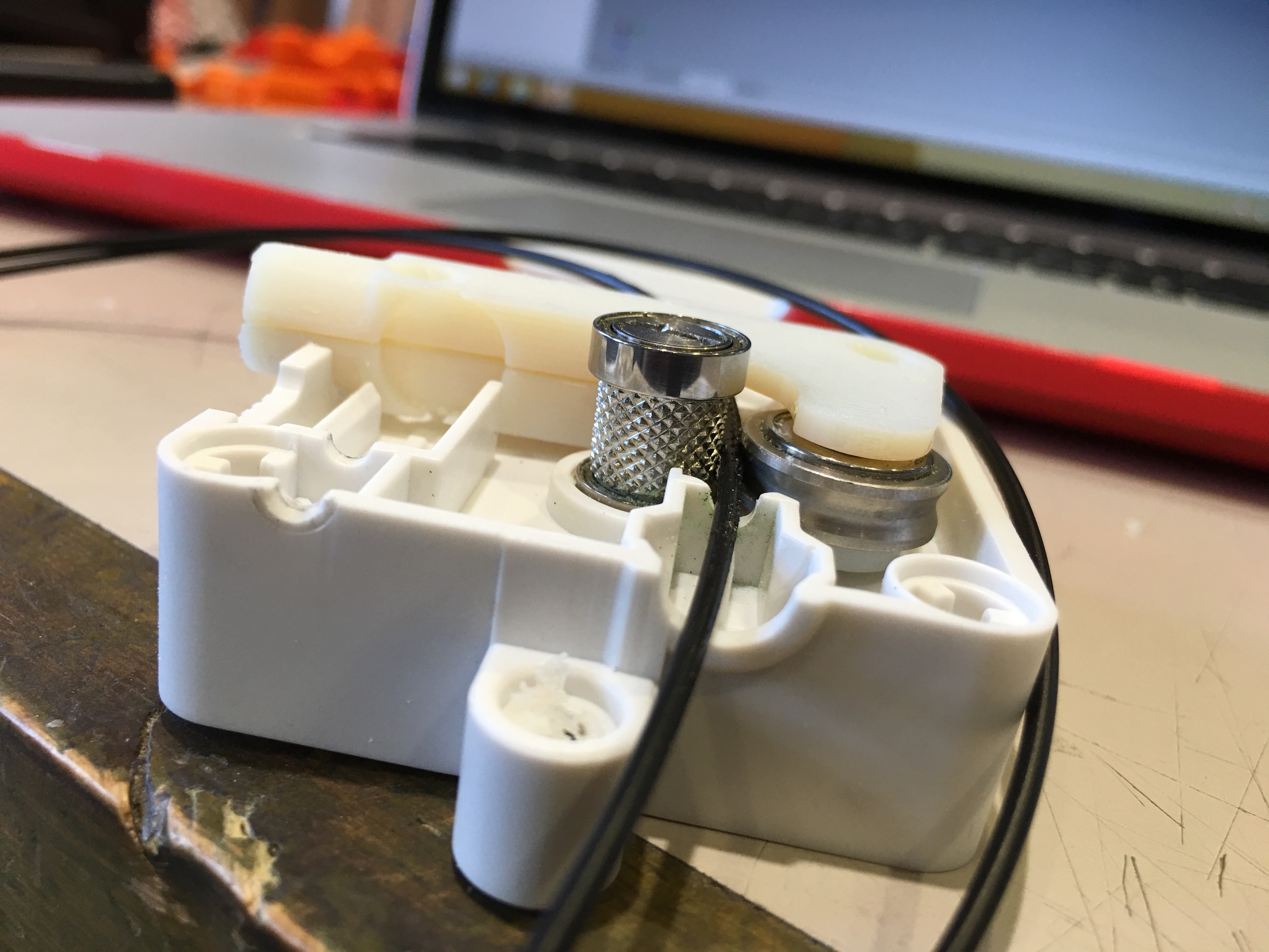
See the designed feeder arm from the pictures. It is beautiful :)
3D Printing Re-designed Part / Development of the Current Feeder System
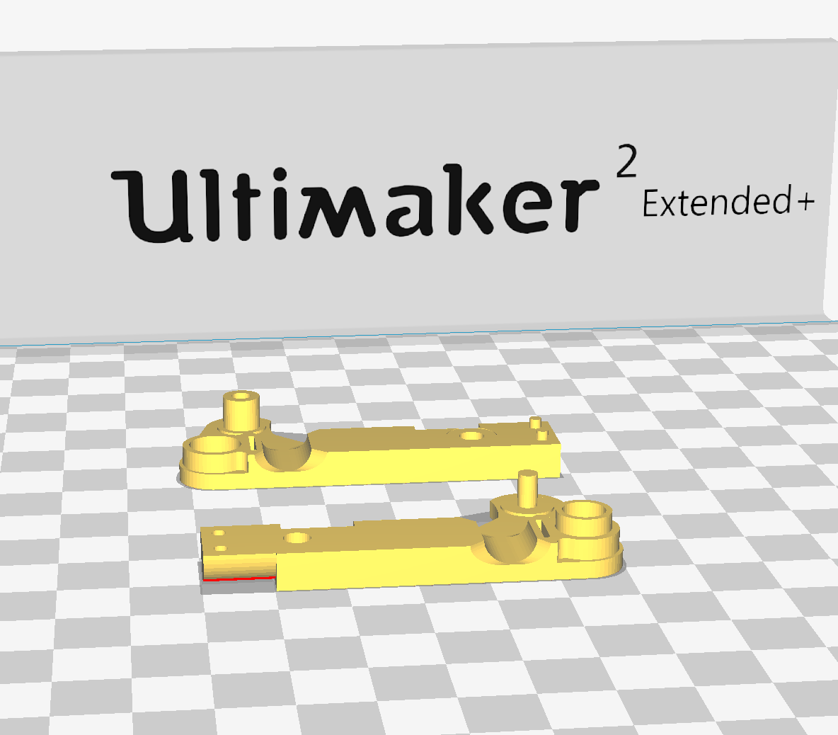


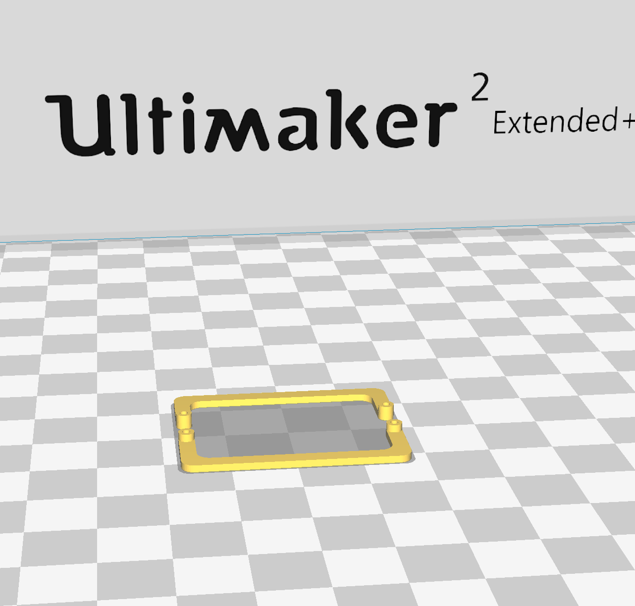
In this step, I am sharing my .stl files for you to be able to print the feeder arm design that I developed.
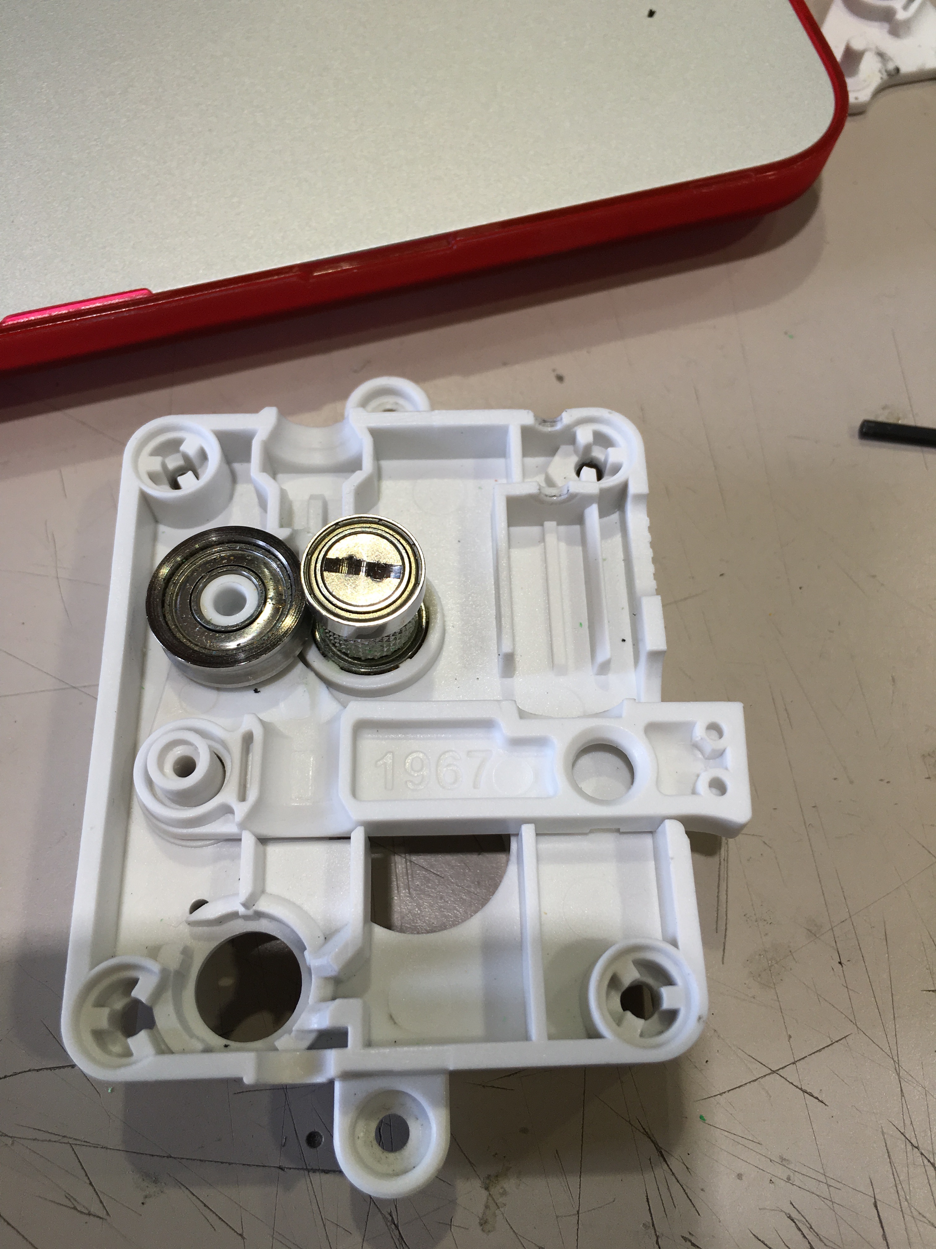
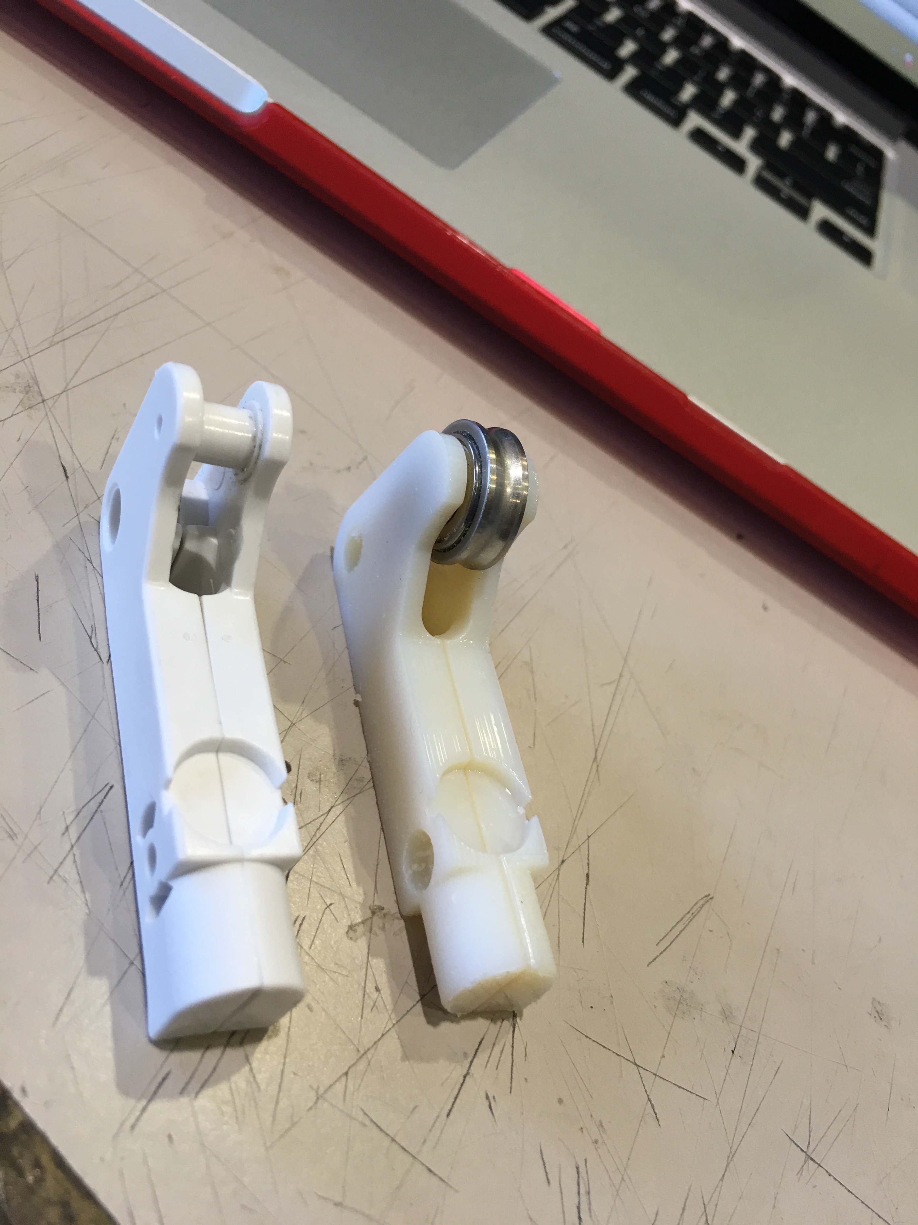
The difference between my design and current design is: the new design is holding the metal roller 1.3 mm closer to the metal part that is connected to the motor. See the pictures.
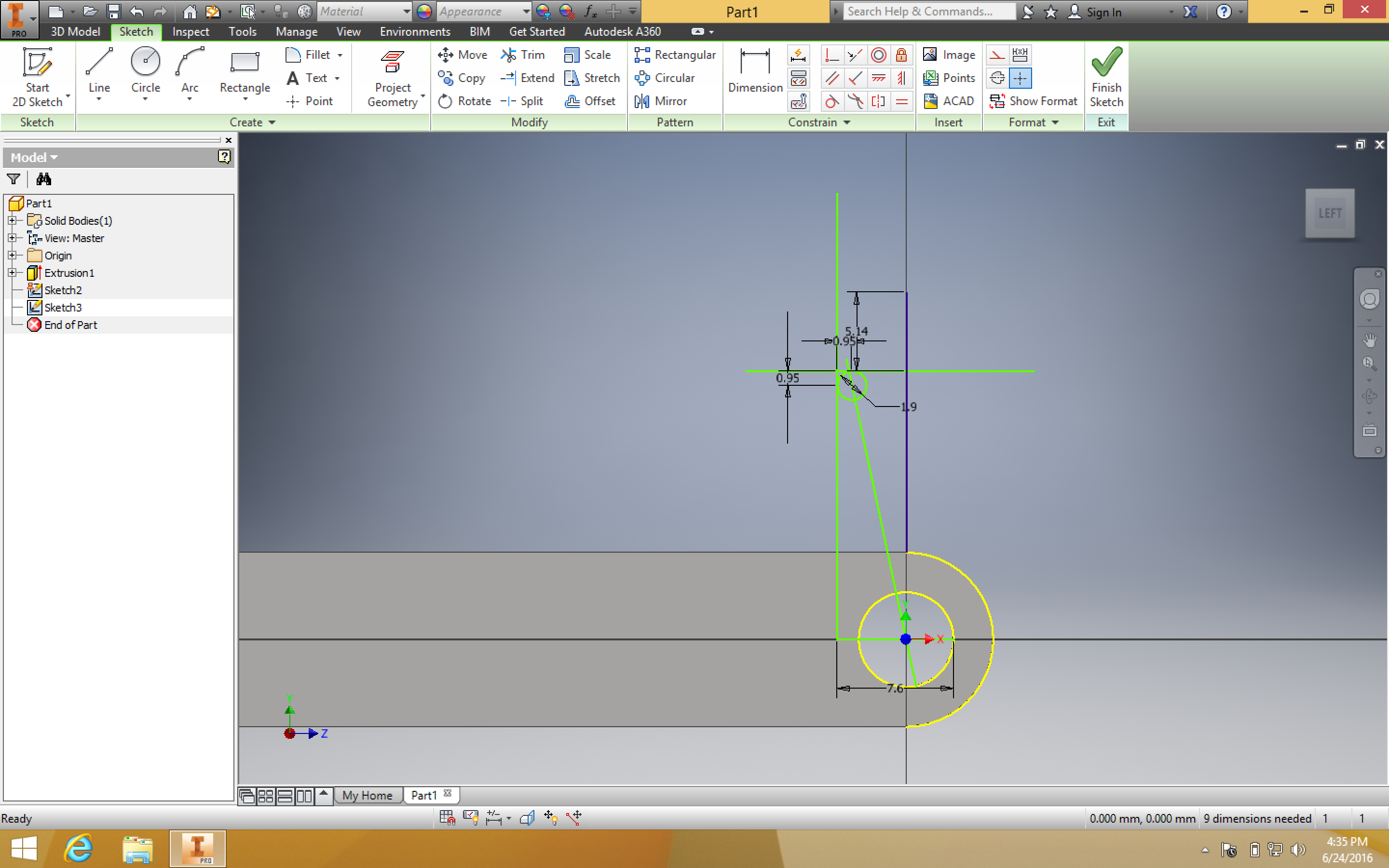
I developed this part on Autodesk inventor. By using caliper and rulers I measured the dimensions of existing part and change some dimensions.
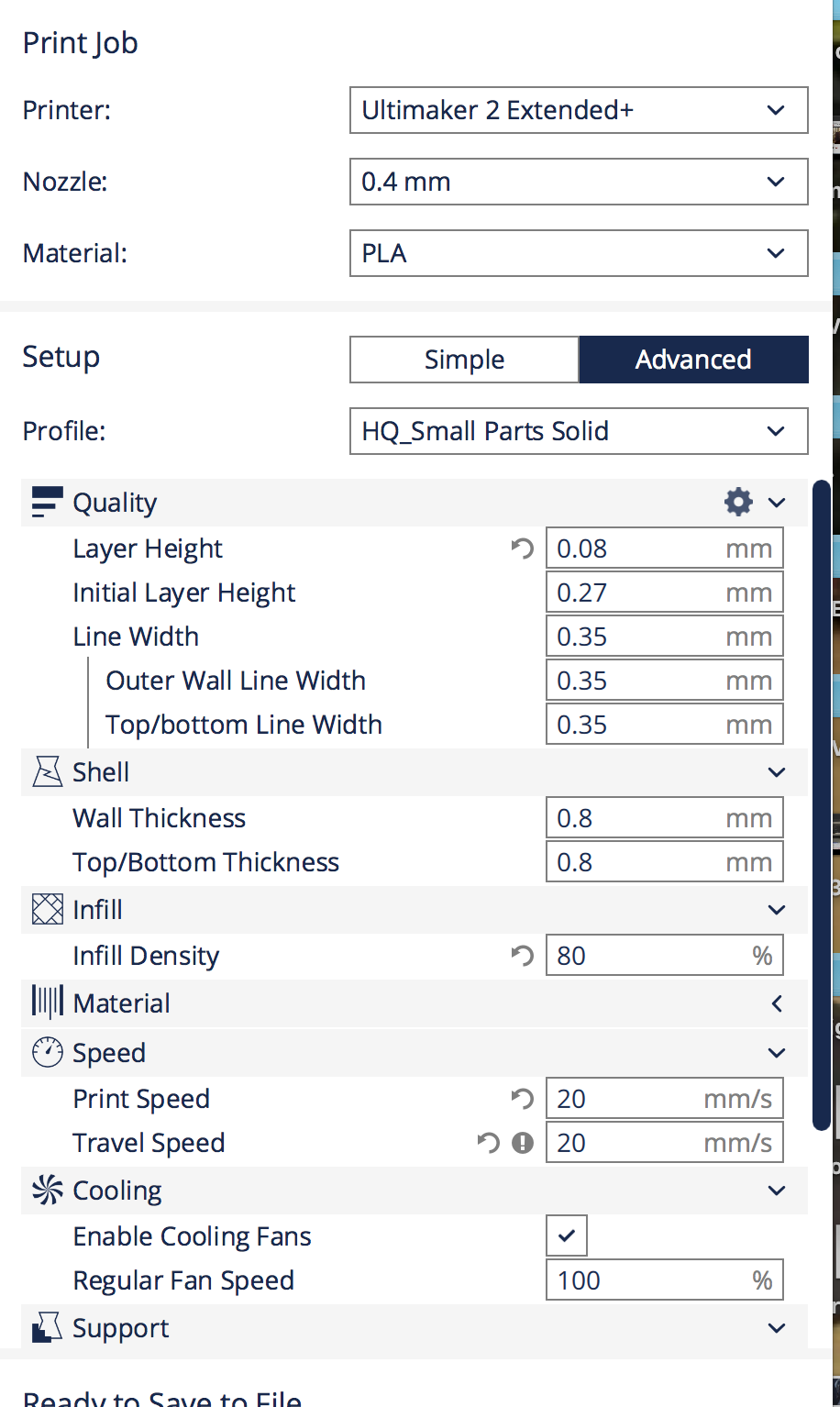
Additionally, please apply the same setting that I provide to print this developed part. Don't forget to use 100% infill. Otherwise your part may not be strong enough.
You can use 3D Hubs ( https://www.3dhubs.com) for printing this part, depends on the place it is pretty fast. I get permission to use one printer from our research lab.
Warning: While you are printing select the infill density: 100% otherwise your part may breake :/
Problems Without My Feeder Development
Problems without my feeder development,
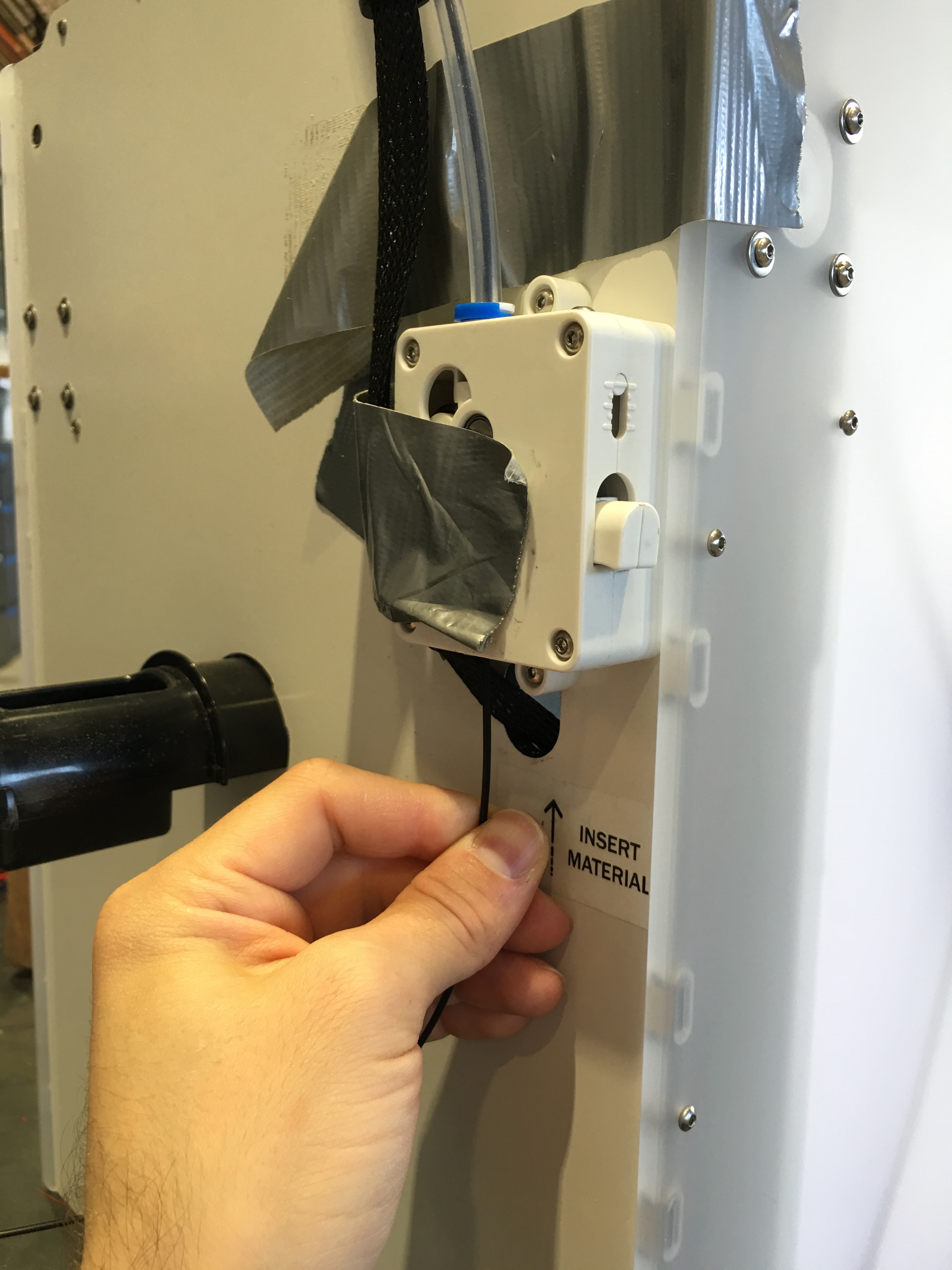
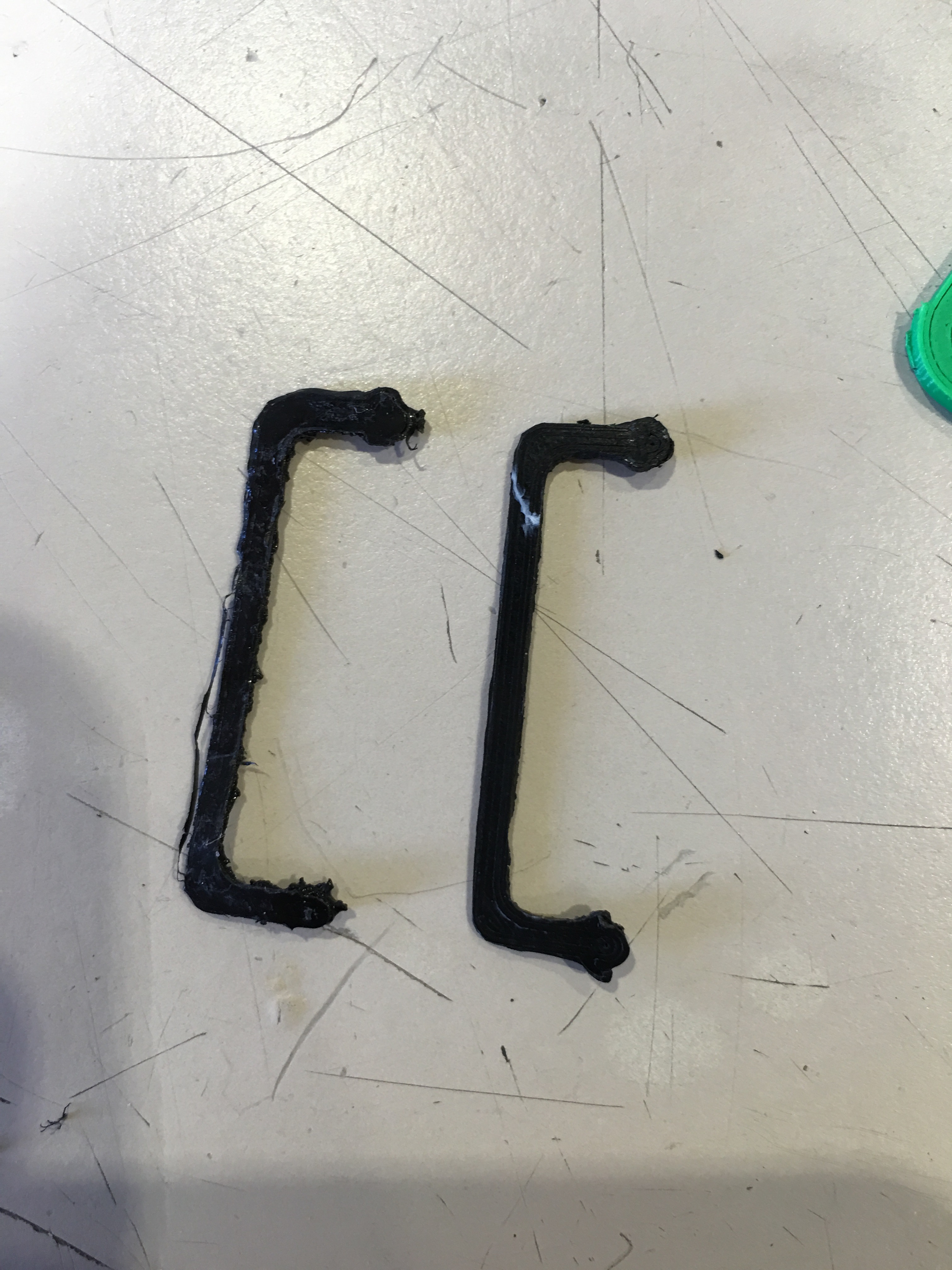
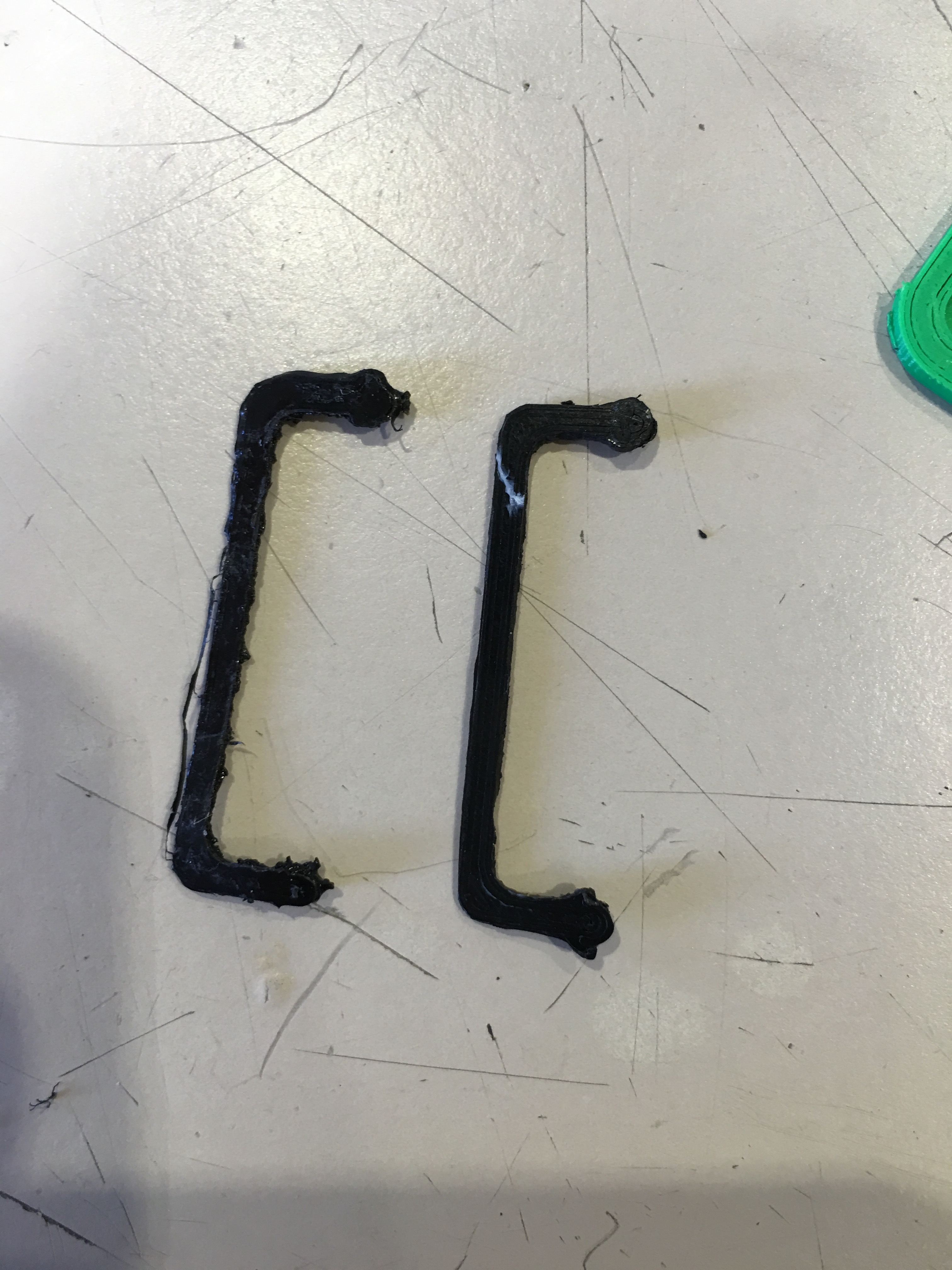
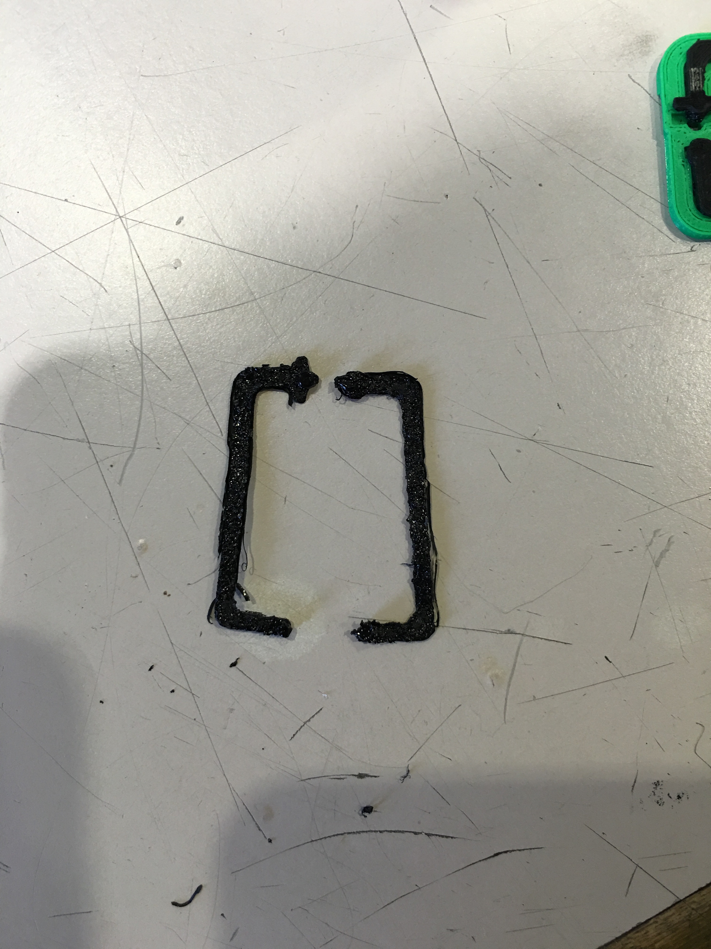
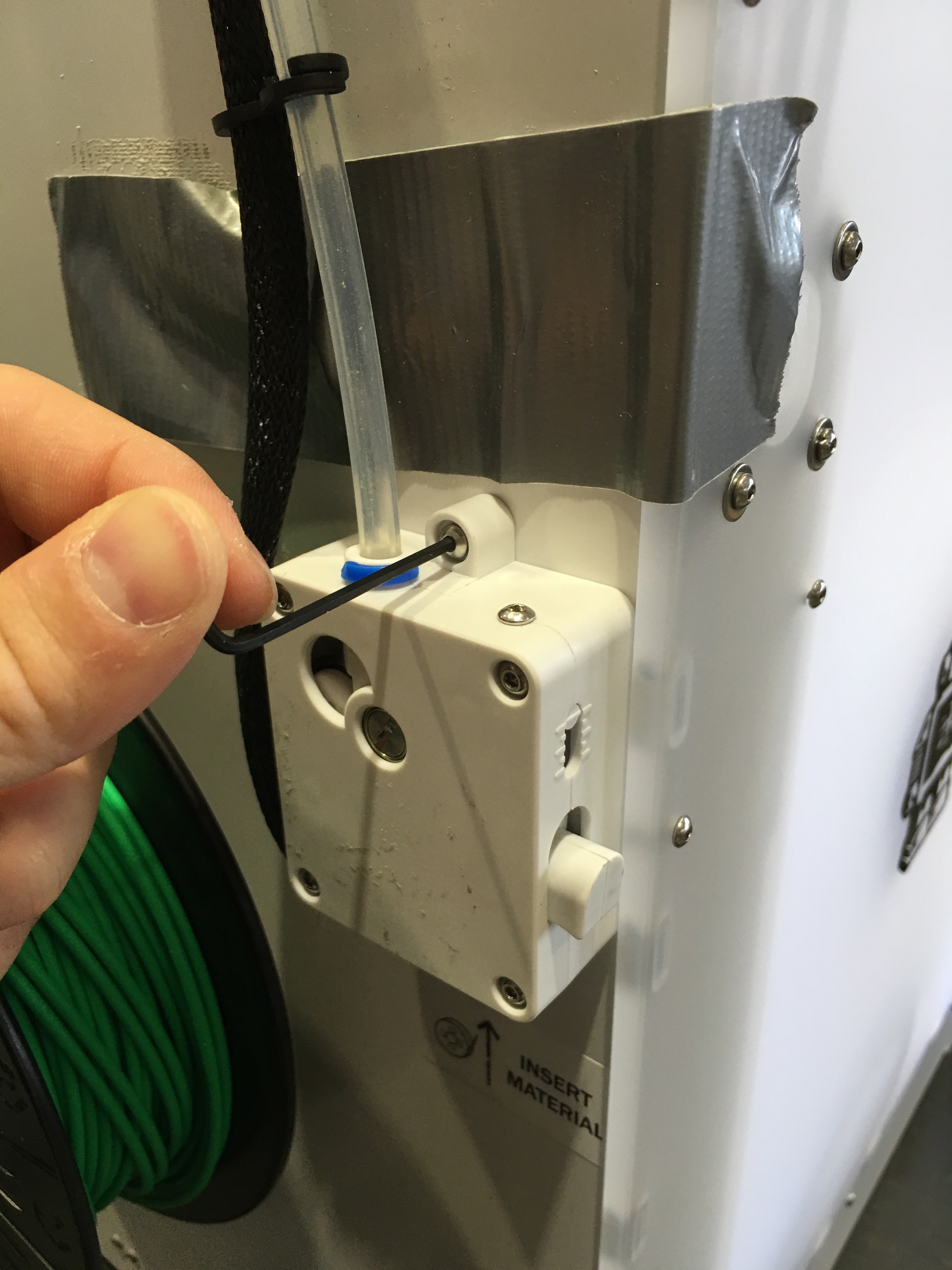
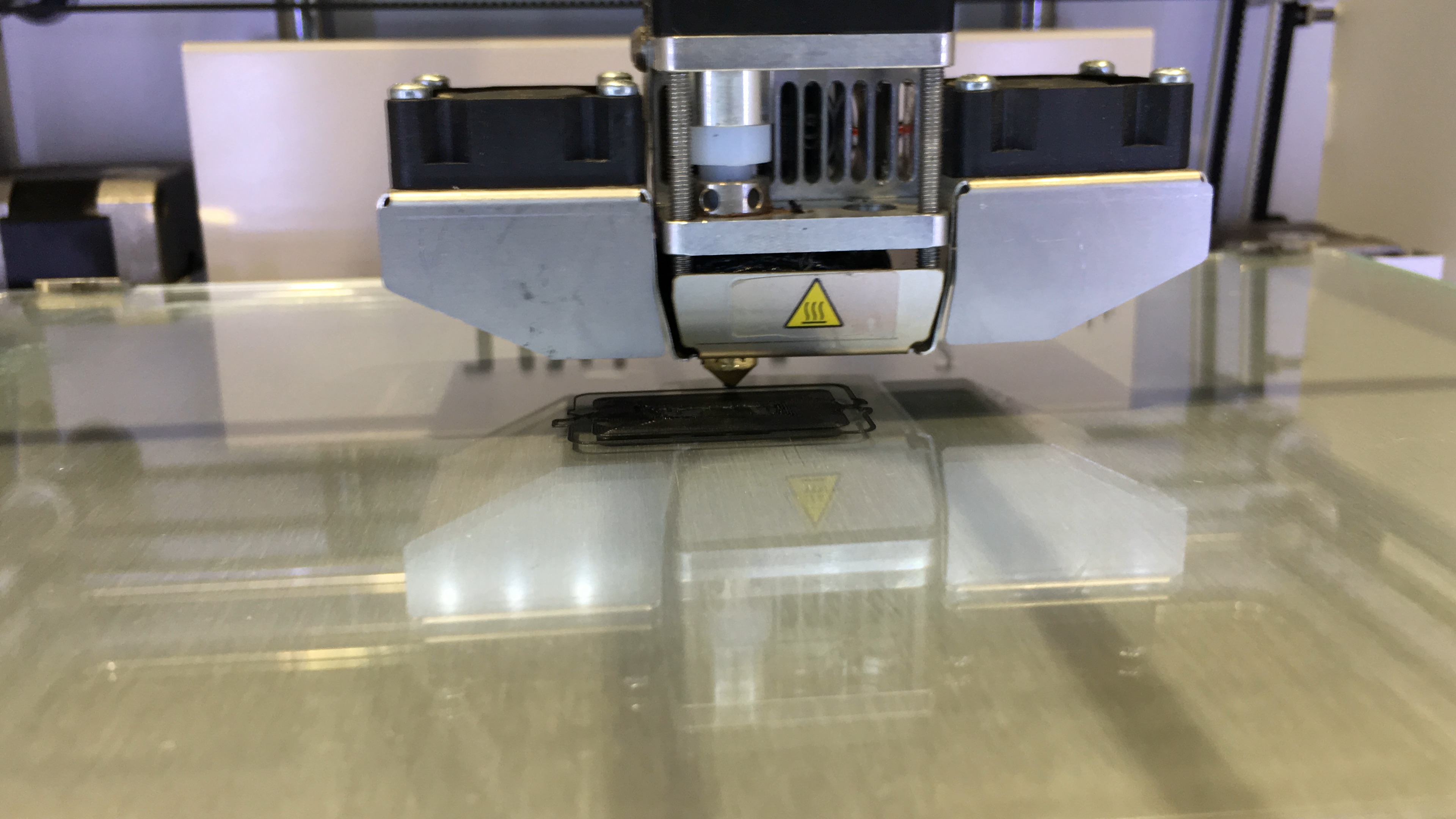
The main problem is slipping of the conductive PLA from the feeder when the system try to push it up. Due to this fact before developing this part I was trying to push it with my hand (see the picture). But for longer prints you don't have that much patience :). And please see the outputs. The printed parts were really bad. And nozzle was not able to print the material if you not push the material with your hand.
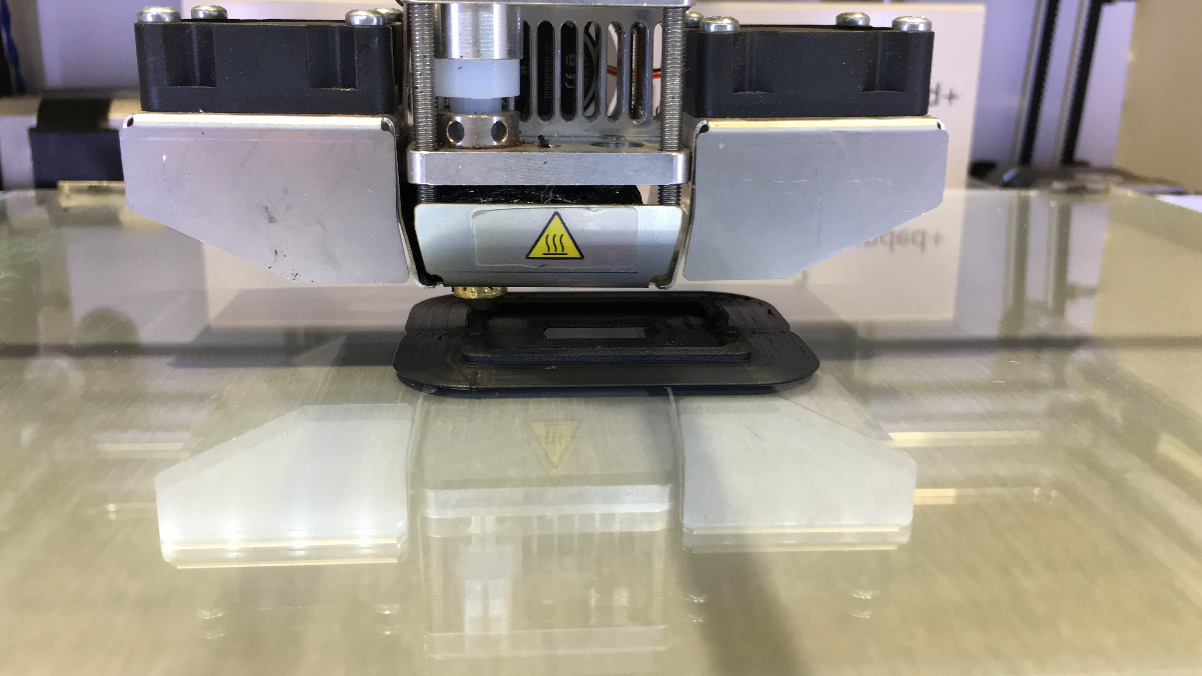
After developing the feeder arm, the result was amazing. See the last picture of my circuit and the lines. I am very impressed with the result. Check the next step for the assembly of the arm, then you will find more information about printing this circuit as well.
Assembling the New Feeder Arm Into Current Feeder System

To see the overall assembly steps and my moves, please watch the video. Also you can follow the pictures at this step as well.
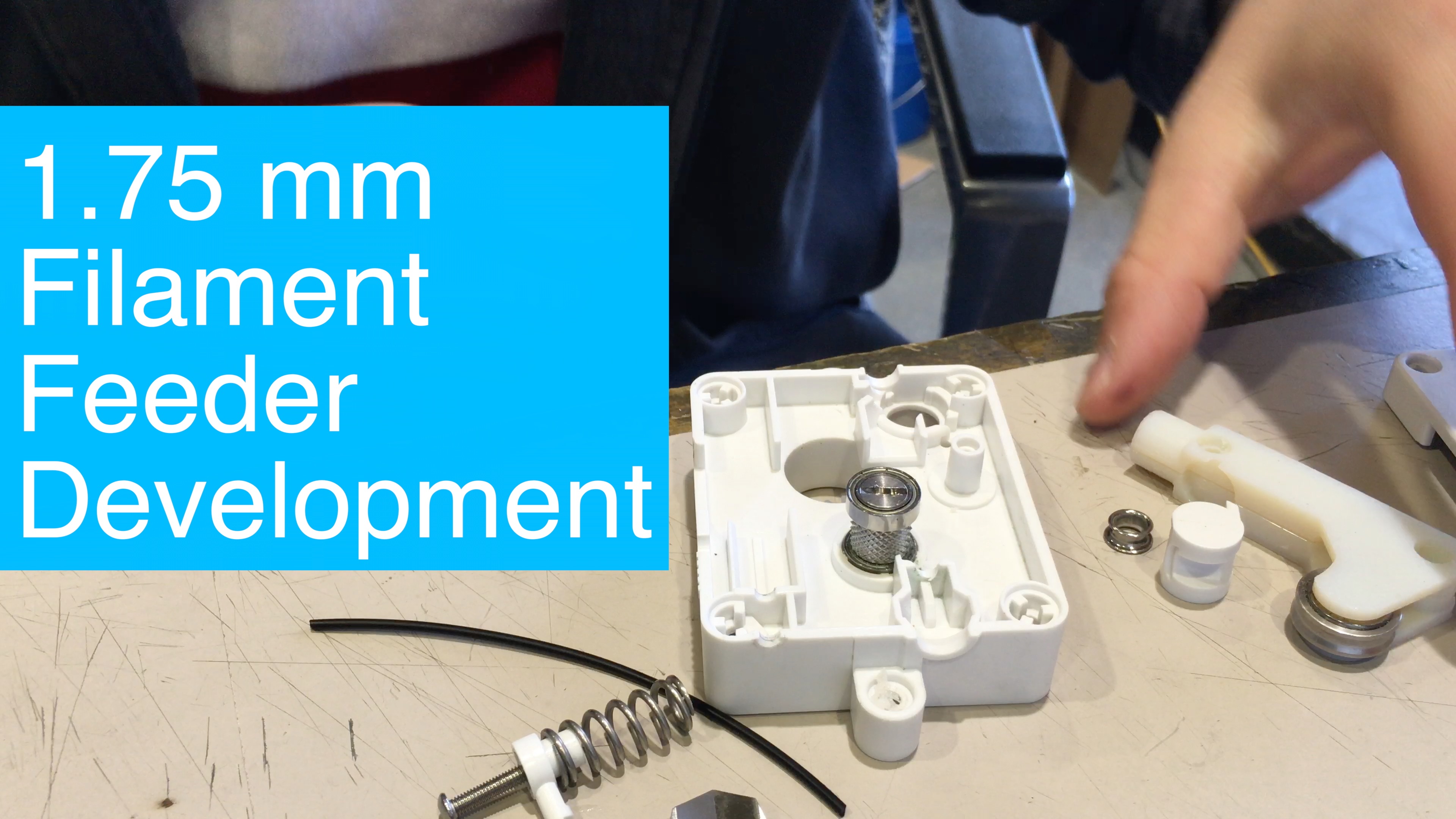
Here are the steps to assemble new 3D printed arm into current design:
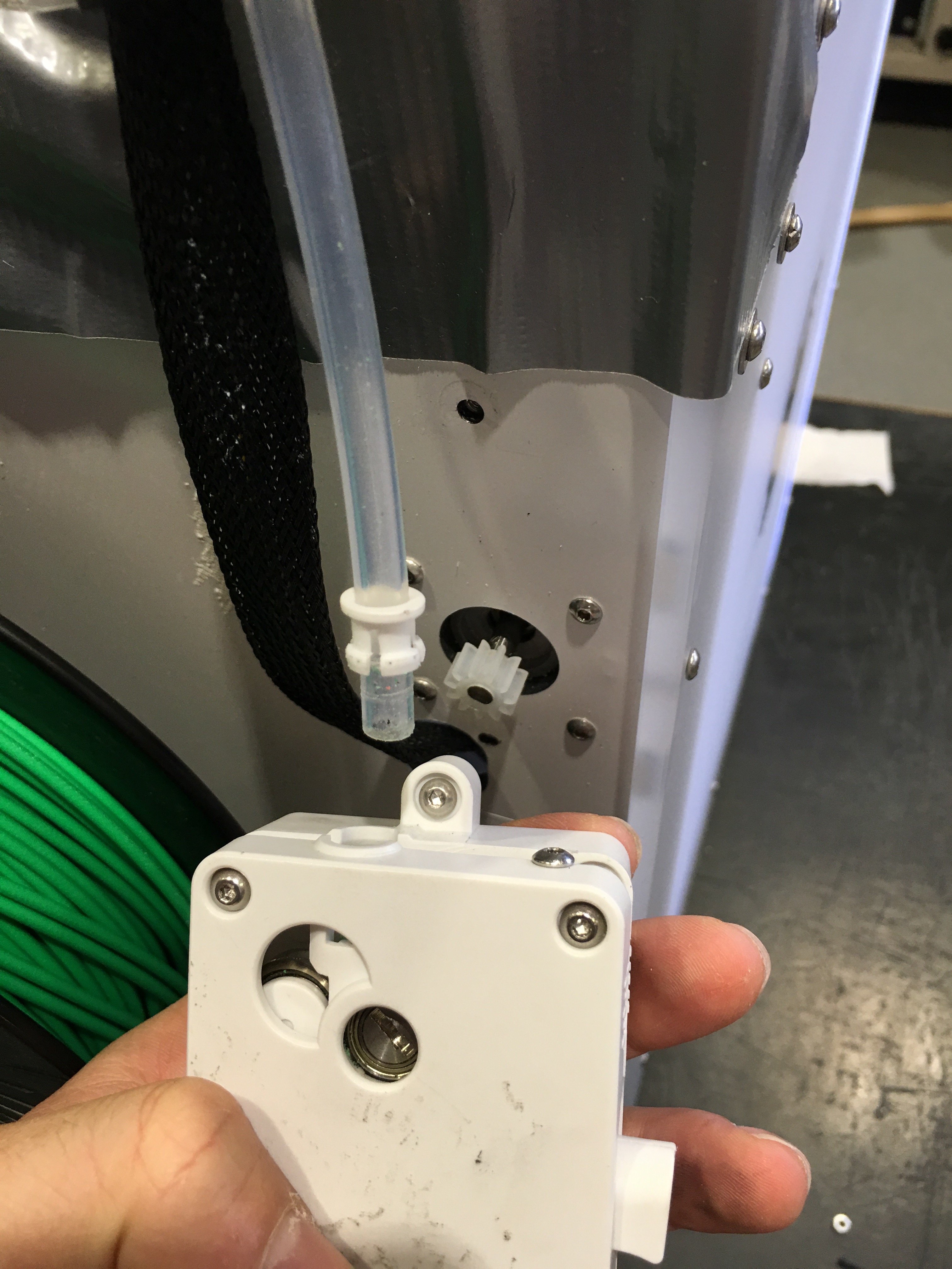
1) Use 2.5 mm hex key to take of feeder from Ultimaker
2) Open the case
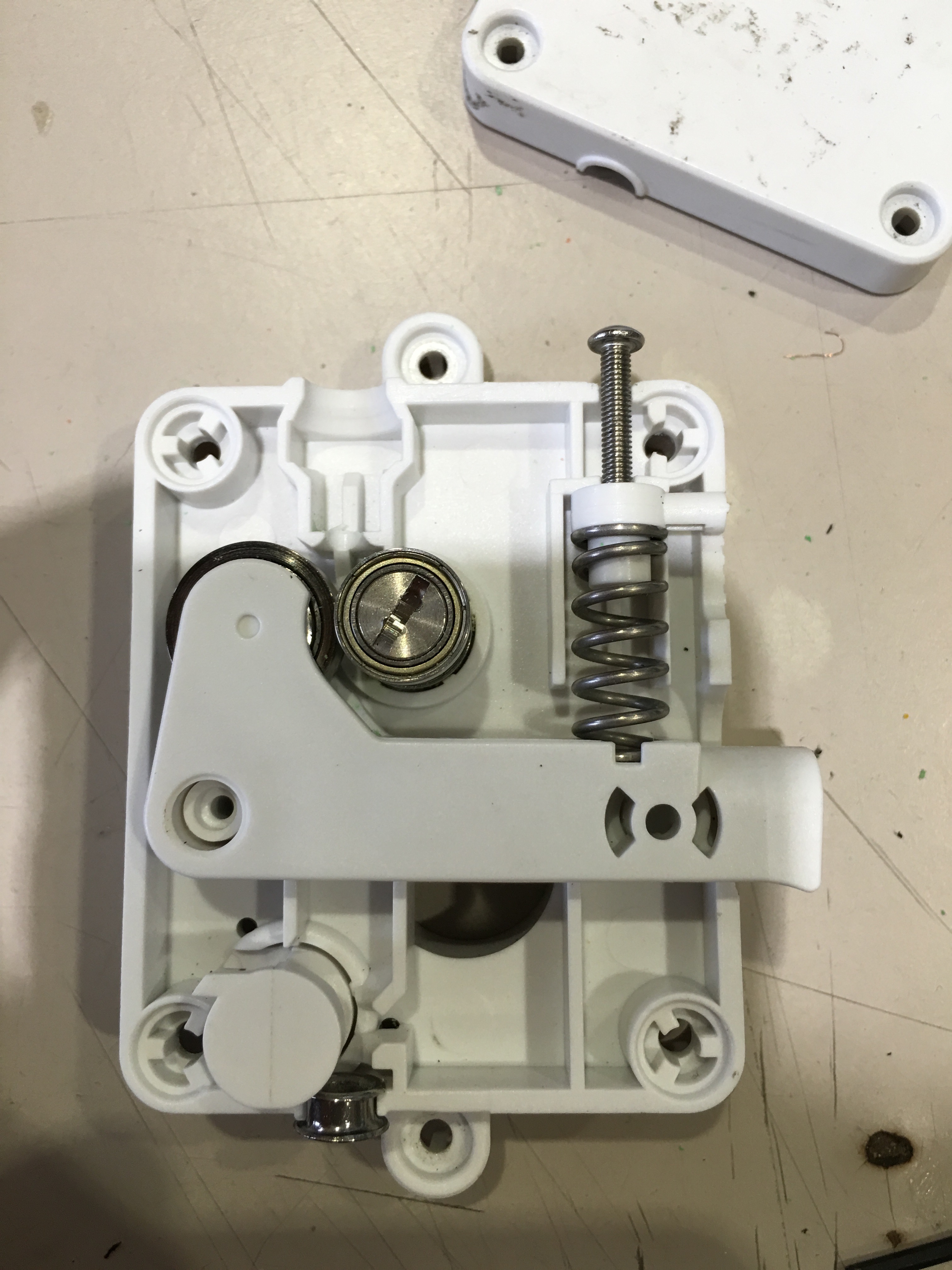
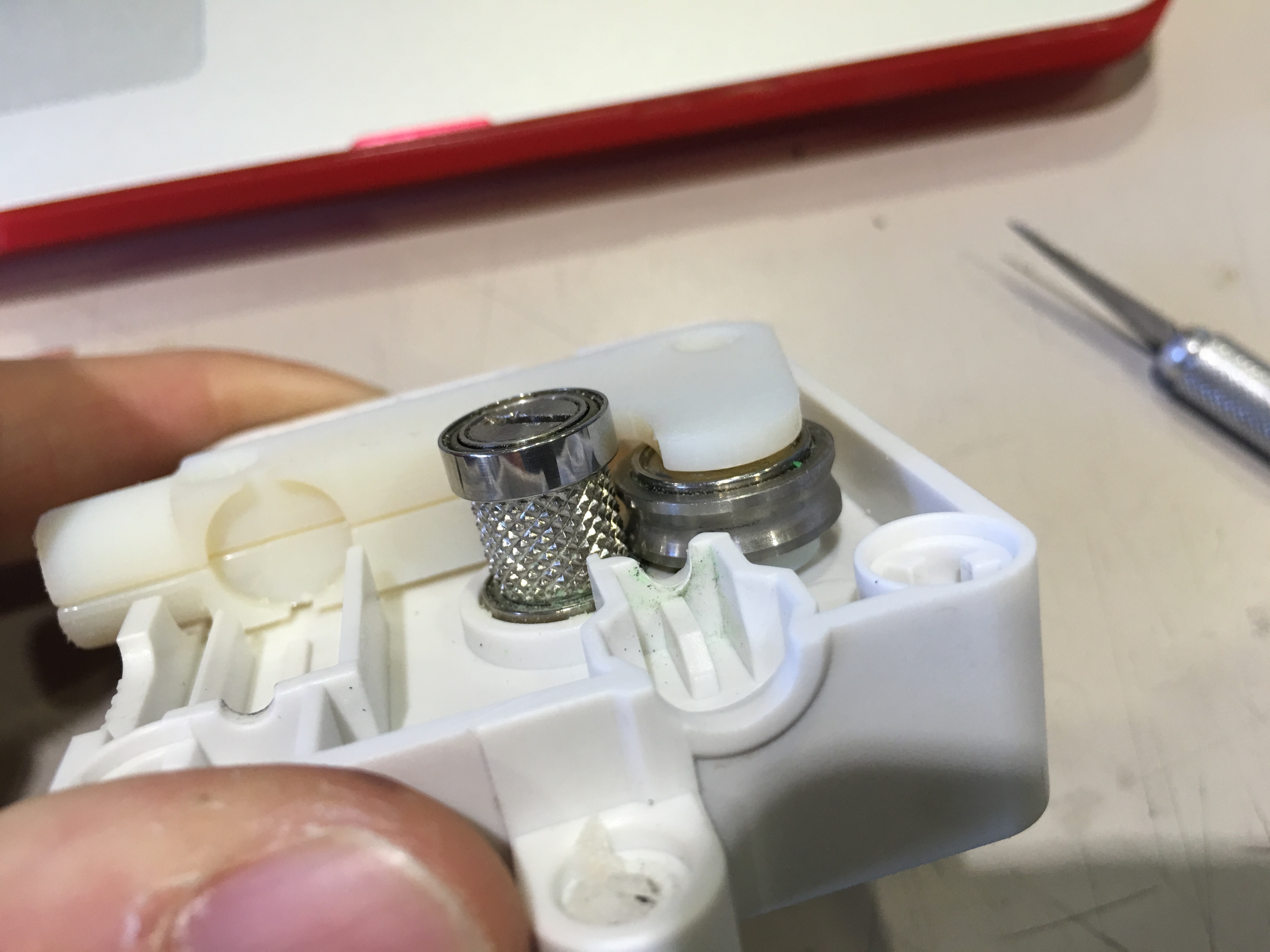
3) Dissemble arm, spring system, don't dissemble the gear and metal bearing.
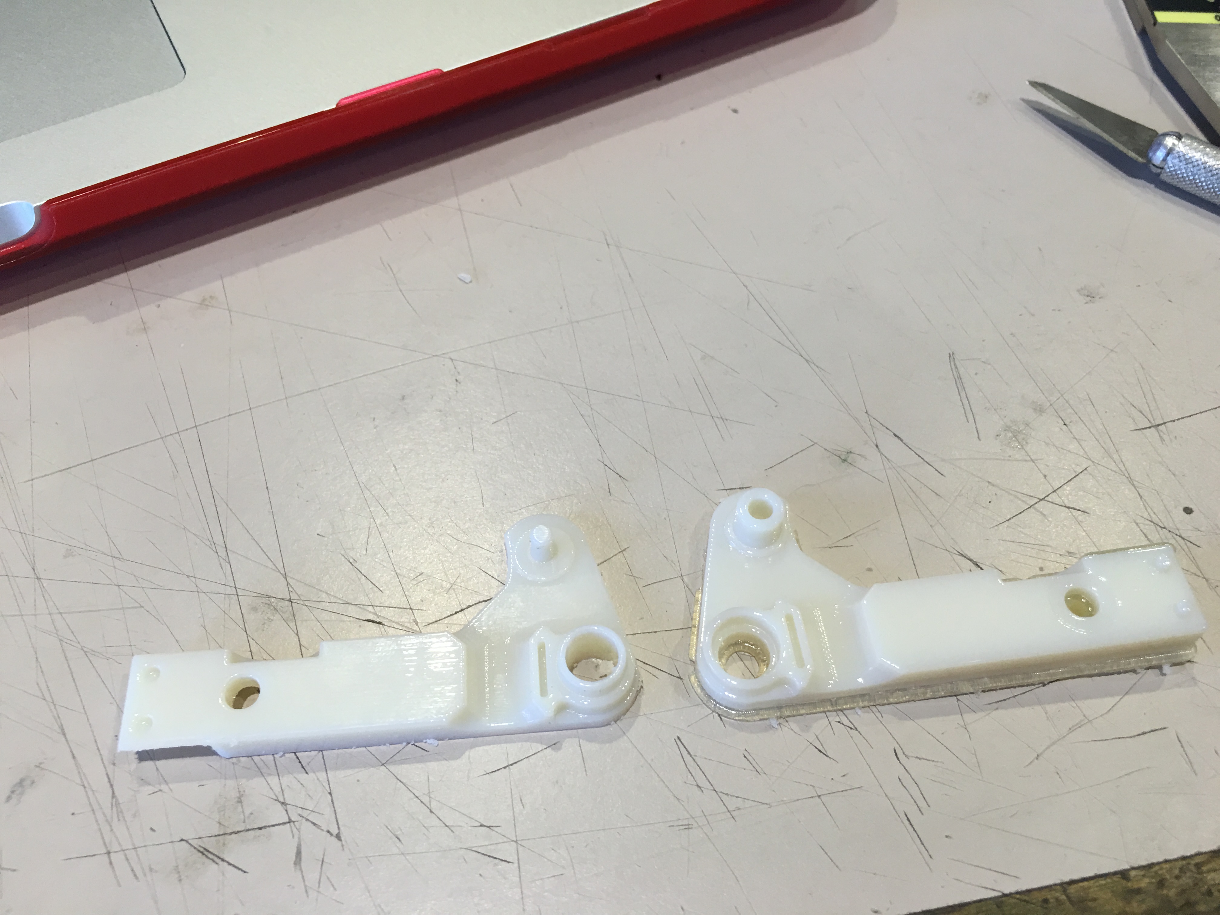
4) Dissemble arm into 3 pieces, be gentle, you don't want to break it because you will use same arm to feed 3mm filaments, my new development will not work for 3mm filaments, because the gap is going to be too tight.
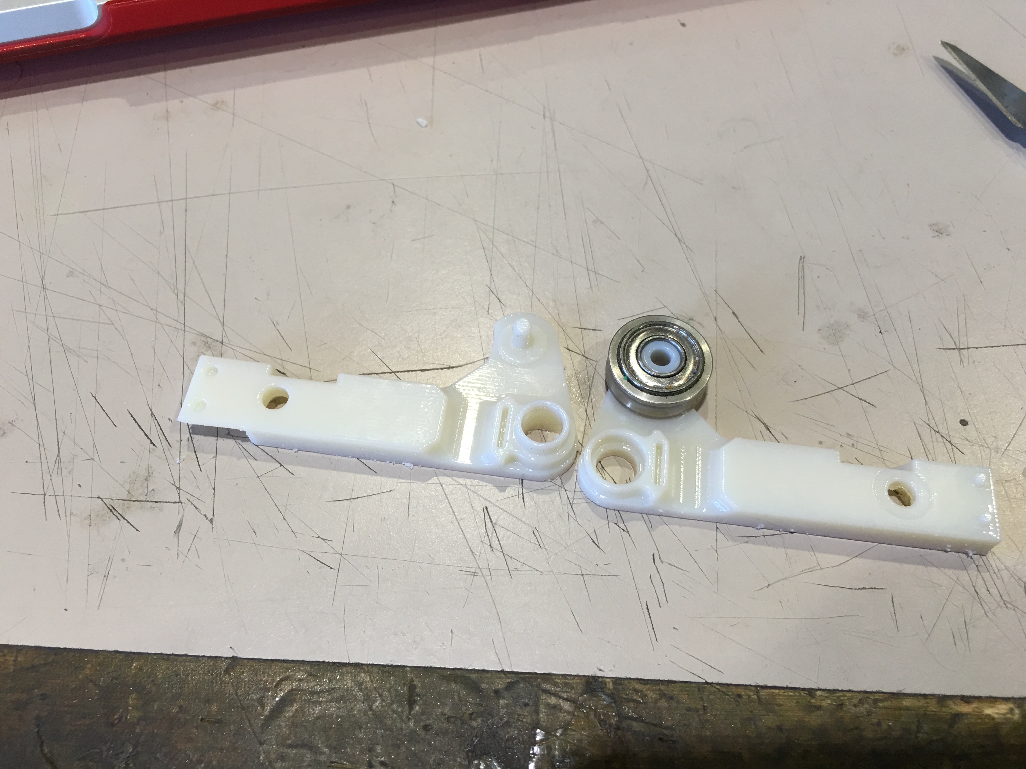
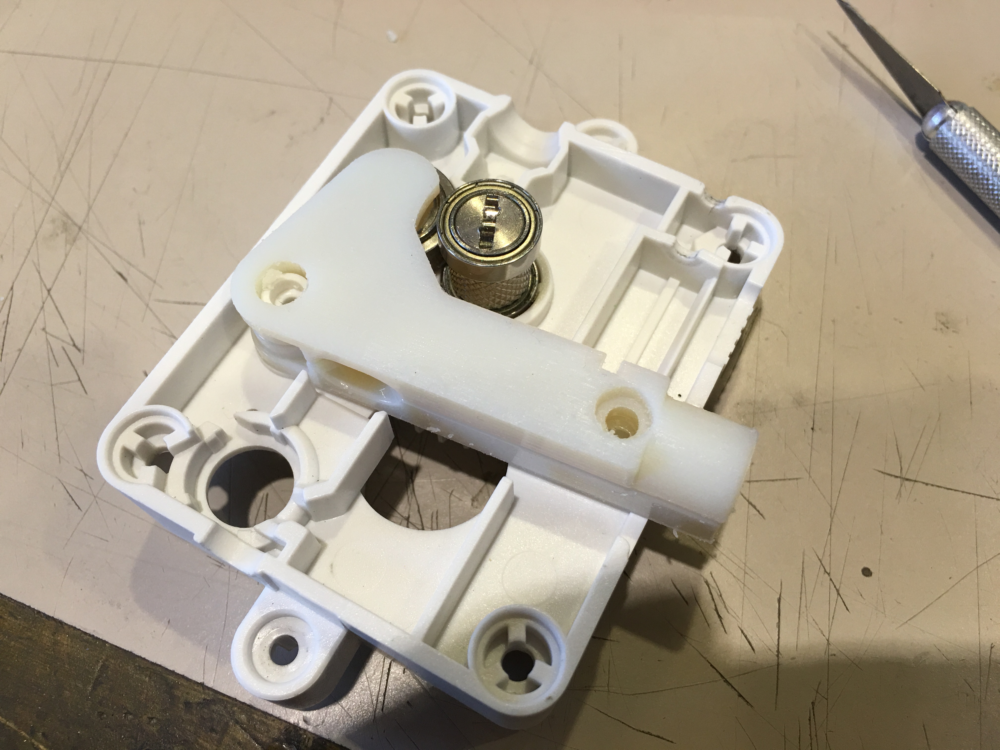
5) Assemble the metal roller into my 3D printed arm. (see the pictures)
6) Then Assemble the 3D printed arm with the roller into the case.
7) Check the gap by putting 1.75 mm filament (see the pictures)
8) Assemble spring and other parts as you see in the video
9) Close the cover and connect feeder mechanism to Ultimaker back.
Warning: Don't lose any parts that you dissemble, because you will NEED them back for printing 3mm filaments
Printing Settings for 1.76 Mm Conductive Filament on CURA and ULTIMAKER2 Types
Printing settings for 1.76 mm conductive filament on CURA and ULTIMAKER2 types,
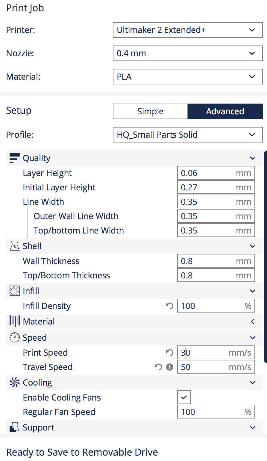
After you install developed arm design into the ultimaker, you should follow these settings for perfect printing with 1.75 mm filament. See the screenshot picture from the cura software. I print my perfect conductive lines with those settings. The REALLY REALLY IMPORTANT setting is the printing speed. You should print slow, because printing slow will help 1.75 mm filament to fill the nozzle after it melts, and stabilize the printing pressure. 20 mm/s is great. Check my settings.
After that go to Ultimaker and make the following settings on the machine:
Settings for Ultimaker:
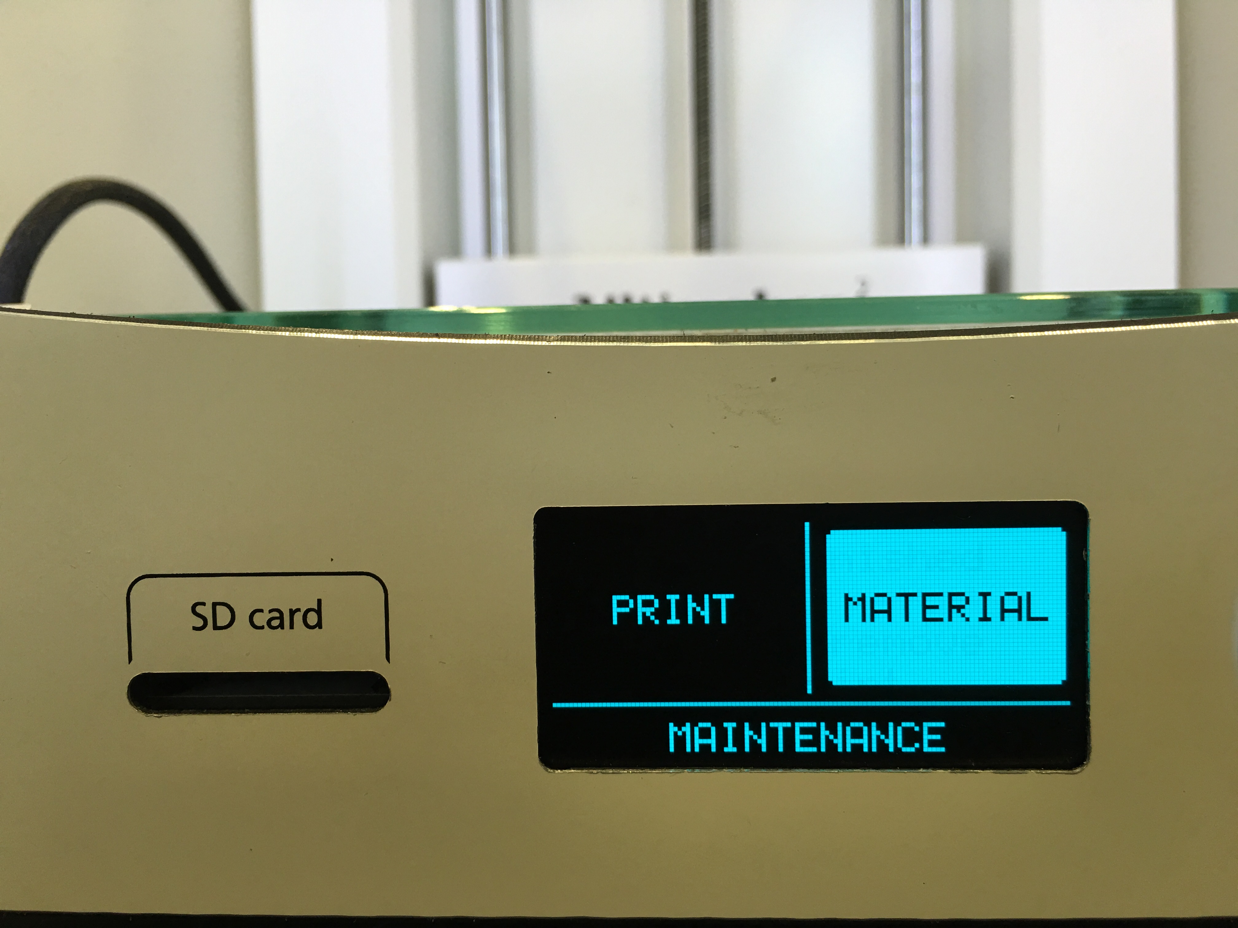
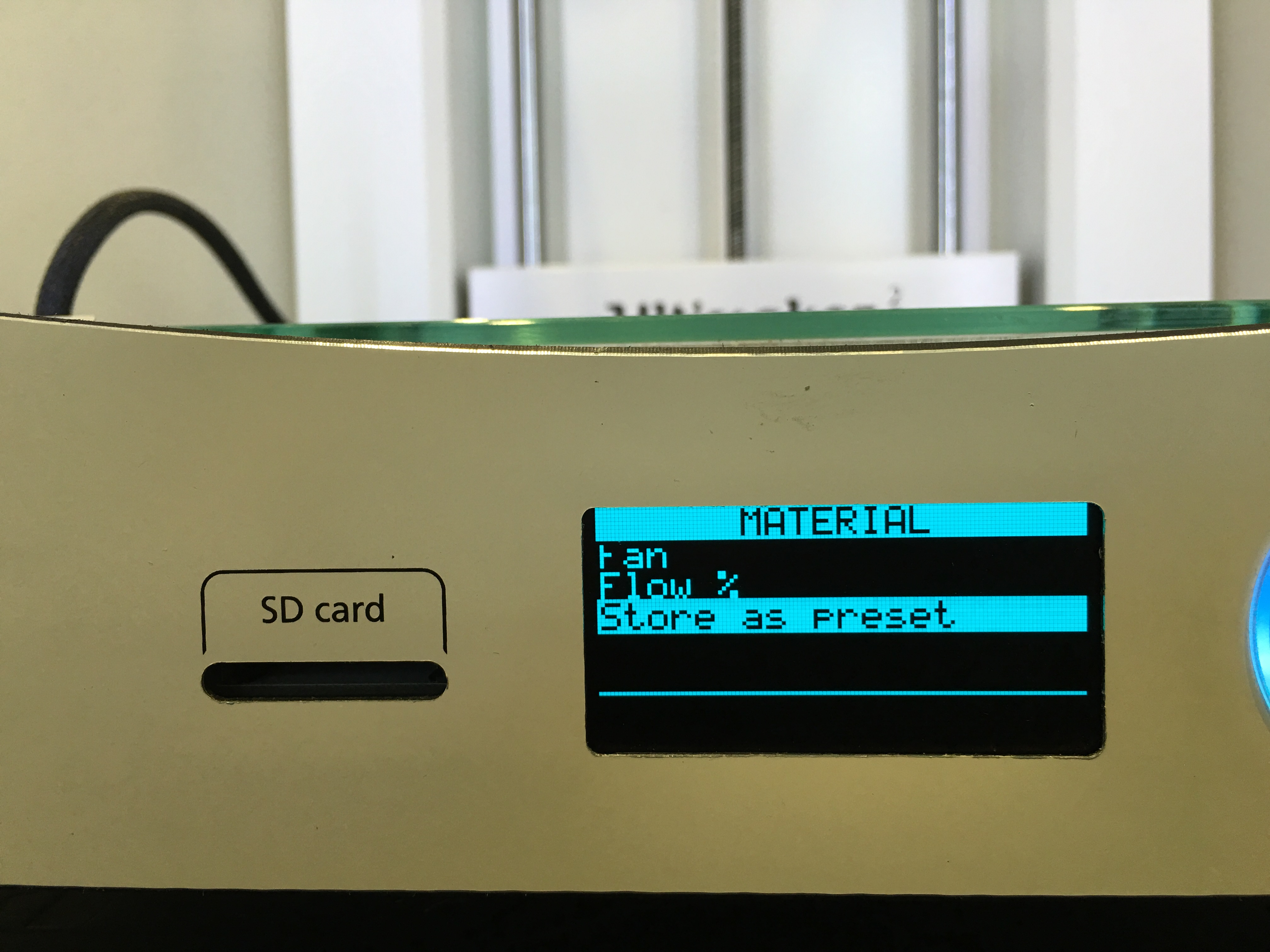
1) Go to Material
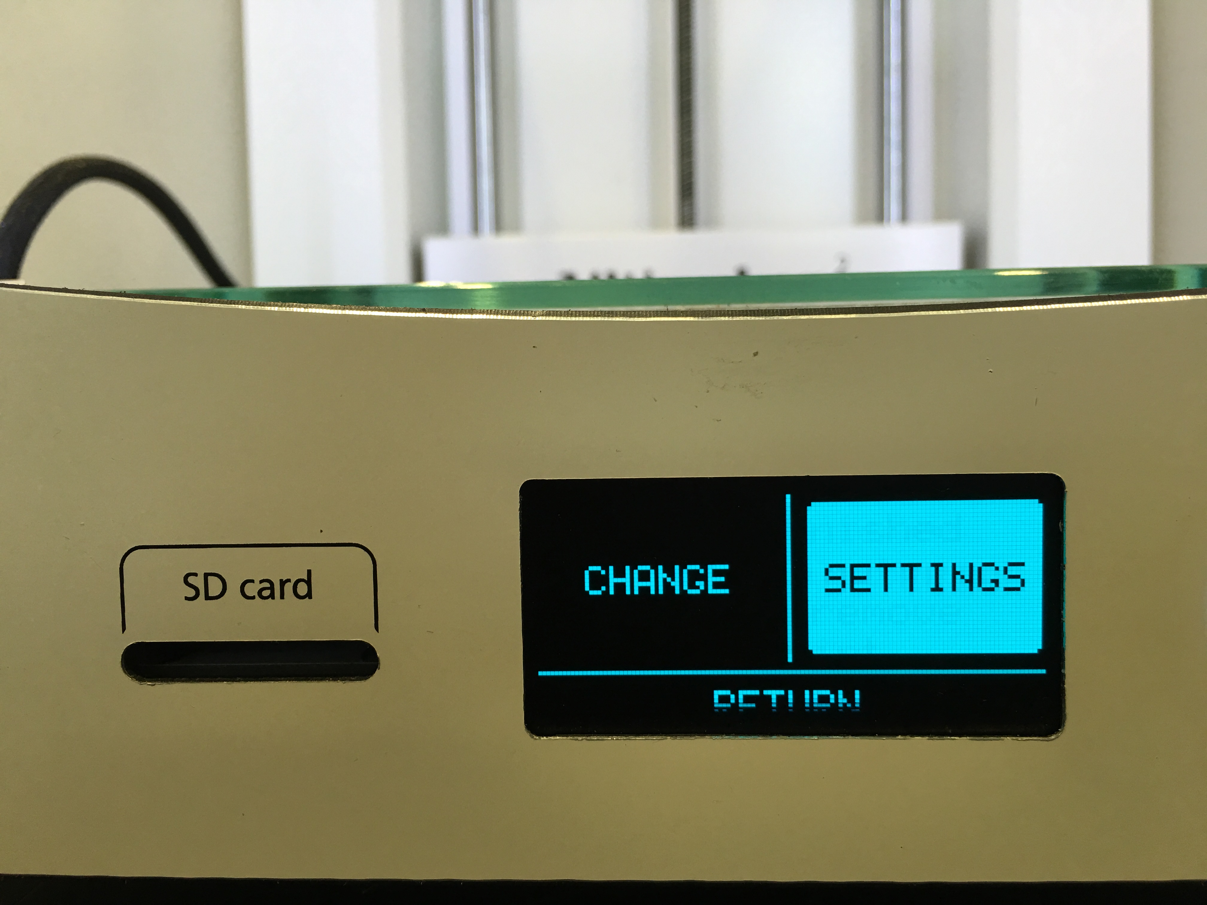
2) Go to Settings
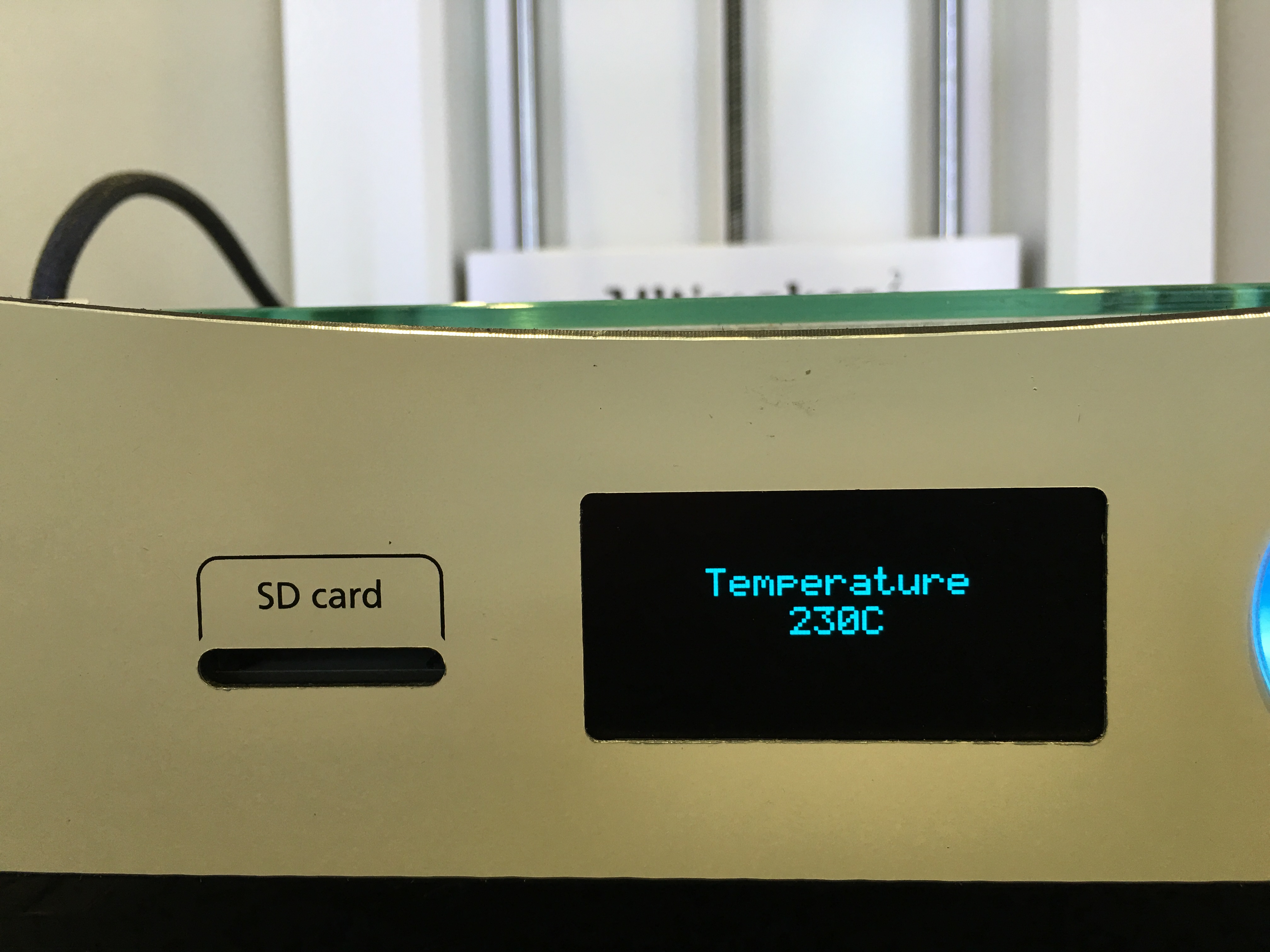
3) Go to Temperature
4) Change temperature 1 into 230 (it might be different for other 1.75 mm conductive PLA, be sure by looking your filament providers website)
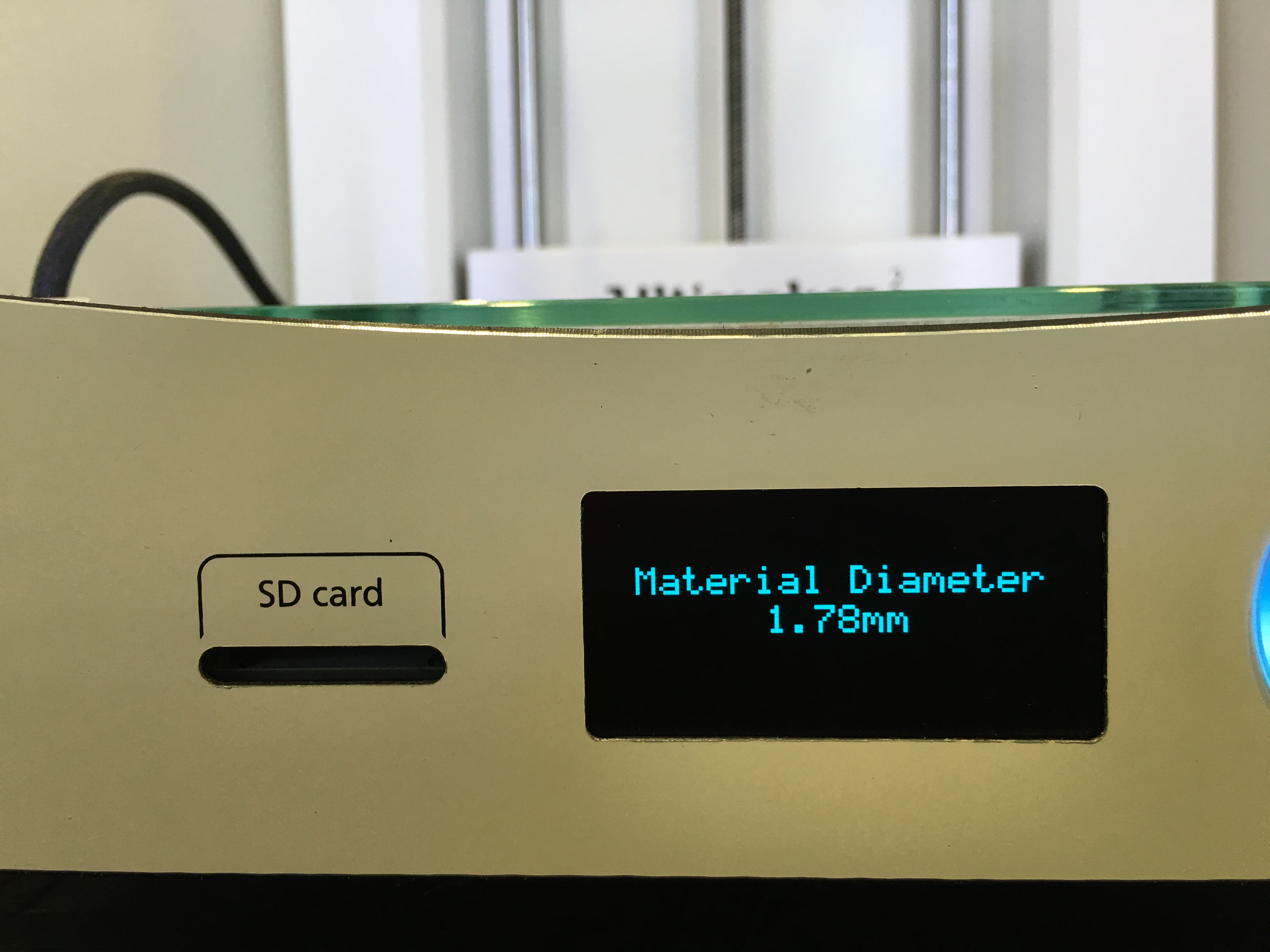
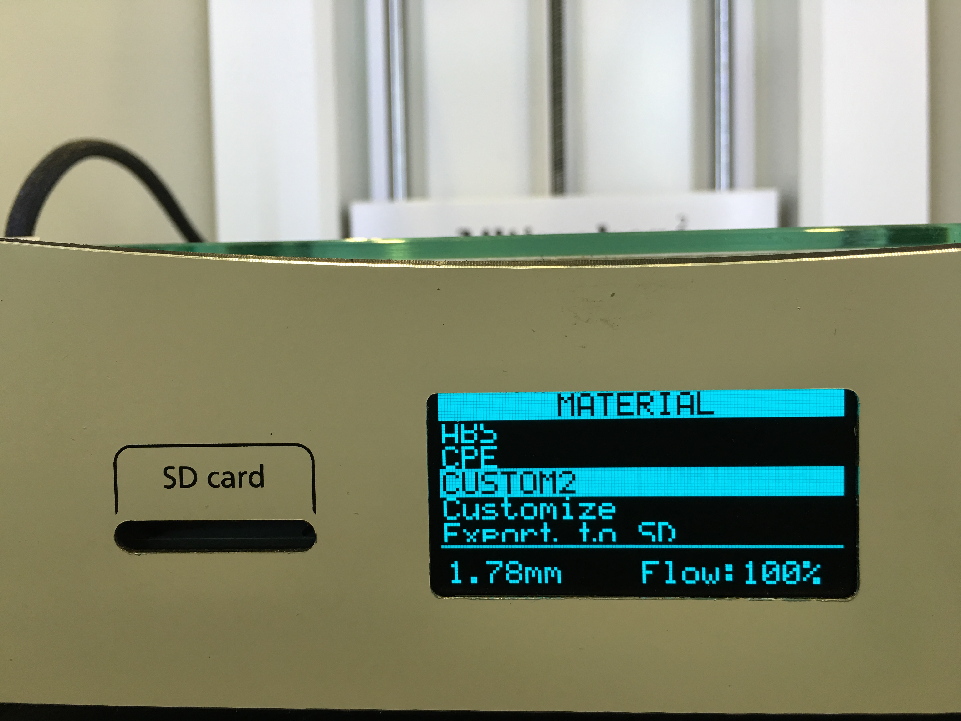
5) then go to filament diameter and make it 1.78mm (little higher than what you have)
6) Then click store as present
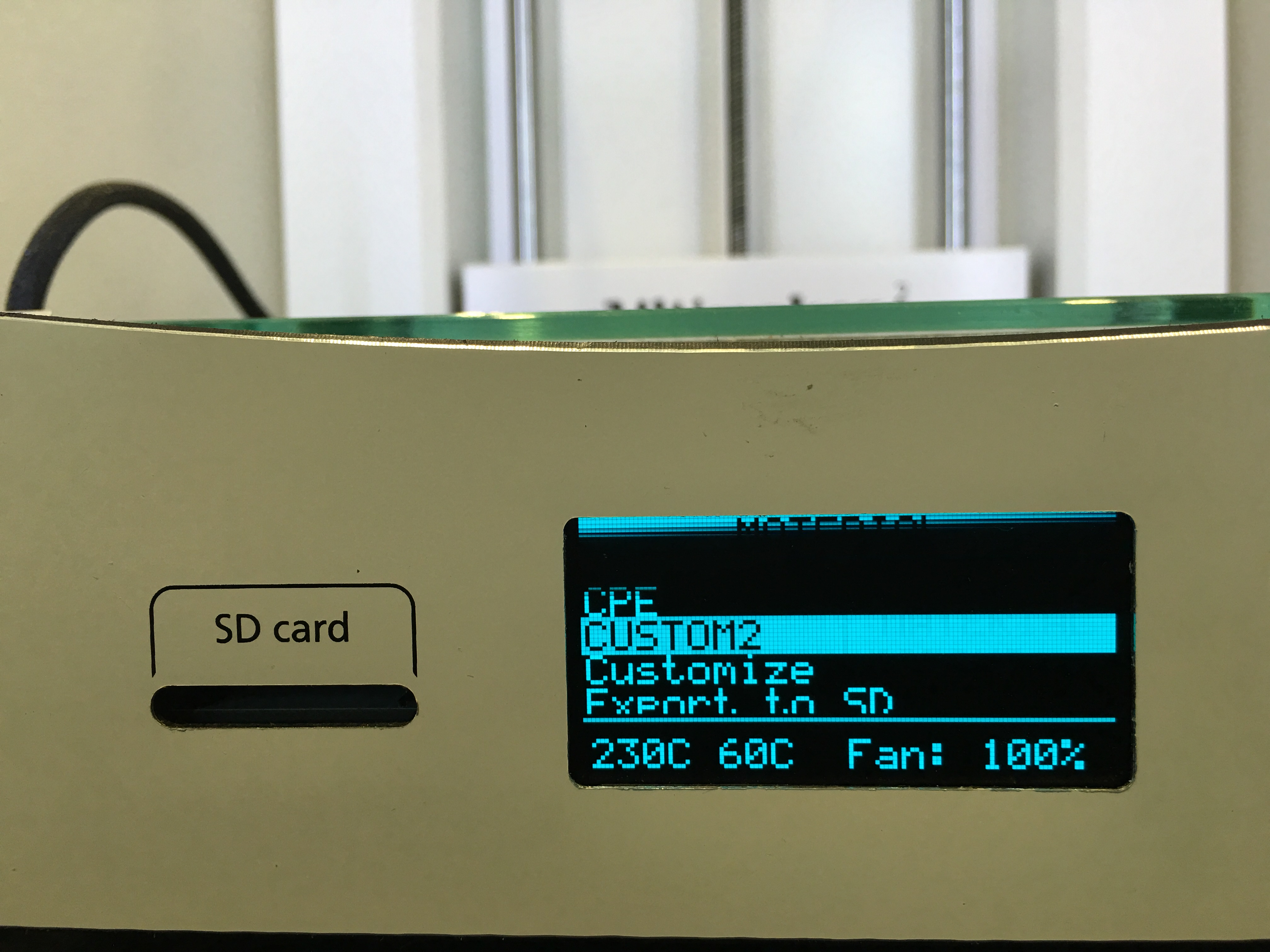
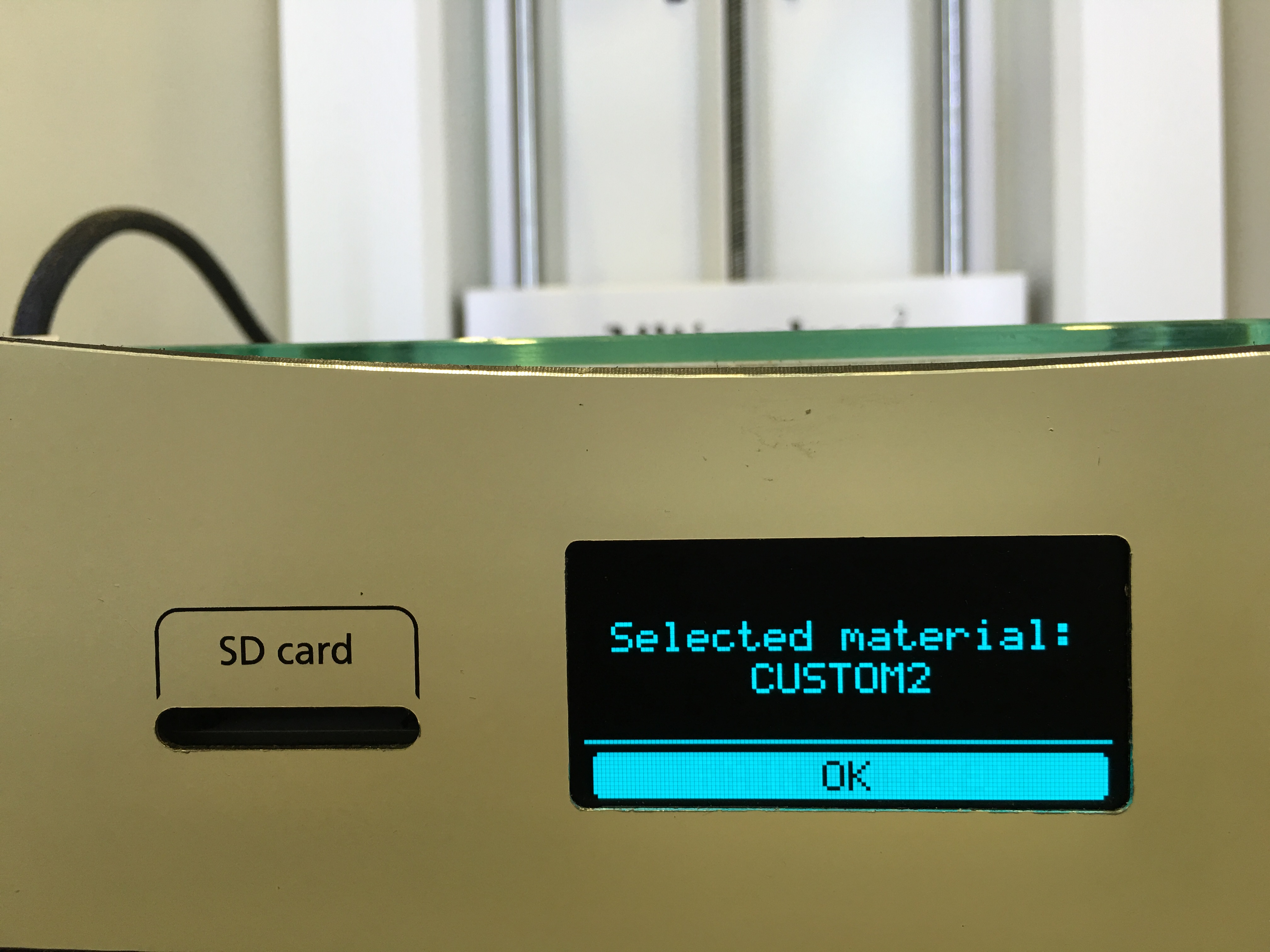
7) Then Select your material for printing. Its name should be CUSTOM or CUSTOM2 depending on your previous saves.
8) See your selected material as CUSTOM2
NOW you are ready to print. :)
3D Printing the First Conductive Circuit and Moving to Big Projects (BONUS)
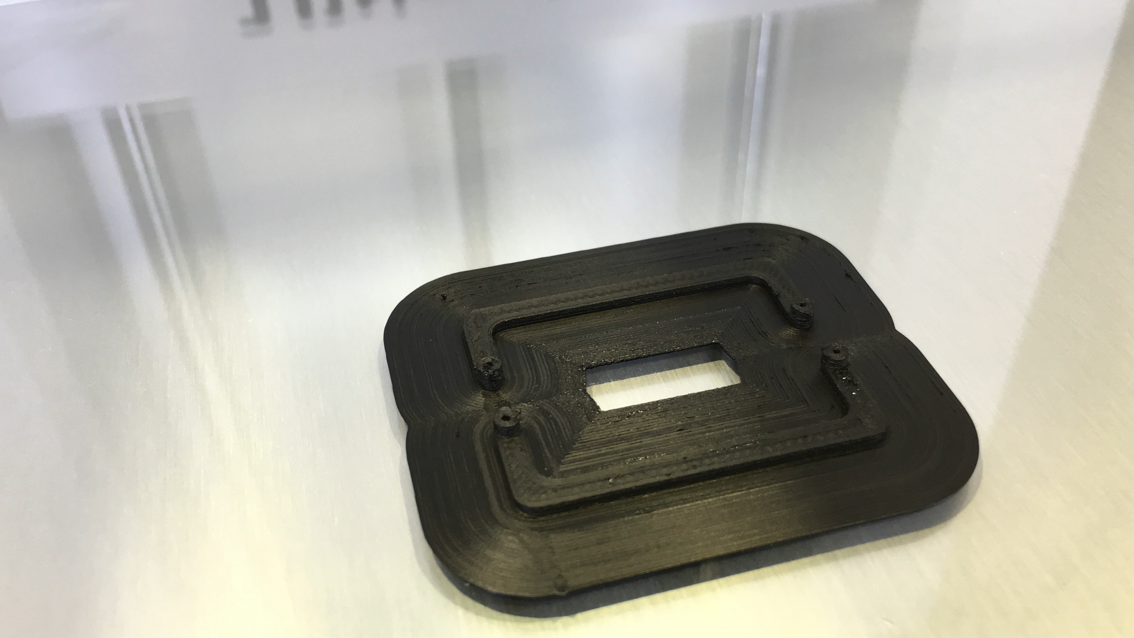
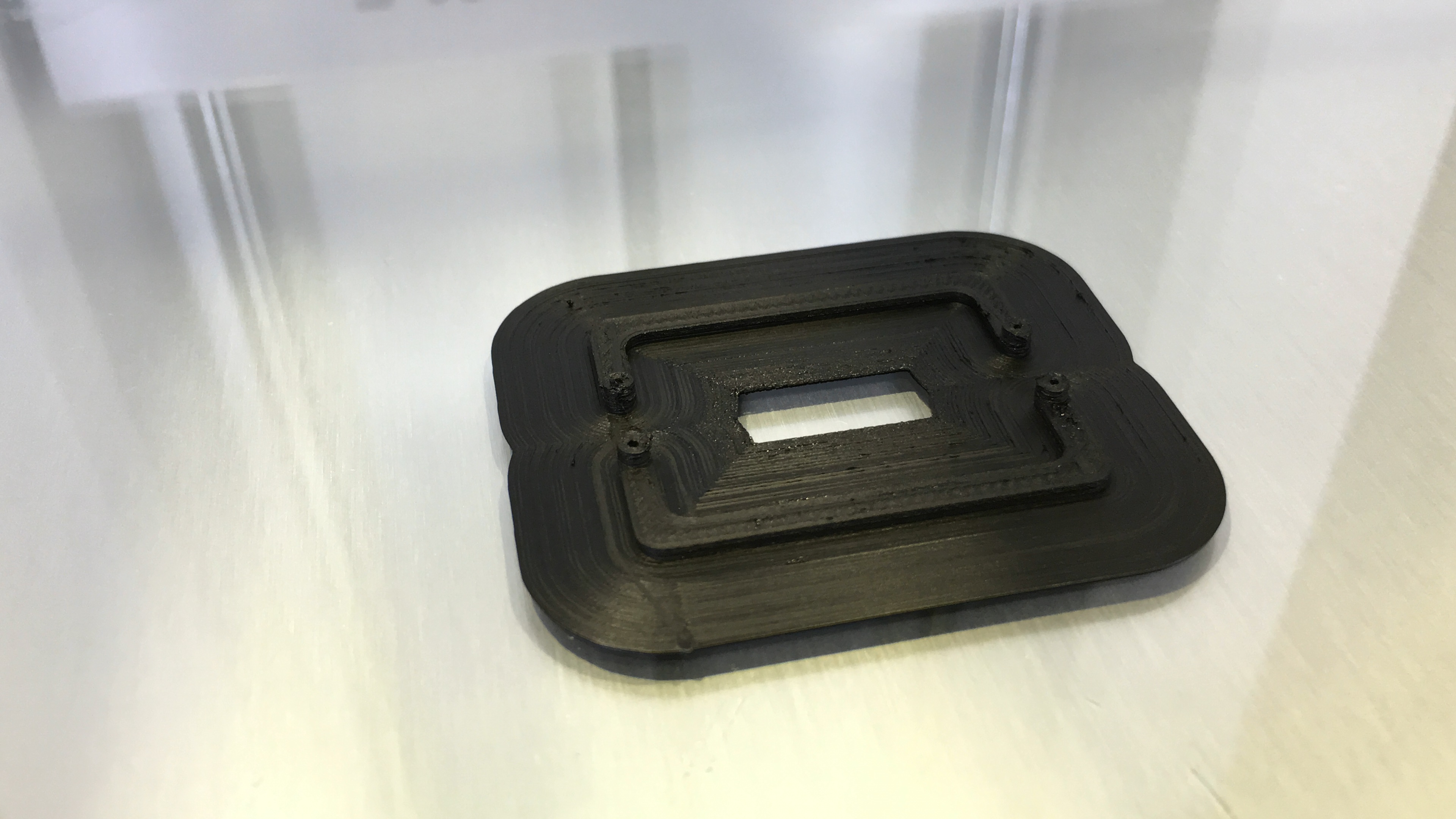
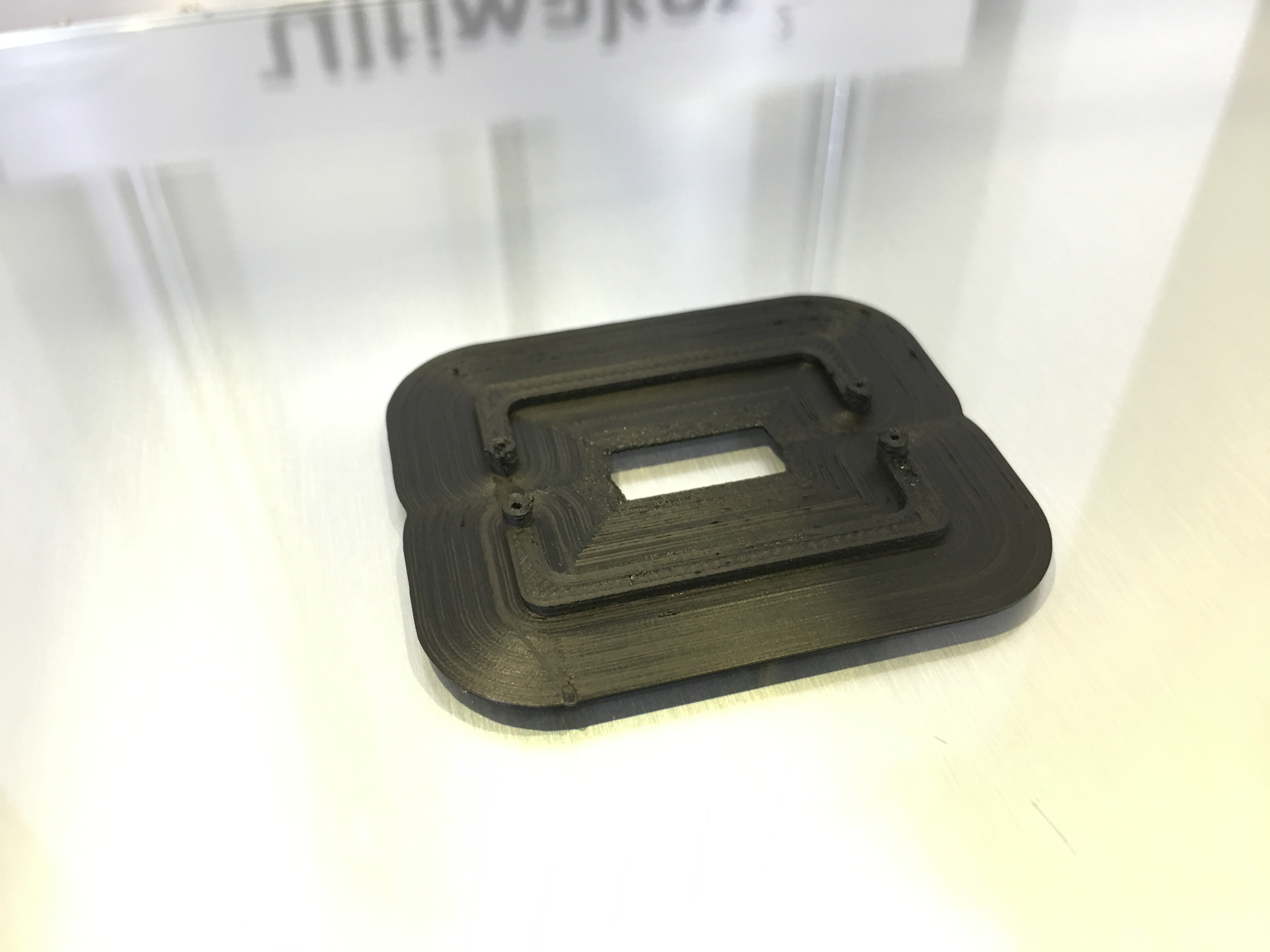
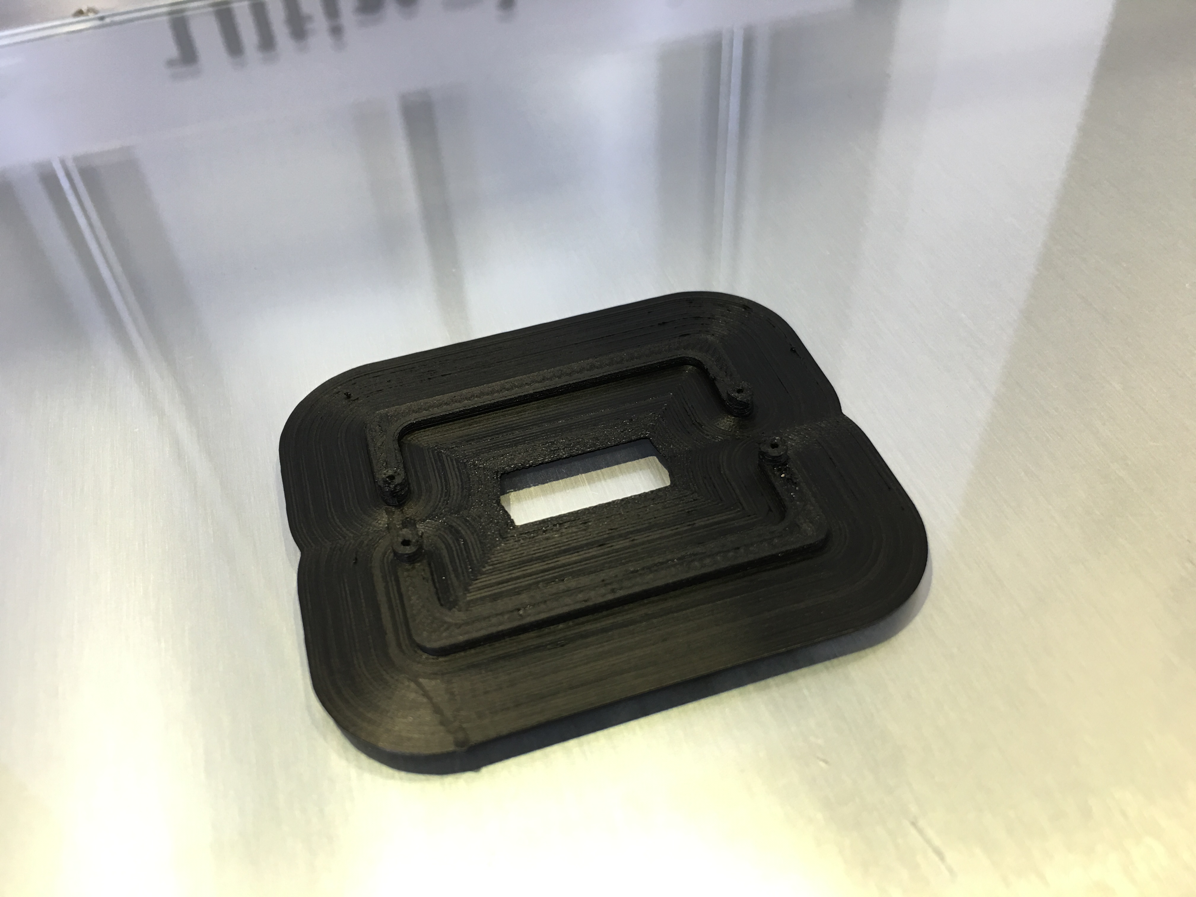
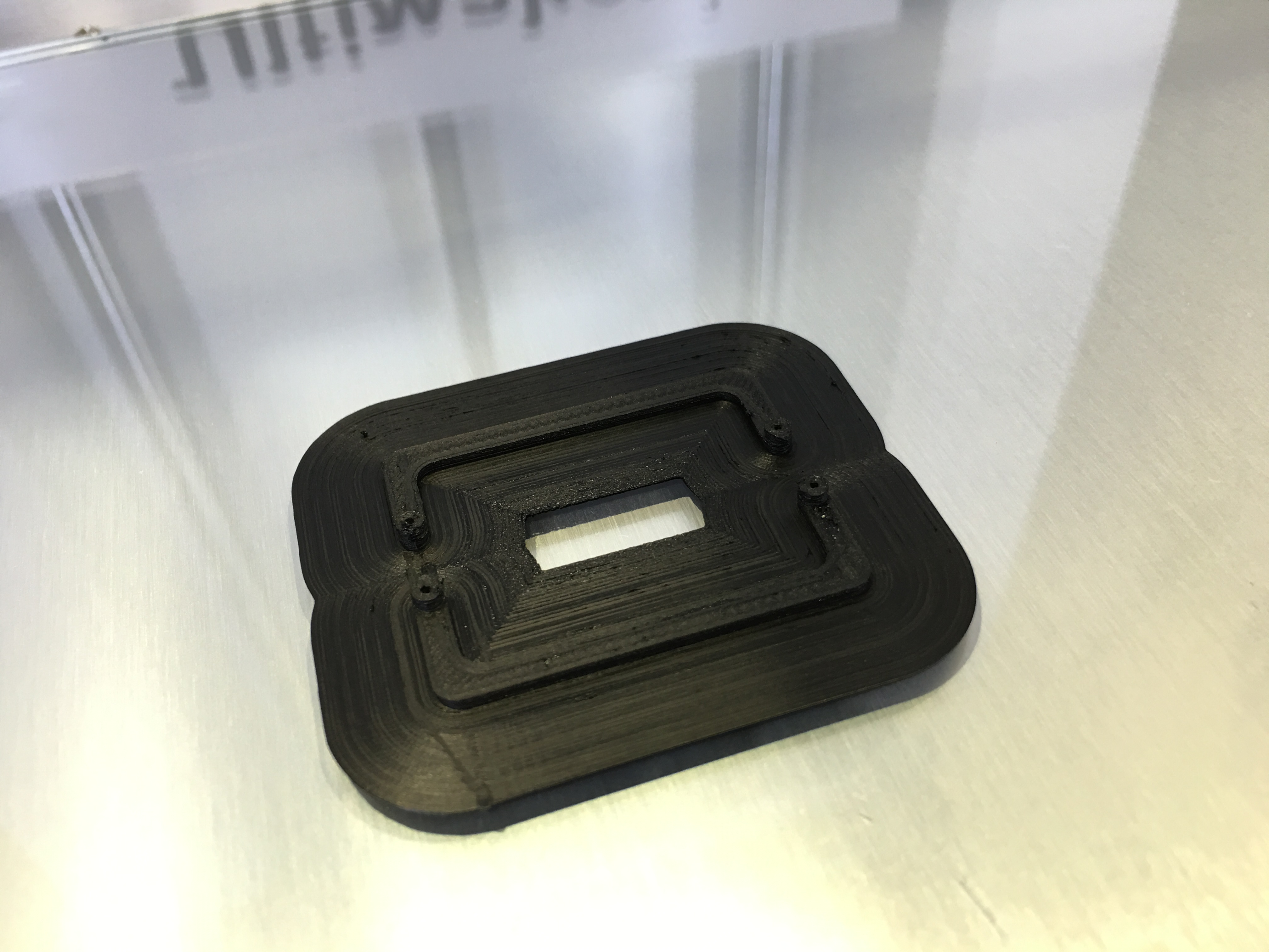
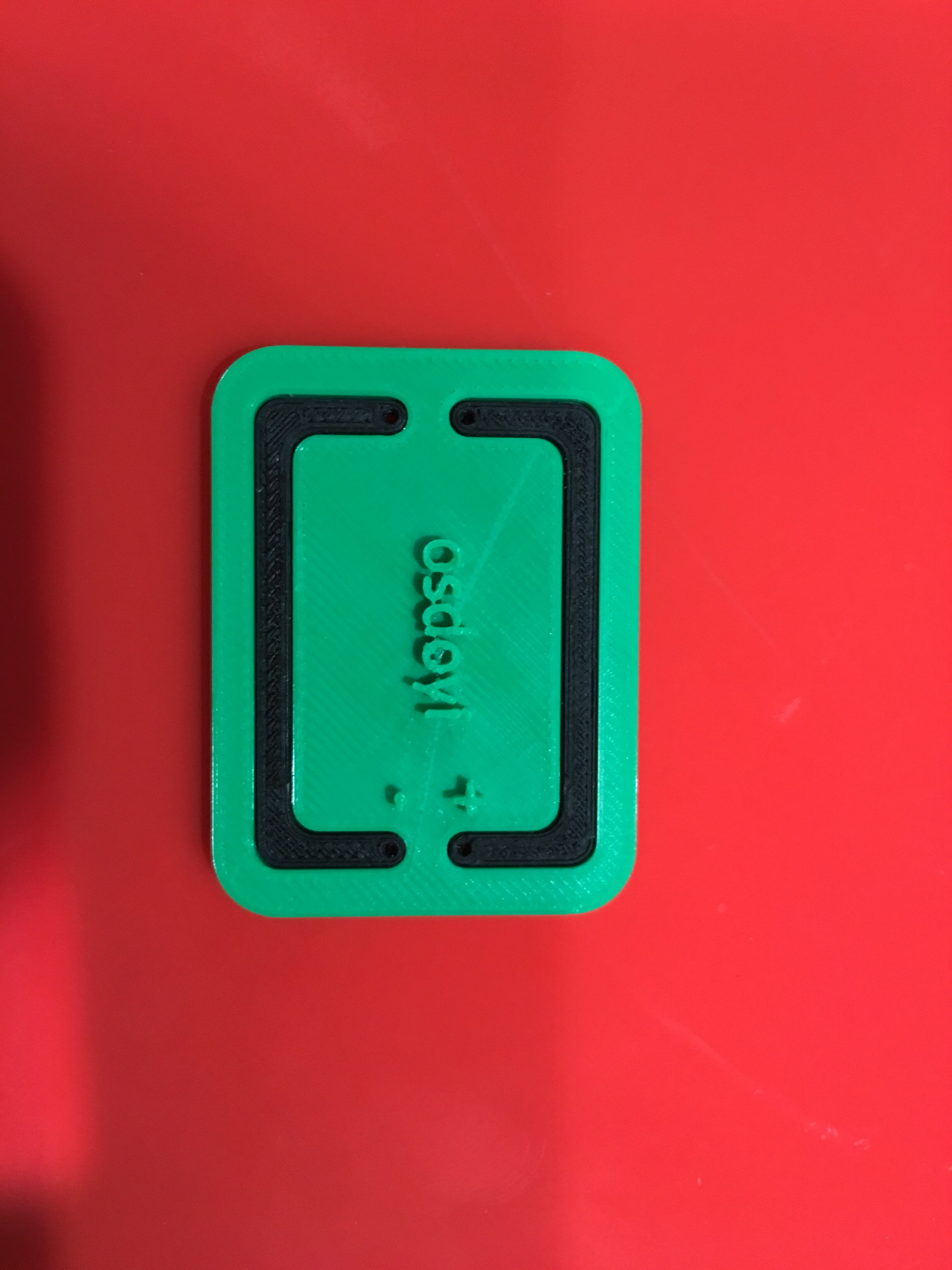
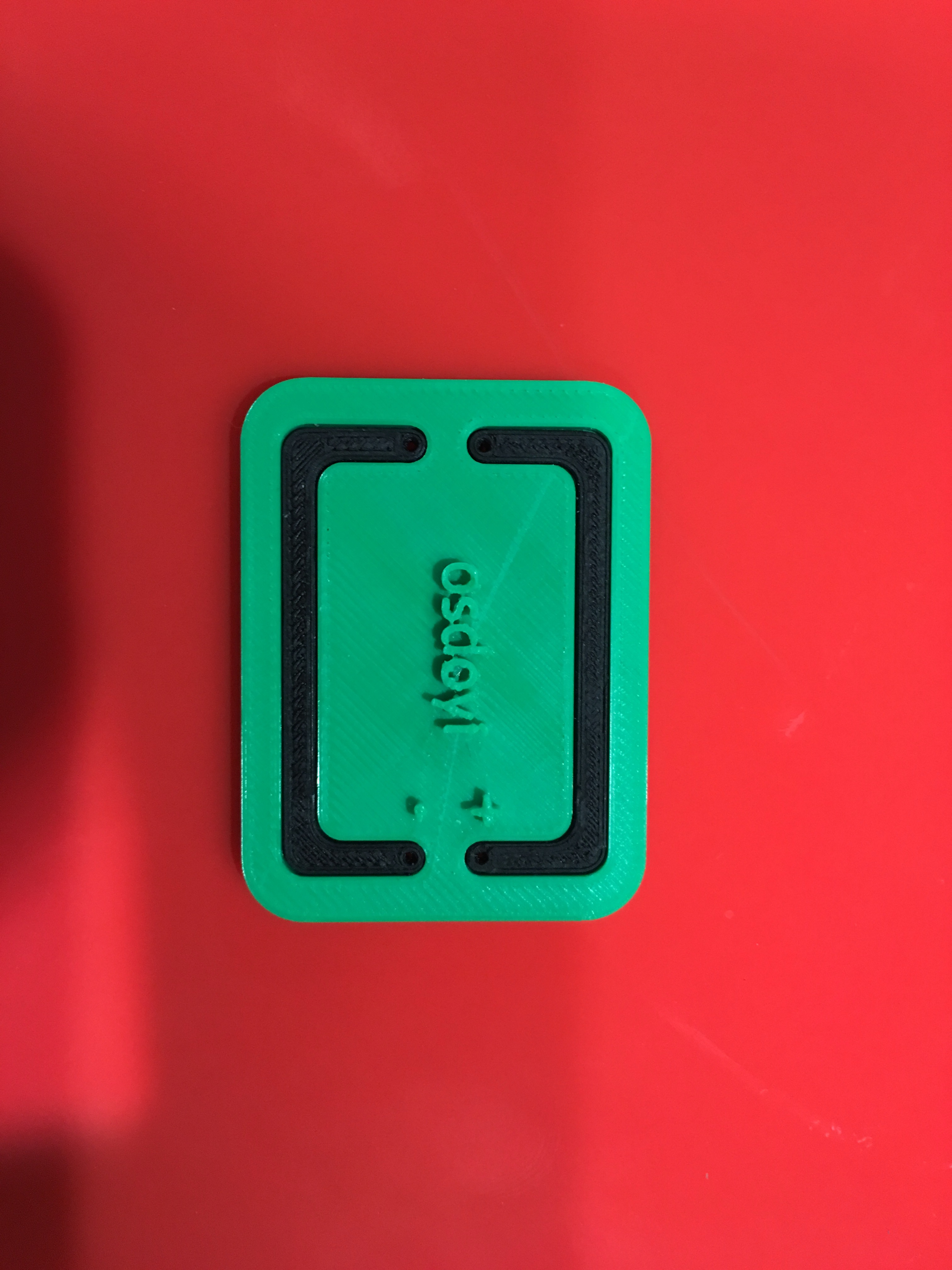
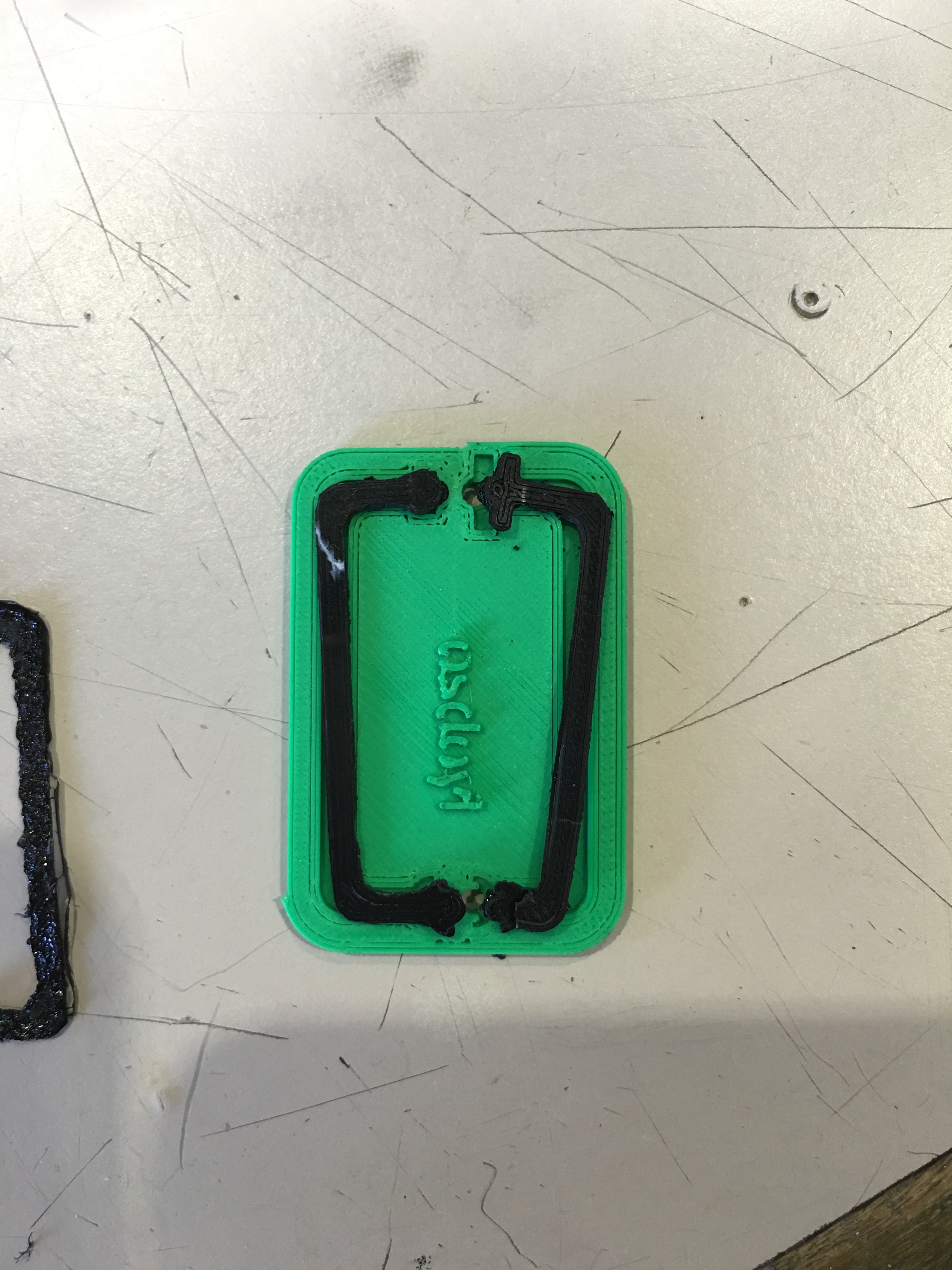
Now it is time to print for us. Here is my files lines3.stl and circuit3.stl
Print lines3.stl with the new settings for 1.75 mm diameter conductive PLA, it will took no more than 30 minutes. and then print circuit3.stl with normal 3mm diameter PLA with current Ultimaker arm not with developed arm.
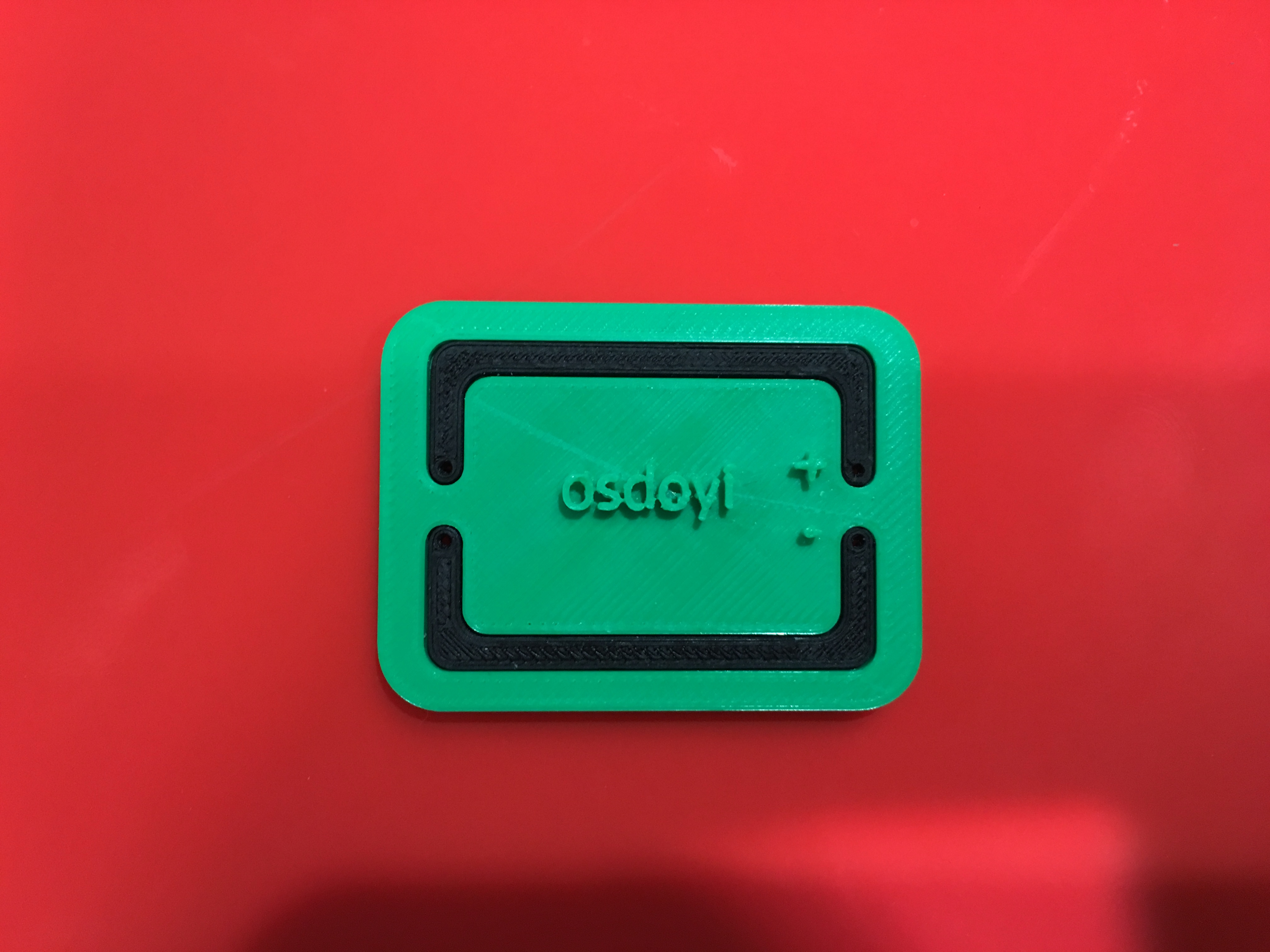
Then assemble them together. Here is your FIRST CONDUCTIVE CIRCUIT. Congratulations !!!!!!!
Let's look at other possible circuits.
Other Circuit Options
Other Circuit Options,
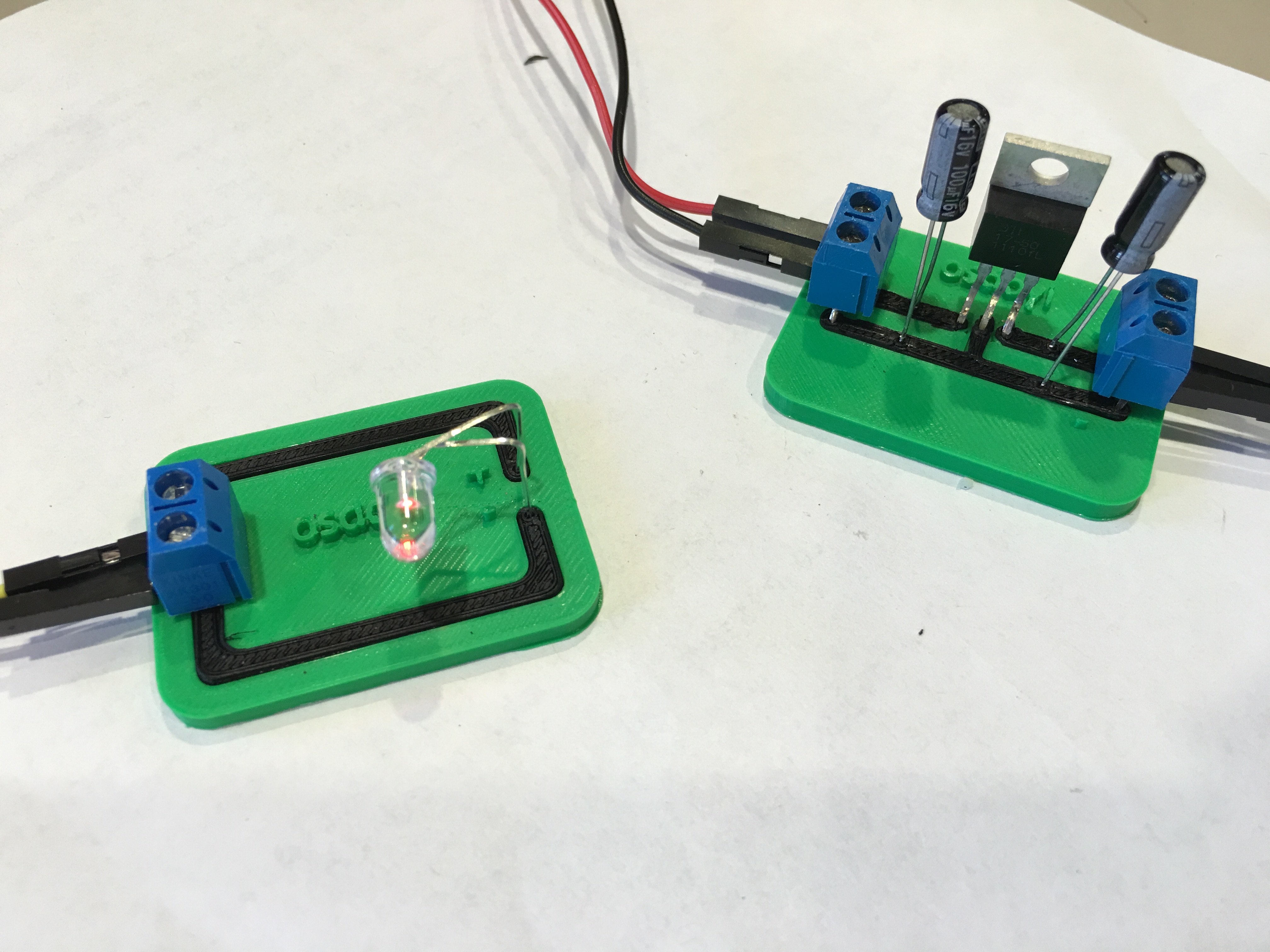
With the knowledge of conductive 3D printing you can build many circuits like voltage regulator. See the picture of my new circuit designs. I will explain them in more detail on my next instructables!
Have fun!