16-bit I2C Temperature Monitor Using Arduino
by Mendelbrot in Circuits > Microcontrollers
33240 Views, 35 Favorites, 0 Comments
16-bit I2C Temperature Monitor Using Arduino
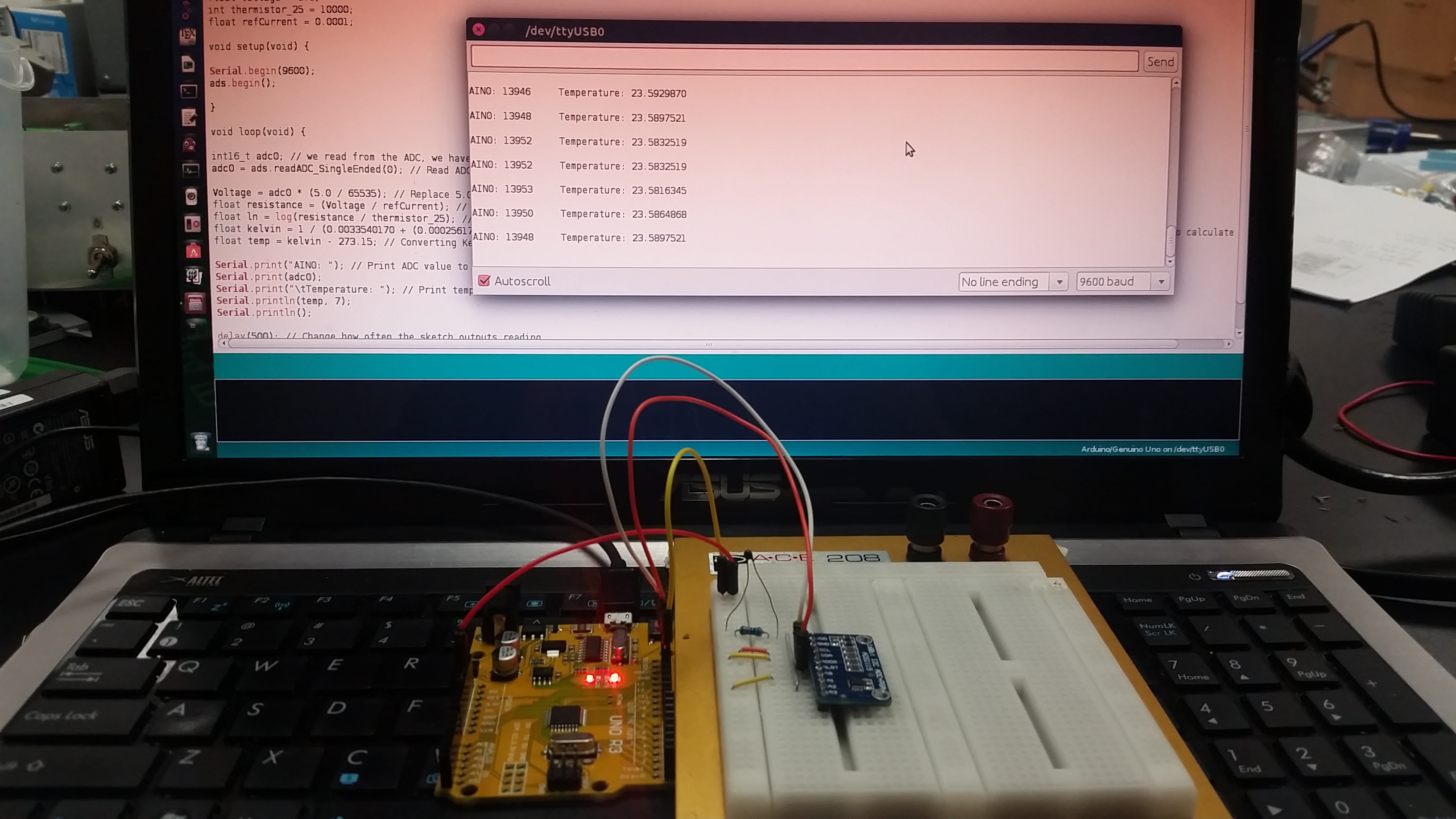
If you find yourself needing an ADC with greater resolution than the Arduino's onboard 10-bit ADC provides, the ADS1115 16-bit ADC is a popular and simple to use chip who communicates via I2C interface. Here, I will walk you through the steps of assembling your set-up, provide some code and go through a little theory. Let's get started!
Gather the Hardware
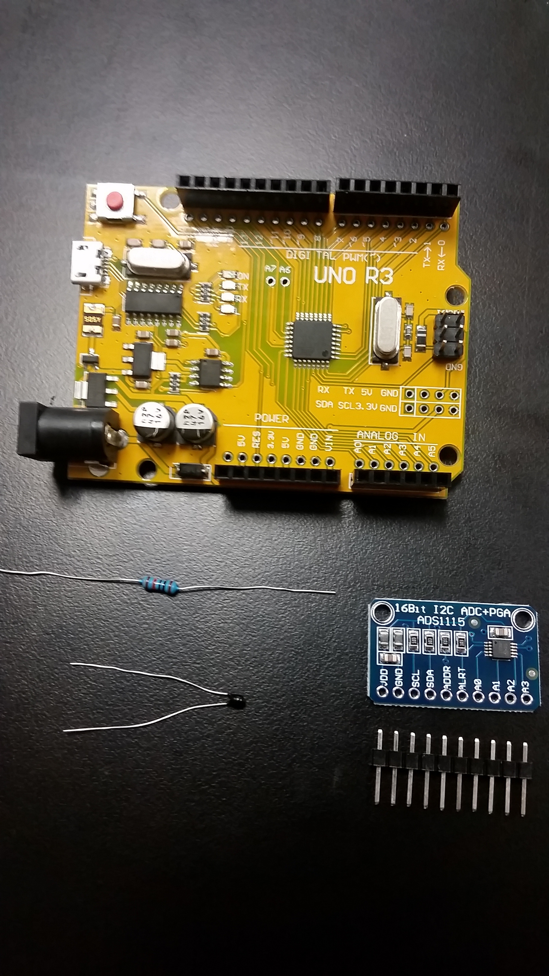
These are the ingredients you will need to get started:
- Arduino Uno
- Solderless Breadboard
- 16-bit I2C ADC (ADS1115)
- 10k Ohm resistor
- 10k Ohm NTC Thermistor
- Jumper Wires
Note: The ADS1115 can be found on Amazon and eBay for a wide range of prices. I ordered 5 off of eBay from China for less than the price of one on Amazon and they arrived in about 2 weeks. Definitely do your homework to find a balance between project lead-time and price willing to pay. As far as I can tell the boards are identical.
ADS1115 16-bit ADC+PGA
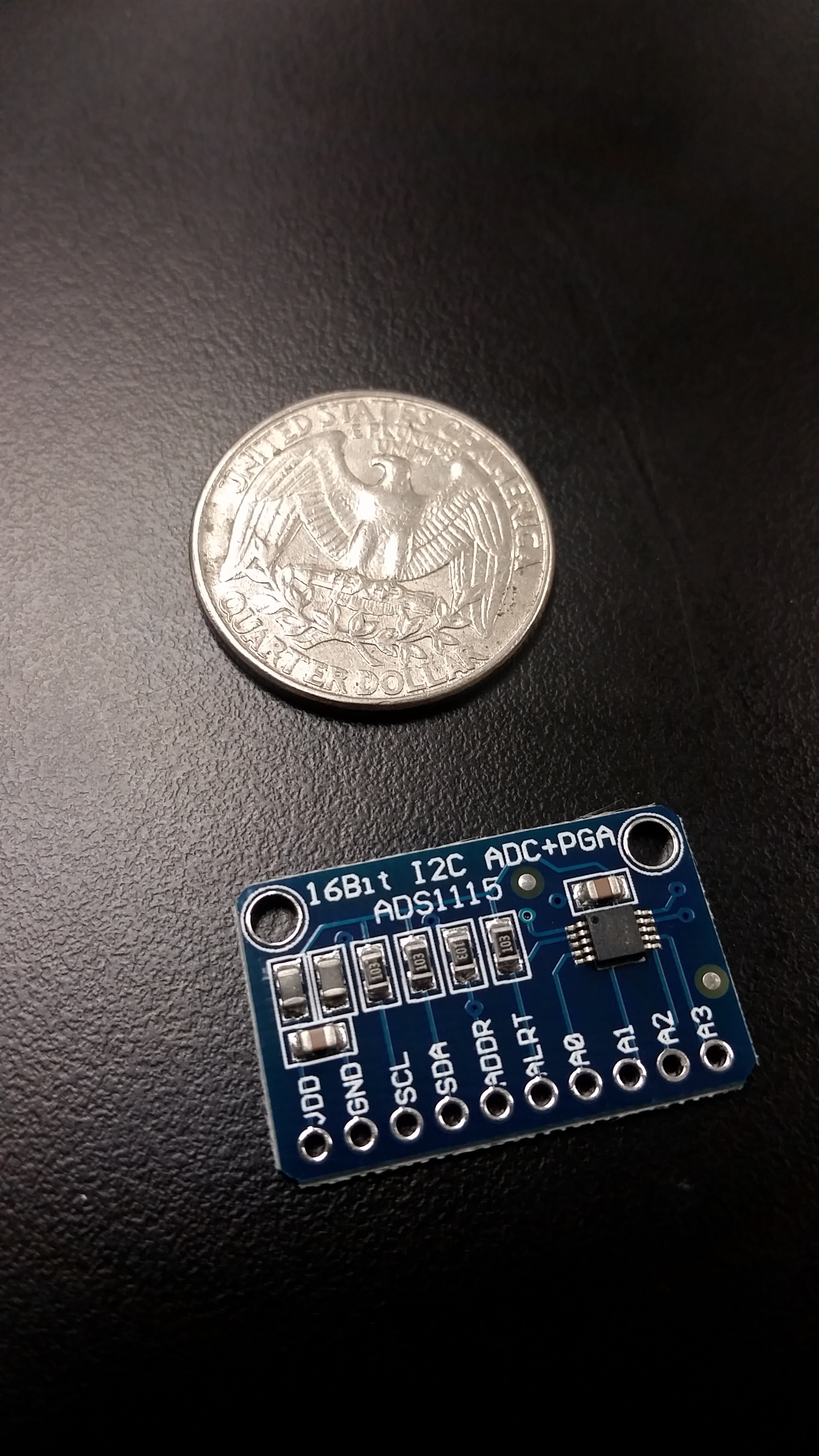
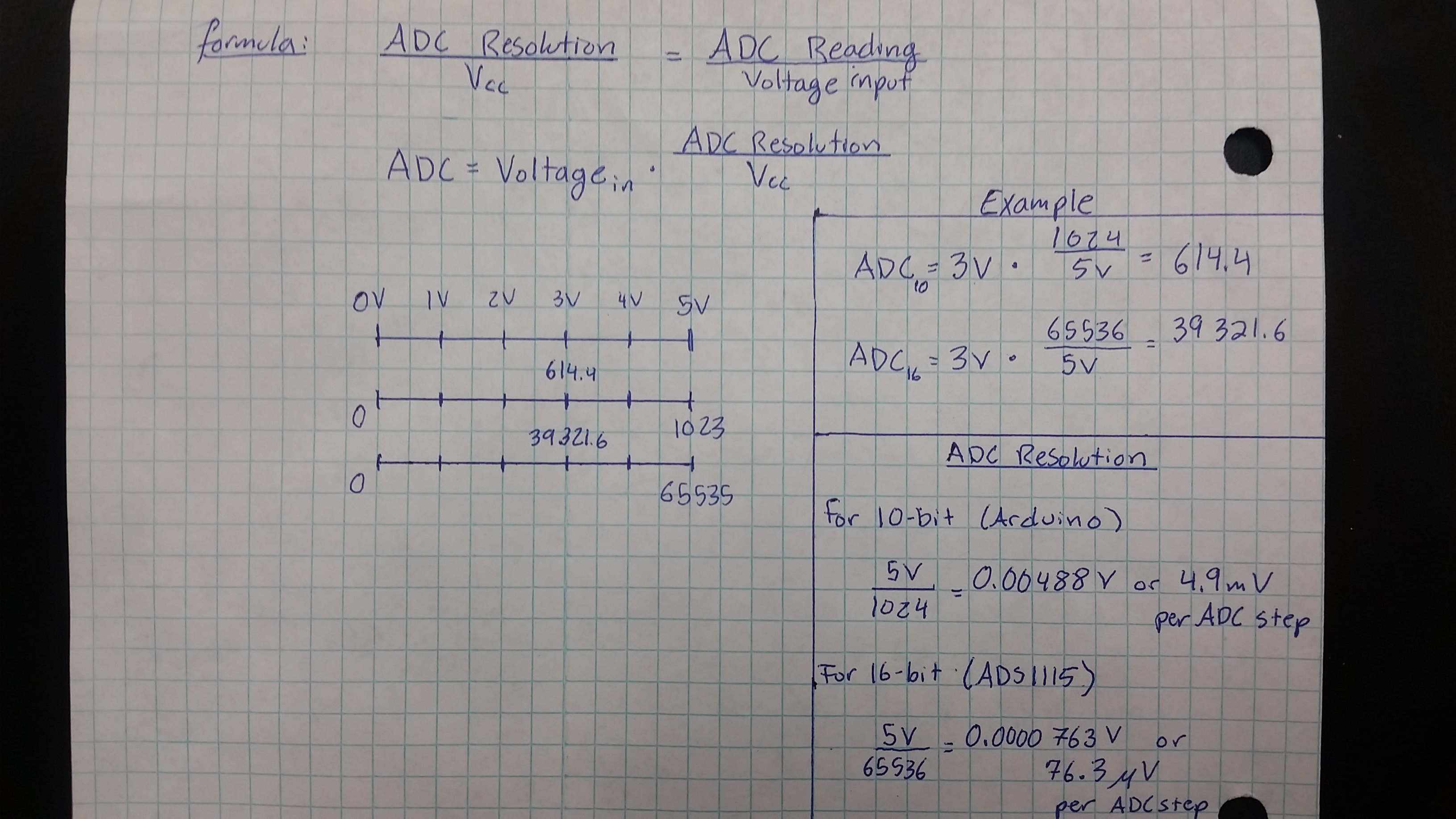
This whole project revolves around this little board. In short, it is an Analog-to-Digital Converter (ADC) with 16-bits of resolution with a Programmable Gain Amplifier (PGA). You may be thinking to yourself, "but doesn't the Arduino already have and ADC built-in??" and the answer is "Yes", however it has only 10-bits of resolution. So what is the big deal about this "resolution" thing I keep mentioning? Well when you want to bring information in from the outside world to a micro-controller you use a sensor. The problem is, especially in the case of temperature, the signal is in the form of a voltage who's value is between a minimum and a maximum value. In the case of an Arduino and peripherals, this range is from ground (0 Volts) to Vcc (on the order of 5 Volts). Other voltage ranges may be used with an Arduino but a voltage divider network would need to be employed to prevent the maximum input voltage from exceeding Vcc; more on that in another tutorial! As you know, micro-controllers process information in the form of digital signals who have only two states, HIGH and LOW or 1 and 0. Therefore, to integrate the two you need an ADC! This ADC converts a voltage into a digital signal by taking a voltage and mapping it to a value between a defined minimum and maximum. This is where ADC resolution becomes inportant if one needs an accurate and reliable measurement. You can see in the hand written image the general formula for ADC conversions as well as a couple examples, but the punch line is on the lower right side. The Arduino's 10-bit ADC takes steps of 4.9mV where-as the ADS1115 takes steps of 76.3 uV and as you will see later, the smaller the ADC step, the better!
Note: The ADC resolution is found by raising 2 to the power of the number of bits. For example 2^(16) = 65536.
Assembly Time!
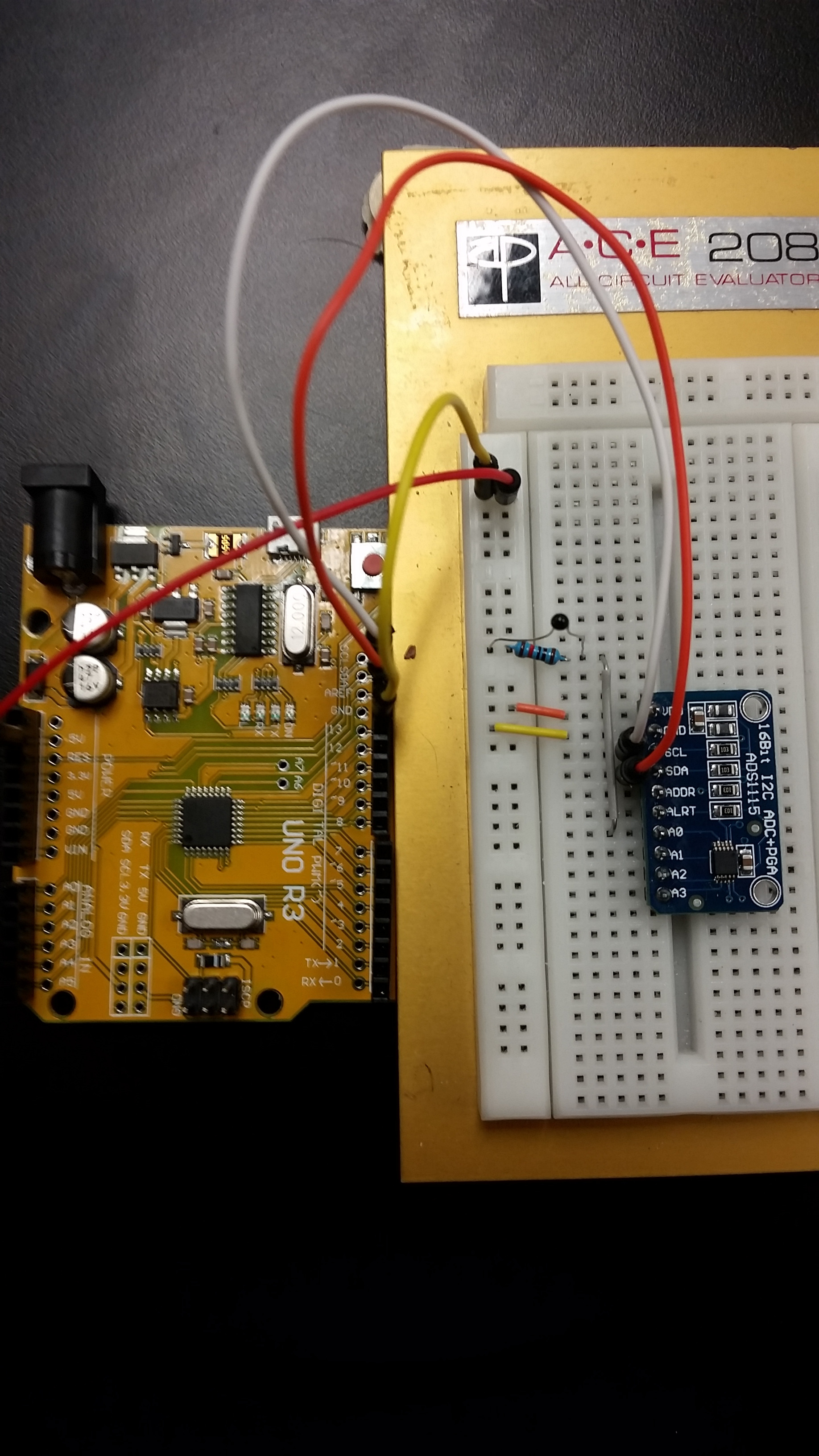
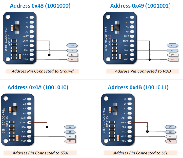
The circuit is quite straight forward, just ensure that the SDA and SCL wires are in their correct places. Also, although as you will see in the code, the default I2C address is 0x48, but you can set the address to one of four so that you may connect up to 4 ADS1115 boards to a single I2C setup! Check out the image above to see how to change the address.
The Code.
First, we have to import the proper library. There are many different ways to do this but since this one was written by the fine folks at Adafruit I found the most effective way to be through: Sketch -> Include Library -> Manage Libraries then type "Adafruit_ADS1X15" and click install. Then, copy and paste this sketch borrowed from:
http://henrysbench.capnfatz.com/henrys-bench/ardui...
Which is an excellent resource for more information on the ADS1115.
***************************
#include <Wire.h>
#include <Adafruit_ADS1015.h>
Adafruit_ADS1115 ads(0x48);
float Voltage = 0.0;
void setup(void) {
Serial.begin(9600);
ads.begin();
}
void loop(void) {
int16_t adc0; // we read from the ADC, we have a sixteen bit integer as a result
adc0 = ads.readADC_SingleEnded(0);
Voltage = (adc0 * 0.1875)/1000;
Serial.print("AIN0: ");
Serial.print(adc0);
Serial.print("\tVoltage: ");
Serial.println(Voltage, 7);
Serial.println();
delay(1000);
}
***************************
If you open the serial monitor, you should see the ADC value as well as the Voltage at analog pin A0 (on the ADS1115).
Now Let's Modify It.
So now that we have a proof of concept working, let's use it to give us some meaningful outputs. Here is the modified code to output the actual temperature in Celcius.
****************************
#include <Wire.h>
#include <Adafruit_ADS1015.h>
Adafruit_ADS1115 ads(0x48);
float Voltage = 0.0;
int thermistor_25 = 10000;
float refCurrent = 0.0001;
void setup(void) {
Serial.begin(9600);
ads.begin();
}
void loop(void) {
int16_t adc0; // we read from the ADC, we have a sixteen bit integer as a result
adc0 = ads.readADC_SingleEnded(0); // Read ADC value from ADS1115
Voltage = adc0 * (5.0 / 65535); // Replace 5.0 with whatever the actual Vcc of your Arduino is
float resistance = (Voltage / refCurrent); // Using Ohm's Law to calculate resistance of thermistor
float ln = log(resistance / thermistor_25); // Log of the ratio of thermistor resistance and resistance at 25 deg. C
float kelvin = 1 / (0.0033540170 + (0.00025617244 * ln) + (0.0000021400943 * ln * ln) + (-0.000000072405219 * ln * ln * ln)); // Using the Steinhart-Hart Thermistor Equation to calculate temp in K
float temp = kelvin - 273.15; // Converting Kelvin to Celcuis
Serial.print("AIN0: "); // Print ADC value to Serial Monitor
Serial.print(adc0);
Serial.print("\tTemperature: "); // Print temperature to Serial Monitor in Celcius
Serial.println(temp, 7);
Serial.println();
delay(500); // Change how often the sketch outputs reading
}
****************************
This should get you within a degree or so in Celcius and adjustments may be made for your set-up to fine tune the accuracy.
Conclusion
That should be enough to get you going. Here are a few links that I found very helpful in setting this up:
https://learn.sparkfun.com/tutorials/analog-to-dig...
http://henrysbench.capnfatz.com/henrys-bench/ardui...
https://cdn-shop.adafruit.com/datasheets/ads1115.p...
https://www.adafruit.com/products/1085
Github:
https://github.com/adafruit/Adafruit_ADS1X15
Next, we will establish communication with Matlab and create an App to collect temperature data on multiple channels!
Please comment or pm if you have any questions, suggestions, or criticisms!