15$ LoRa Gateway/Node ESP8266 Build PCB 3cmX8cm Size
by AkarshA2 in Circuits > Arduino
8020 Views, 22 Favorites, 0 Comments
15$ LoRa Gateway/Node ESP8266 Build PCB 3cmX8cm Size

Hey, what's up, guys? Akarsh here from CETech.
Today we are going to make a project which is a simple LoRa node and you can even use it as a single channel gateway.
Here the microcontroller that I used is the ESP8266, which is connected to LoRa boards of 433MHz(Ra-02 by Ai-Thinker), I have also attached an OLED display to the PCB so that the packet information is visible.
To make things simpler I have designed a PCB which you can get manufactured for soldering.
I have also made a video about building this project in detail, I recommend watching that for better insight and detail.
Parts


I got the majority of the parts for my build from LCSC.
You will need:
2) ESP8266
3) OLED display
4) Passive components like resistors and capacitors
You would require the PCB to solder these components which we will see in the next step.
Downloads
Get the Project PCB Manufactured

You must check out JLCPCB for ordering PCBs online for cheap!
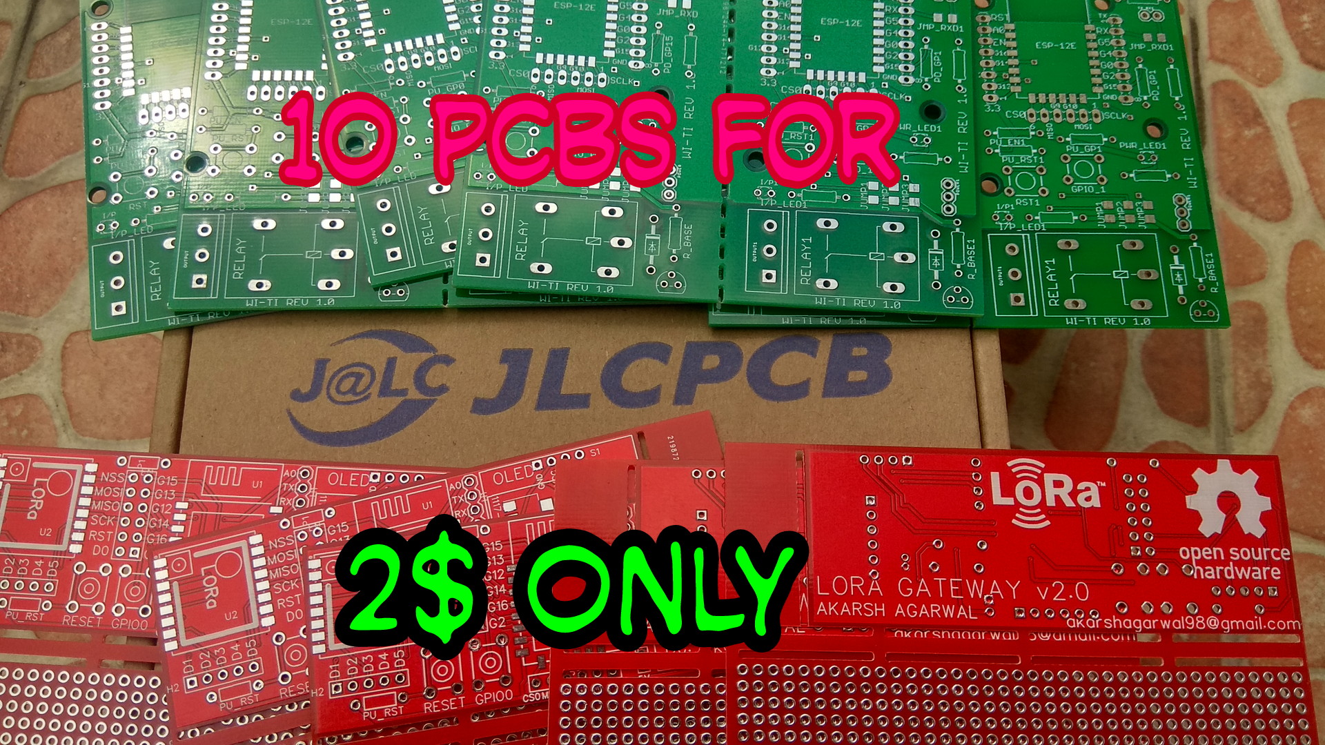
You get 10 good quality PCBs manufactured and shipped to your doorstep for 2$ and some shipping. You will also get a discount on shipping on your first order. To design your own PCB head over to easyEDA, once that is done upload your Gerber files onto JLCPCB to get them manufactured with good quality and quick turnaround time.
Download the Gerber file:
Downloads
Connections (THEORY)


Mainly there are 4 aspects in connections here:
1) ESP8266 just to function correctly needs some pull up and pull down the connection for G0, G15, EN and RST.
2) Ra-02 and the ESP8266 modules are connected to each other using the SPI protocol
3) OLED and the ESP8266 connect to each other using the I2C bus
4) All the modules need to be connected to power rails for them to operate.(Obvious :P)
Soldering


Solder all the components to the PCB.
I would suggest to solder the low height components on the PCB first and then move to components with more height like the headers etc.
Before powering the module test all the connections using a multimeter for bad solder joints and short circuits.
Coding the Module


1) Download the code from here.
2) Open the code in the Arduino IDE.
3) Connect the PCB to the computer using the CP2102 USB to serial converter or any other similar device.
4) Reset the ESP8266 module while pulling the GPIO0 low (keep the G0 button pressed while reset).
5) Now hit the upload button on the IDE. Upload might fail once or a couple of times so you must try 2-3 times in case of failure.
6) Disconnect the USB to serial adapter and connect the OLED display if you haven't yet.
7) Program the other part of the project Reciever/Transmitter
Testing Time!!


Once you've coded both the modules you can attach them to power.
In my case I attached my transmitter to a power bank, the receiver to a laptop for access to a serial monitor.
As soon as I powered the transmitter I started to see messages on the serial monitor connected to the receiver.
Mine works like a charm!