12V Out From Any Quickcharge Compatible Powerbank
by DIY ElectroVids in Circuits > Arduino
5772 Views, 2 Favorites, 0 Comments
12V Out From Any Quickcharge Compatible Powerbank
 Compatible Powerbank)
The application of a quickcharge powerbanks is not only for charging of phones, but also serves as a backup power supply for 12V devices such as modems at home.
More details can be found in this blog:
http://blog.deconinck.info/post/2017/08/09/Turning...
Check the specifications of your QC (Quick Charge) powerbank. Do not overload your powerbank, I will not be held responsible if you damage your powerbank or your Arduino.
Watch my video at:
Supplies
Things you will need:
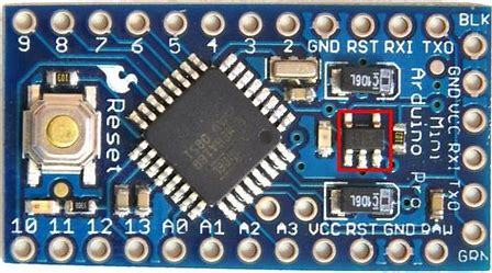
-Arduino pro mini 3.3V, 8MHz
-Wire cutters
-Wire strippers or knife
-Soldering Iron and solder
-computer with Arduino software
-Voltage regulator (LM317 or LM317LZ)
-Soldering paste (optional)
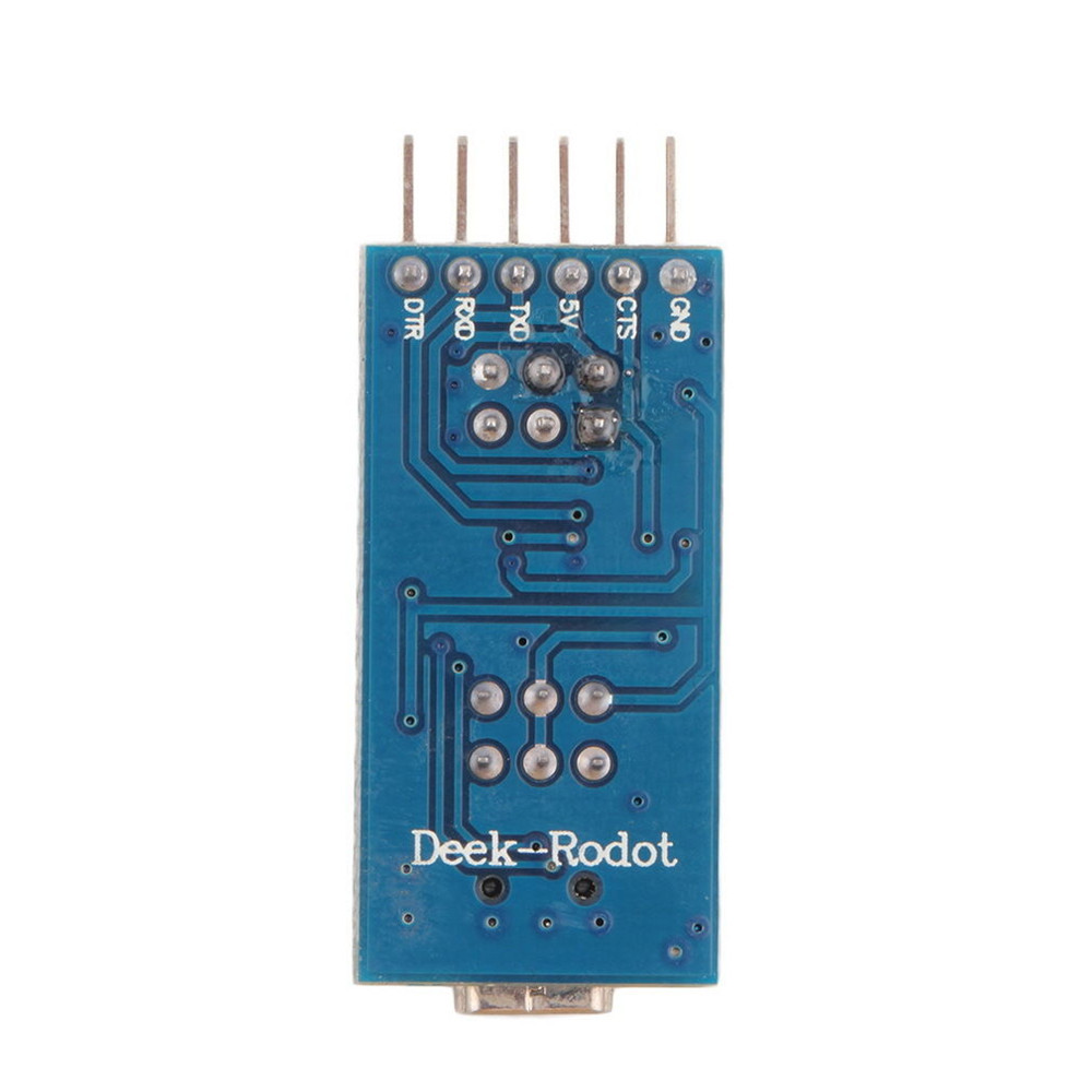
-FTDI breakout board: https://www.lazada.sg/products/basic-breakout-boar...
-2.2k ohm and 10k ohm resistors
-10uF 25V and 100uF 35V Capacitors
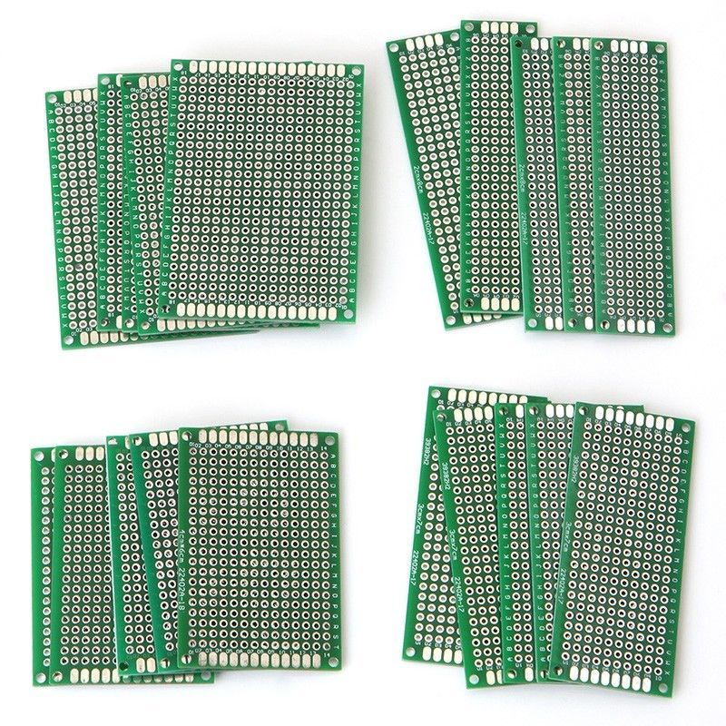
-prototyping PCB board
Note: All of the items listed are either bought from my local electronic parts store or found at home except the FTDI breakout board
Strip USB Cable
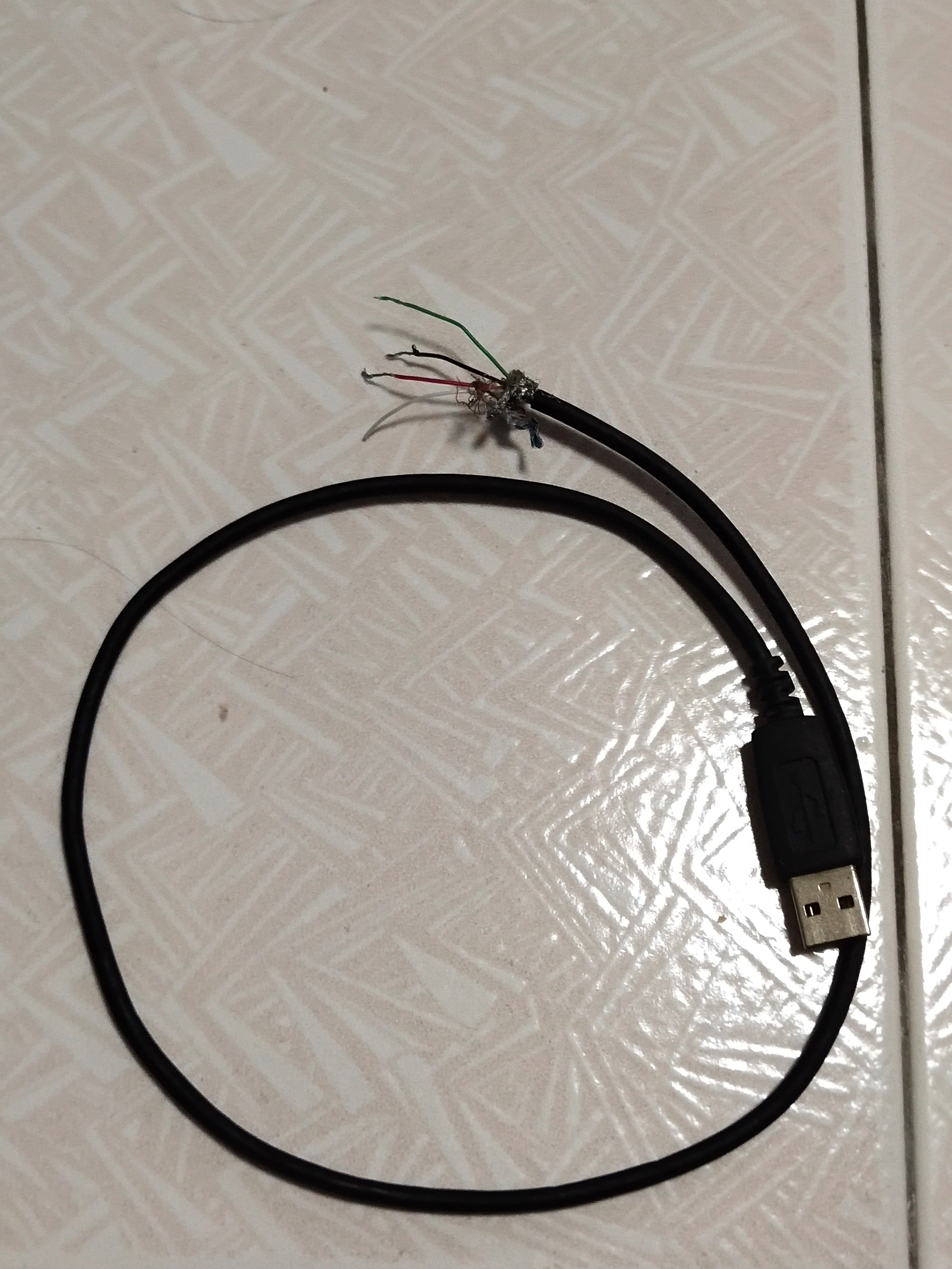
Find any unused USB cable or any USB vable with spoilt connectors. Cut the cable into two and strip the insulation. Leave one end with the male USB-A Connector and the other end with 4 striped wires. The striped cable is as shown in the picture. Better to use cable with thicker wires.
You should see 4 wires:
Red- Vcc
Green- Data +
White- Data -
Black- Ground
Gather All the Required Components
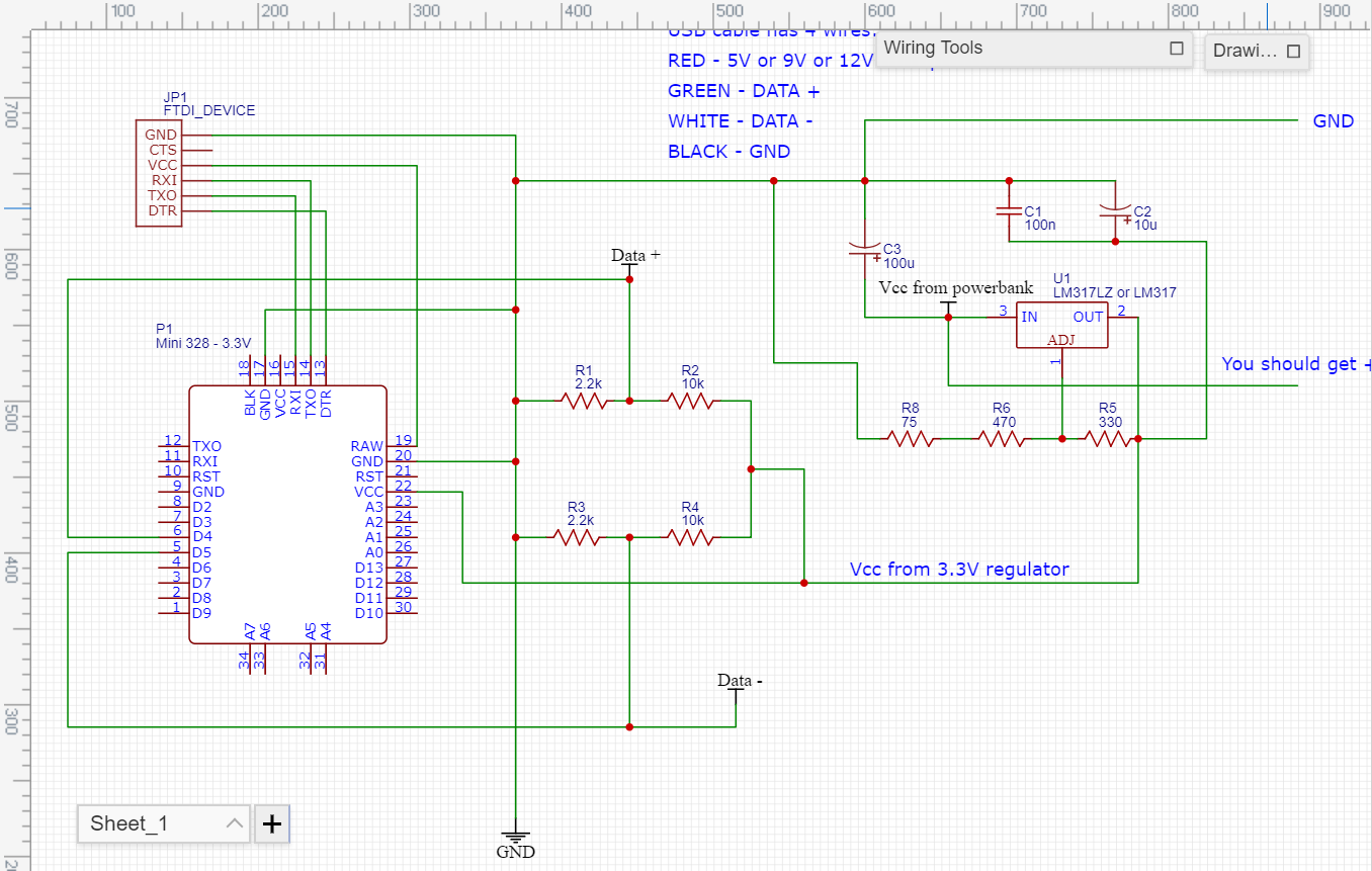
Gather all your required components and build the circuit as shown in the schematic.
The link to the schematic is shown below:
Build the 3.3V Voltage Regulator
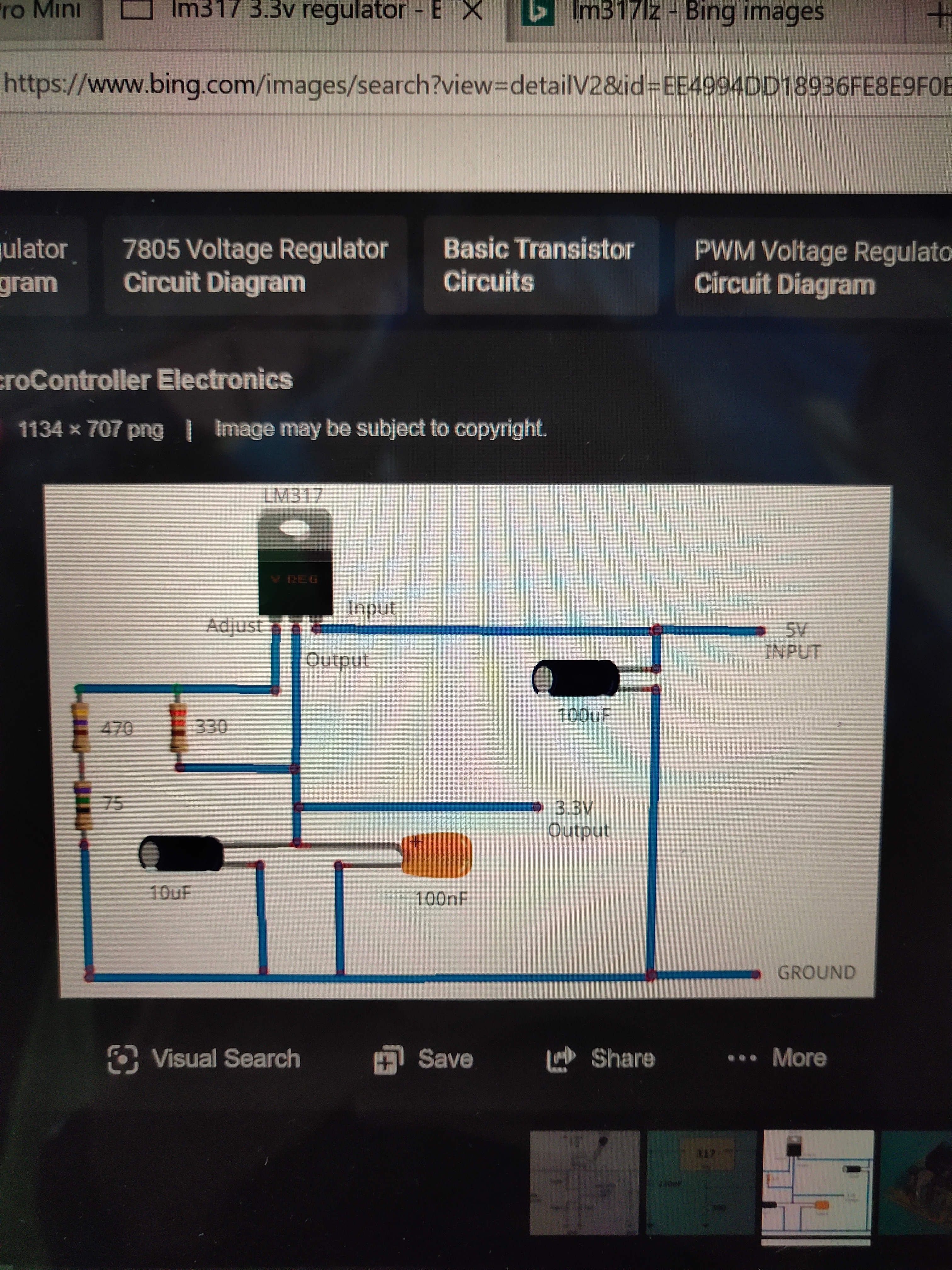
The external voltage regulator works for voltages above 12V. The input voltage limit into raw pin on the Arduino pro mini is 12V.
I didn't design the 3.3V regulator circuit.
For more details, see the link below:
Soldering on the 3.3V Arduino Pro Mini
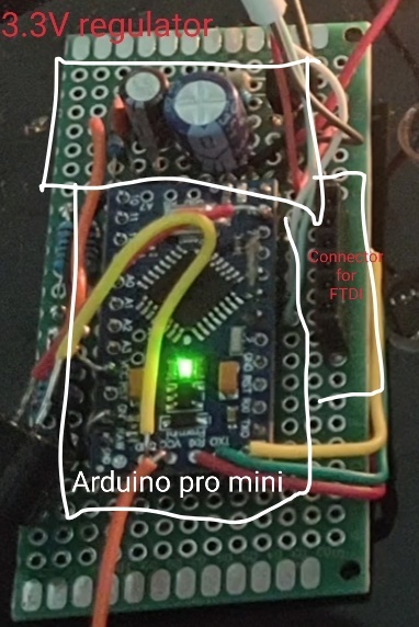
Solder the Vcc pin of 3.3V arduino pro mini to output of the 3.3V voltage regulator that you already built. Refer to schematic shown in step 2.
Coding
To begin coding, download the quick charge library.
You can download on: https://github.com/vdeconinck/QC3Control/archive/v...
or you can launch the Arduino software on your computer and update to the latest version of the library in the Library Manager as well. The steps are as follows:
1. Open the Arduino IDE (1.5 or above).
2. In the tool-bar click Sketch -> Include Library -> Manage Libraries...
3. Type in the search bar "QC3Control".
4. The QC3Control library should show.
5. **Click on it** and click Update. 6. Done!
Once the quickcharge library is downloaded, you can see some example sketches.
Download "QC_volt_transform.txt", that's my code. You can copy and paste all contents in your Arduino Sketch.
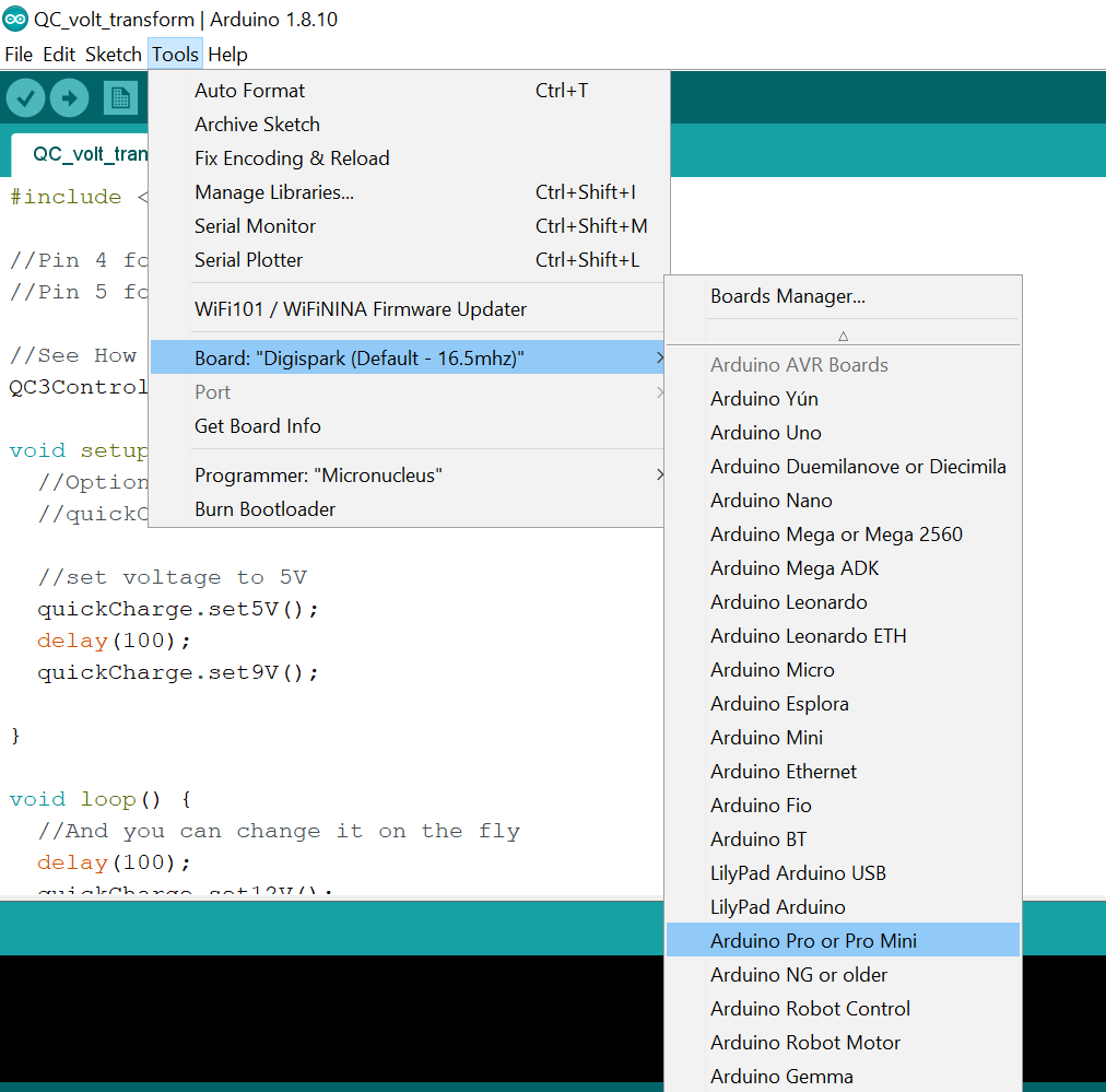
For 3.3V pro mini, go to tools -> boards -> Arduino pro or pro mini
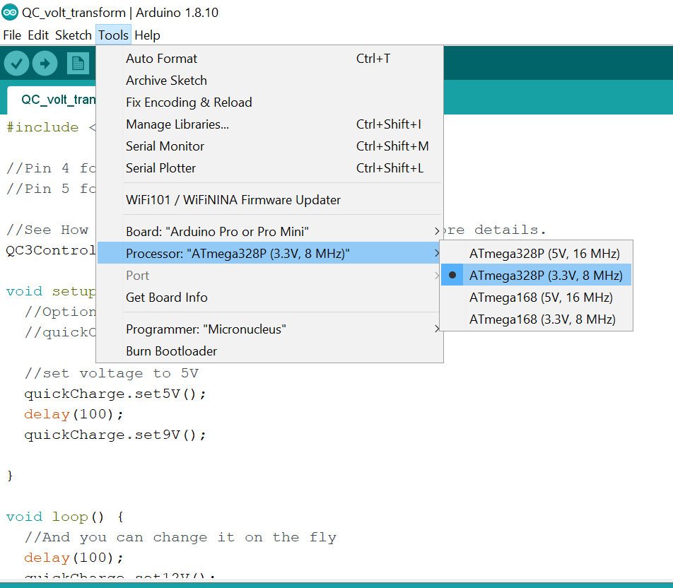
then go to tools -> processor -> ATmega328P (3.3V, 8 MHz)
After setting up your board, proceed to upload the Sketch into your device and test your device.
Downloads
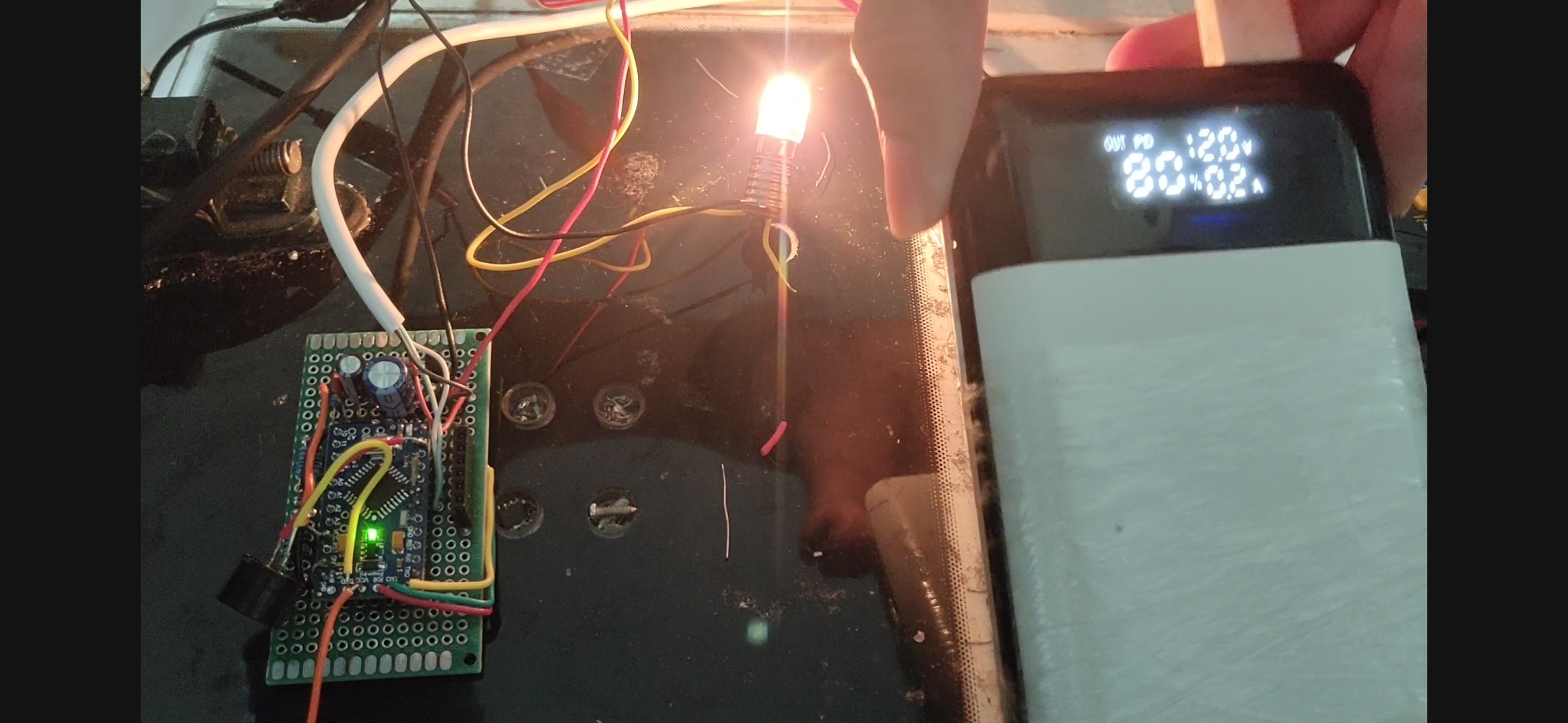
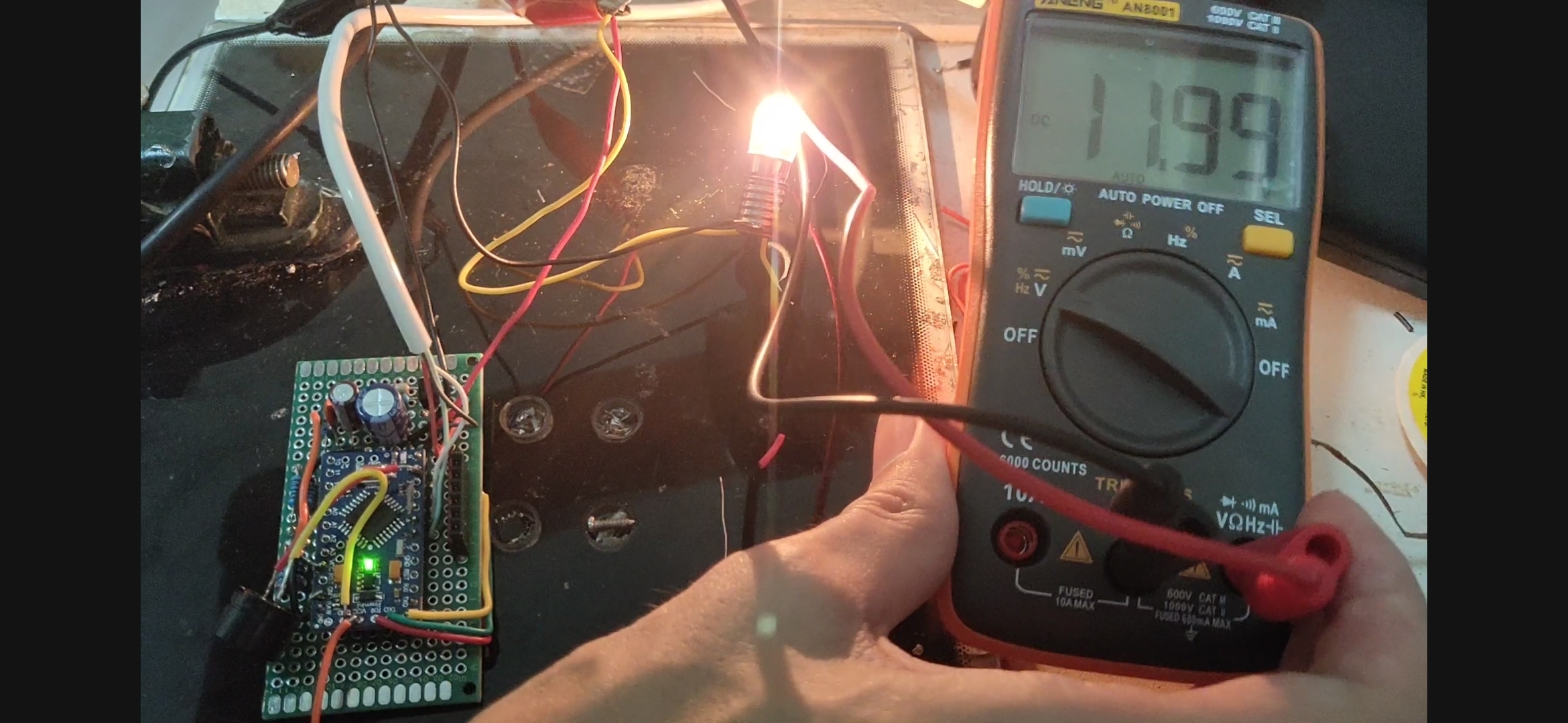
Testing
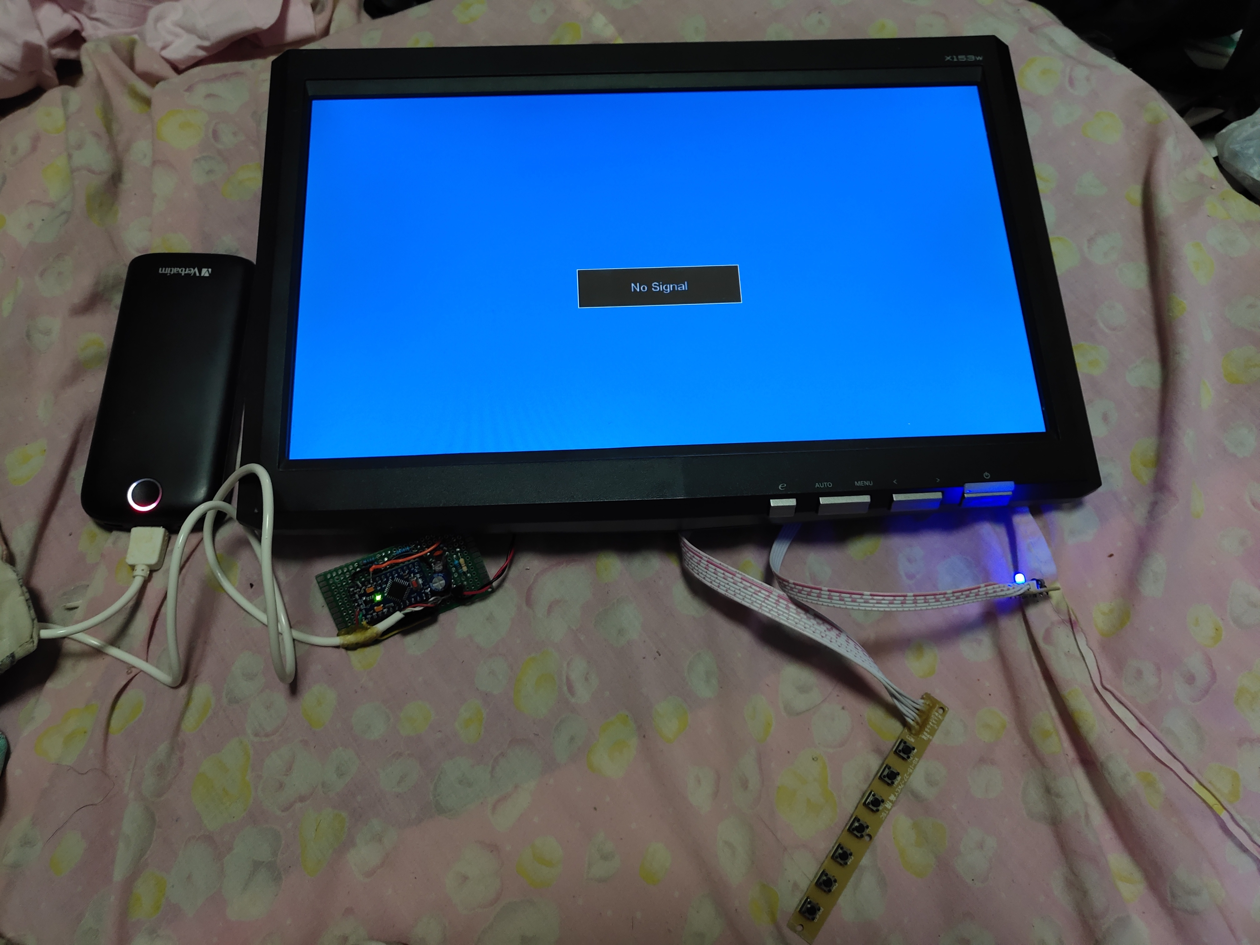
Once the device works, and you confirmed that are getting 12V out from your quickcharge powerbank, you can connect or solder a 2.1mm DC barrel jack connector on the output. You can install whatever connectors you want on the output depending on your application. For me, I used a 2.1mm DC barrel jack connector to test my 12V monitor. Though it powers up the monitor, it draws 1.5A, that is near the current limit of a typical QC powerbank. Do not overload your powerbank, I will not be held responsible if you damage your powerbank.