123D Modeling for 3D Printing
by sath02 in Workshop > 3D Printing
28566 Views, 145 Favorites, 0 Comments
123D Modeling for 3D Printing
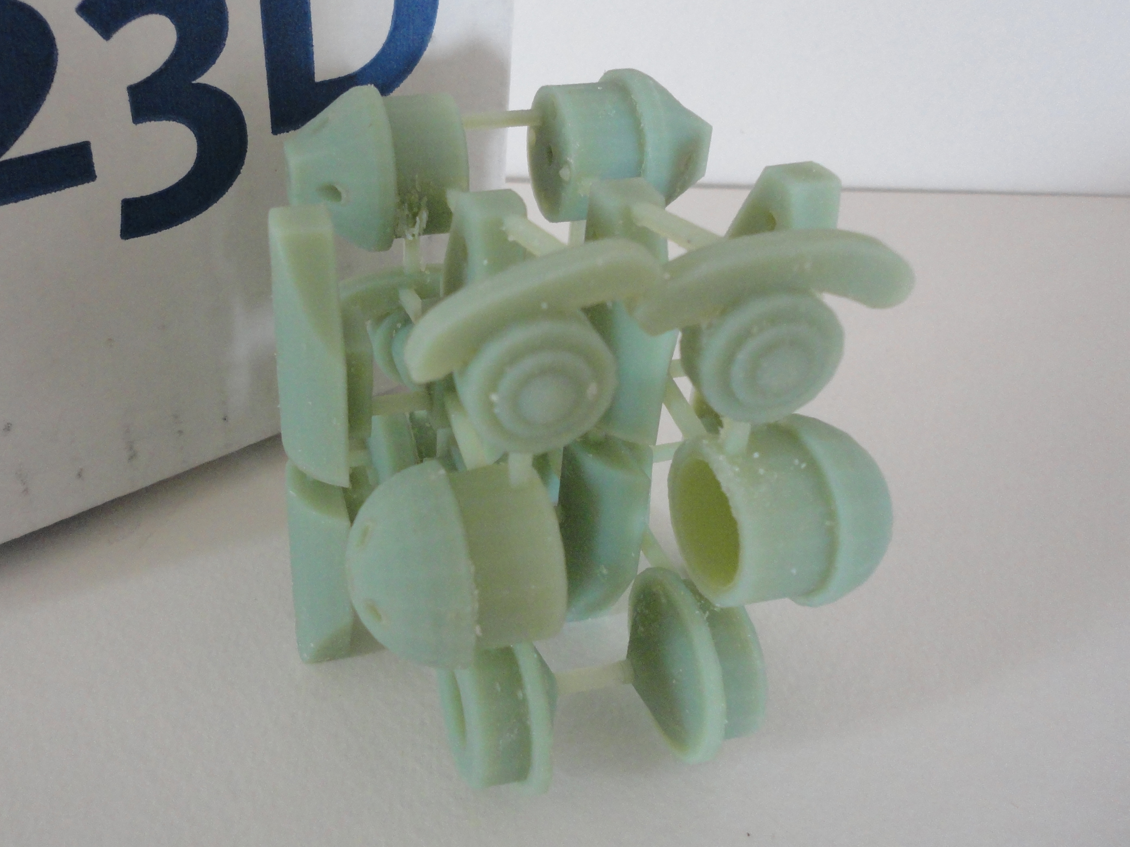
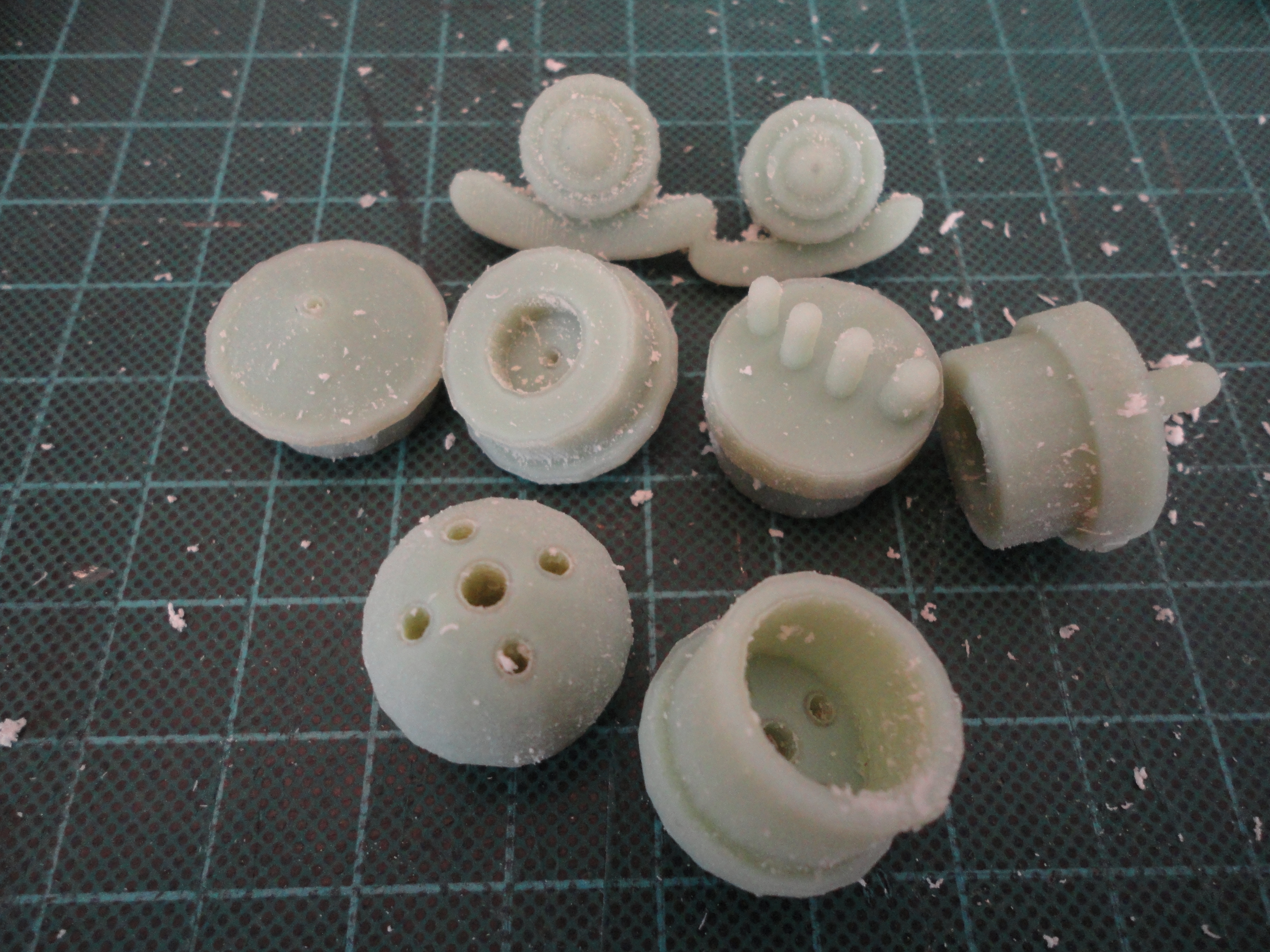
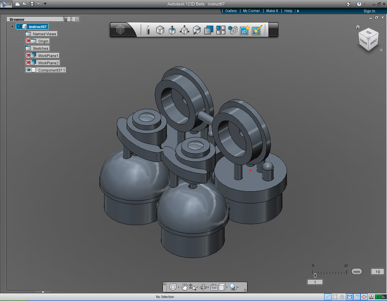
I got a chance to play with Autodesk's 123D application. I spent sometimes to get myself familiar with 123D, and found that it was very easy to use with a lot of features that I could use to create a professional quality 3D models.
This hands-on tutorial is written for anyone who want to make 3D Print.
In this tutorials, you will learn to use 123D through a series of hands-on exercises.
After reading this tutorial, you can use 123D to visualize designs of the things that will actually be built. You will be guided through the basics of 3D manipulation in 123D, and the principal ideas involved in displaying complex 3D objects, and will be ready to create the simple objects that will get you that first 3D Printing object. You will learn how to save and export files directly from 123D program to send to fabricator, such as "Free 3D Printing" Group (Now, closed.) or anyother 3D Fabricators.
On the way, you get to do something you can see with your “looking glass”, you can create 3D parts, robots, objects and subjects of any type.
Goals
- Sketch/design the models.
- Getting to know the 123D application.
- Use 123D application to create various small 3D models of robot's parts, ears, eyes, shoulders and hands.
- Combine (join) these parts together into one single piece.
- Submit the model to the Instructables' "Free 3D Printing" Group, or to 3D Print fabricators.
By combining (joining) small individual 3D Models together, either from the same project or from different project. We could save time and do not have to submit each part individually. And we could avoid waiting for each part to be delivered many times before using them in the project(s).
Another benefit of combining (joining) models together is that if the combined model has the size which is smaller than 3x3x3" cube, we could submit the model to "Free 3D Printing" offer to have it made if you are not in a hurry! But you need to write up an instructable and sign up as a member, to qualify.
Not only you could use this methods for "Free 3D Printing" here at instructables, but you could also apply the methods with your 3D model to be done ( but not free) at Shapeway, Ponoko, etc. (which allow you to print a larger 3d model for example a model with a footprint of 4x6", etc.)
Rough Sketches
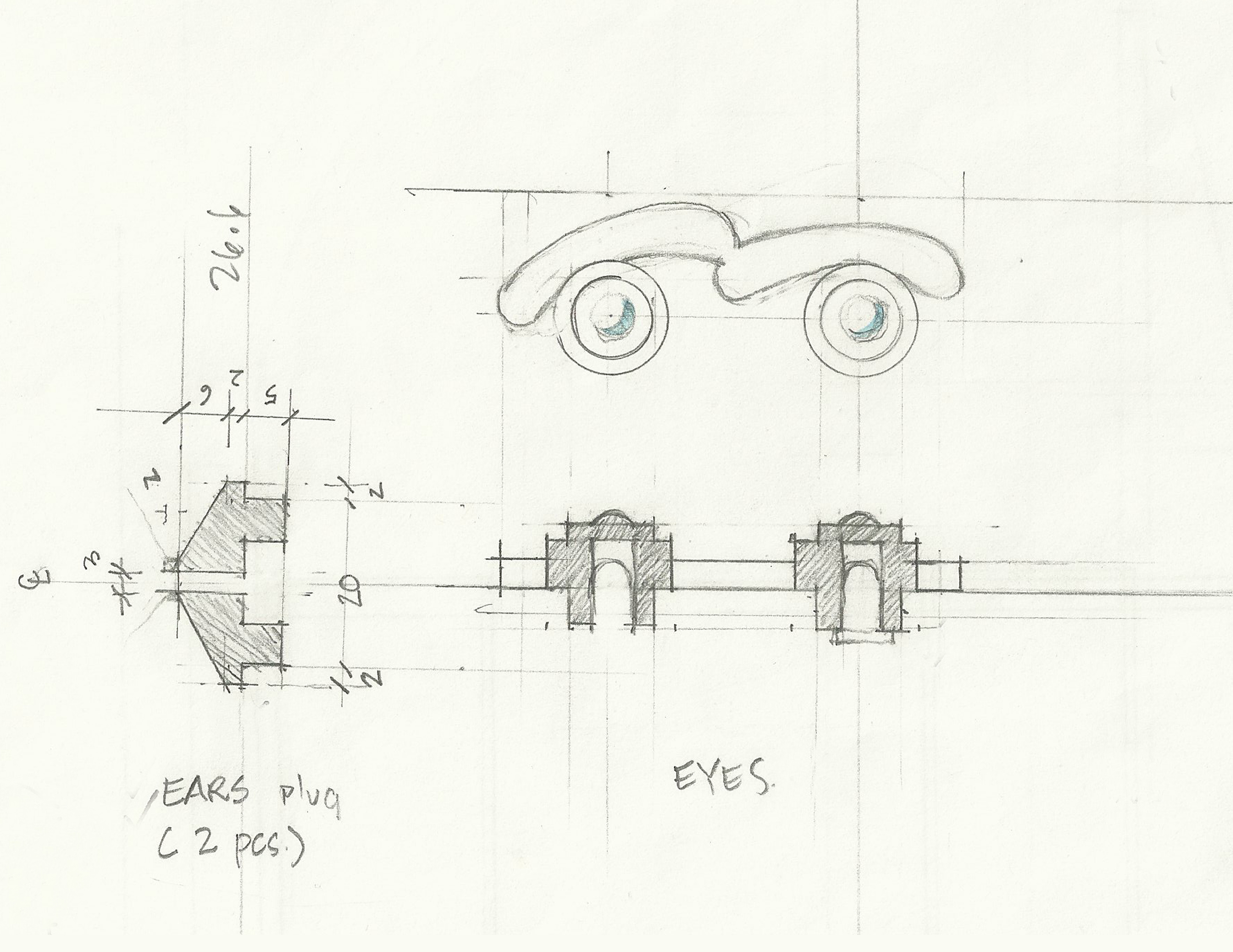
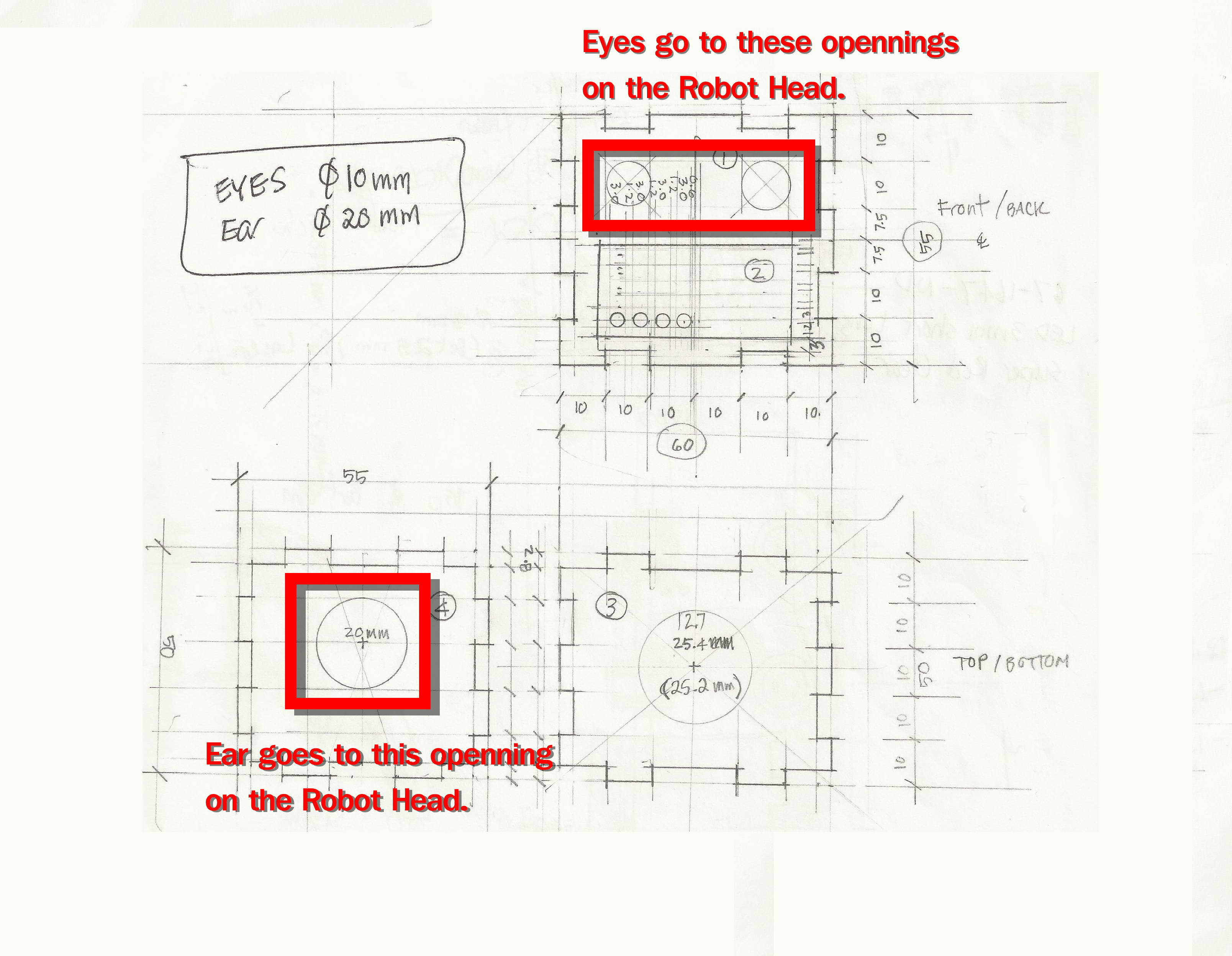
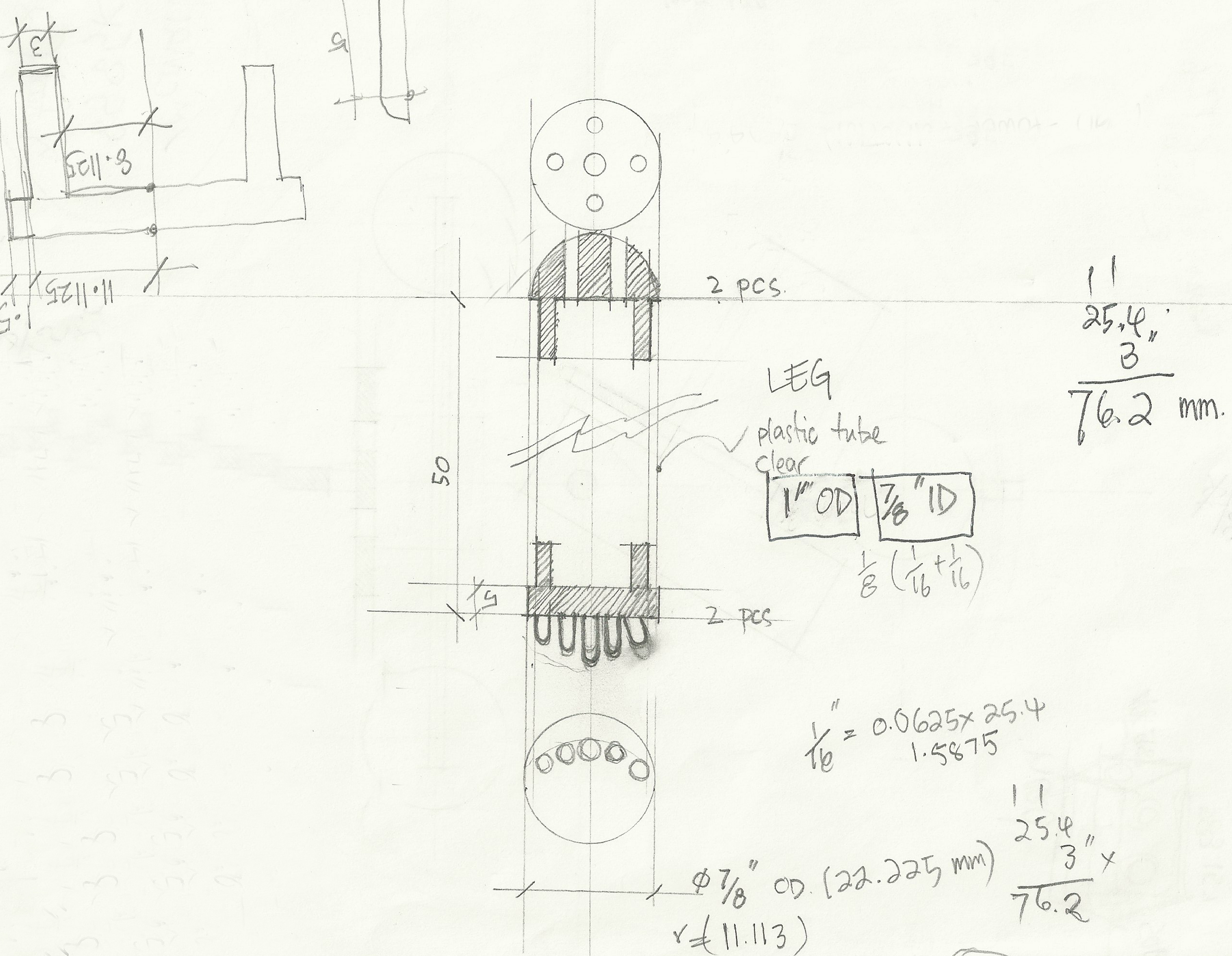
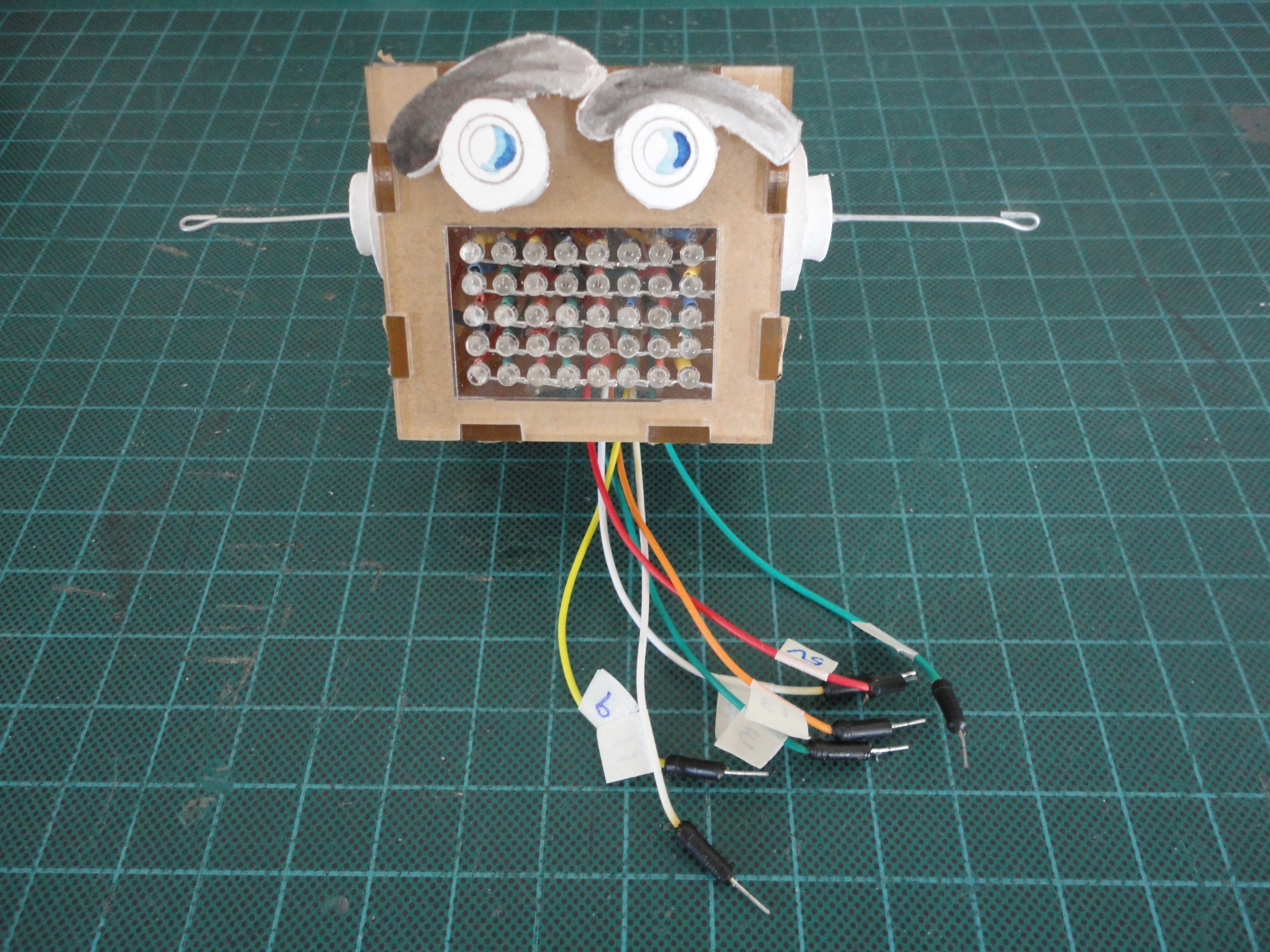
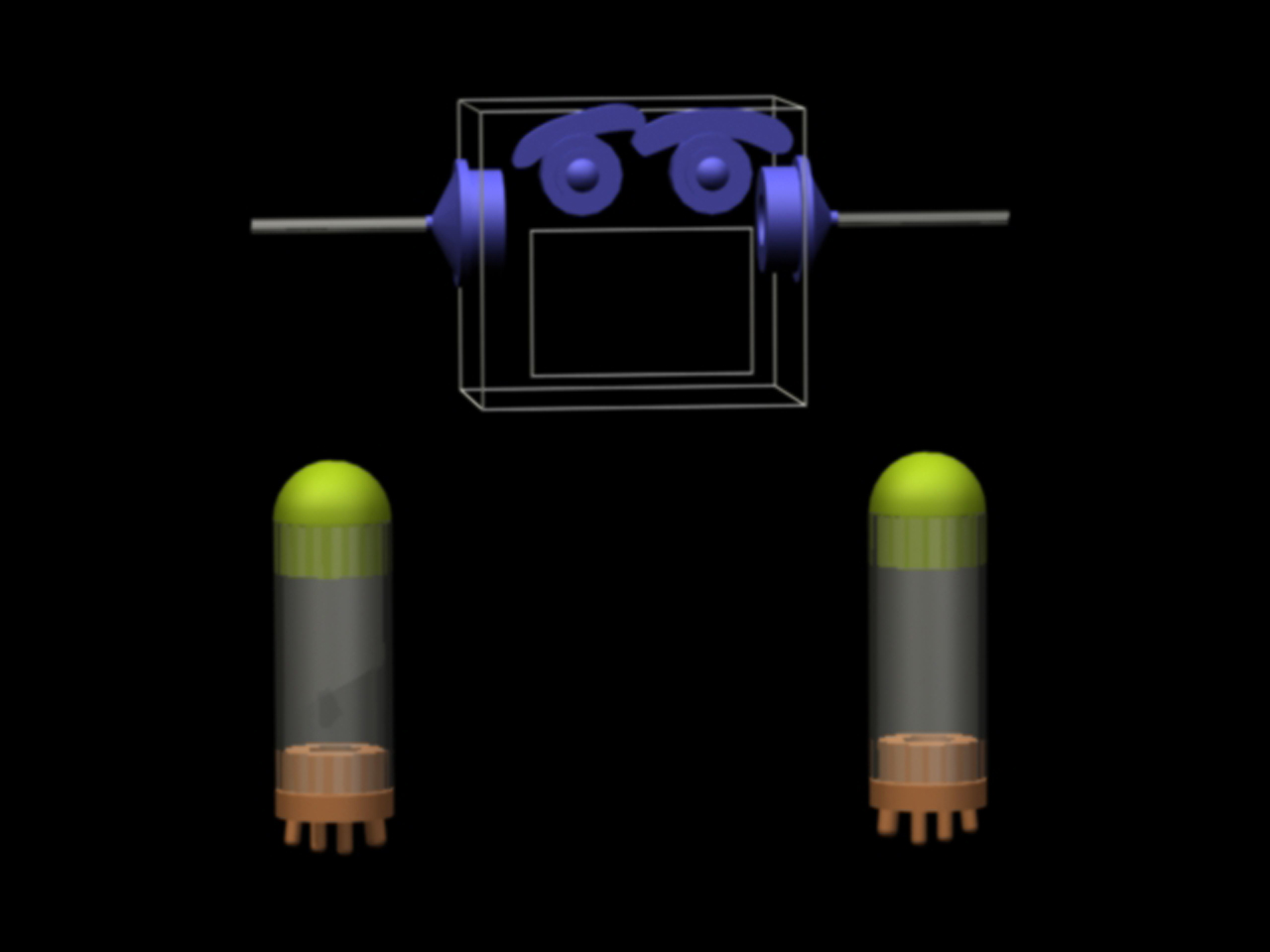
I designed the ears, eyes, shoulders, and hands for my robot project, Put 40 LEDs and Brain into Robot Head.
All the parts are only decorative pieces for the robot, only the eyes that I may want to put the 5mm diameter LEDs inside.
And the parts will be fit into the round existing openning, for example eyes will be fit in 10 mm diameter openning, and ears will be fit in 20 mm diameter openning. And both shoulders and hand will be fitting into round Acrylic tubing with 1" (25.4mm) OD (Outside Diameter) and 7/8" (22.225mm) ID (Inside Diameter) . So the designs will somehow have the round plug attached to one end, as shown in the sketches below.
The Sketches
When I was working on the new project, I usually transfer the idea I had in mind into the paper. Sometimes I only doodling on the napkin, just like other designer/inventor did!
Later I would refined the napkin sketches to realizable design and something that make sense. The other consideration is that the design should compliment the existing object.
Sketches below (no. 1, 2, and 3) are not really "napkin sketches", they were refined sketches. At this stage all the dimensions are in Millimeter.
Create Profiles
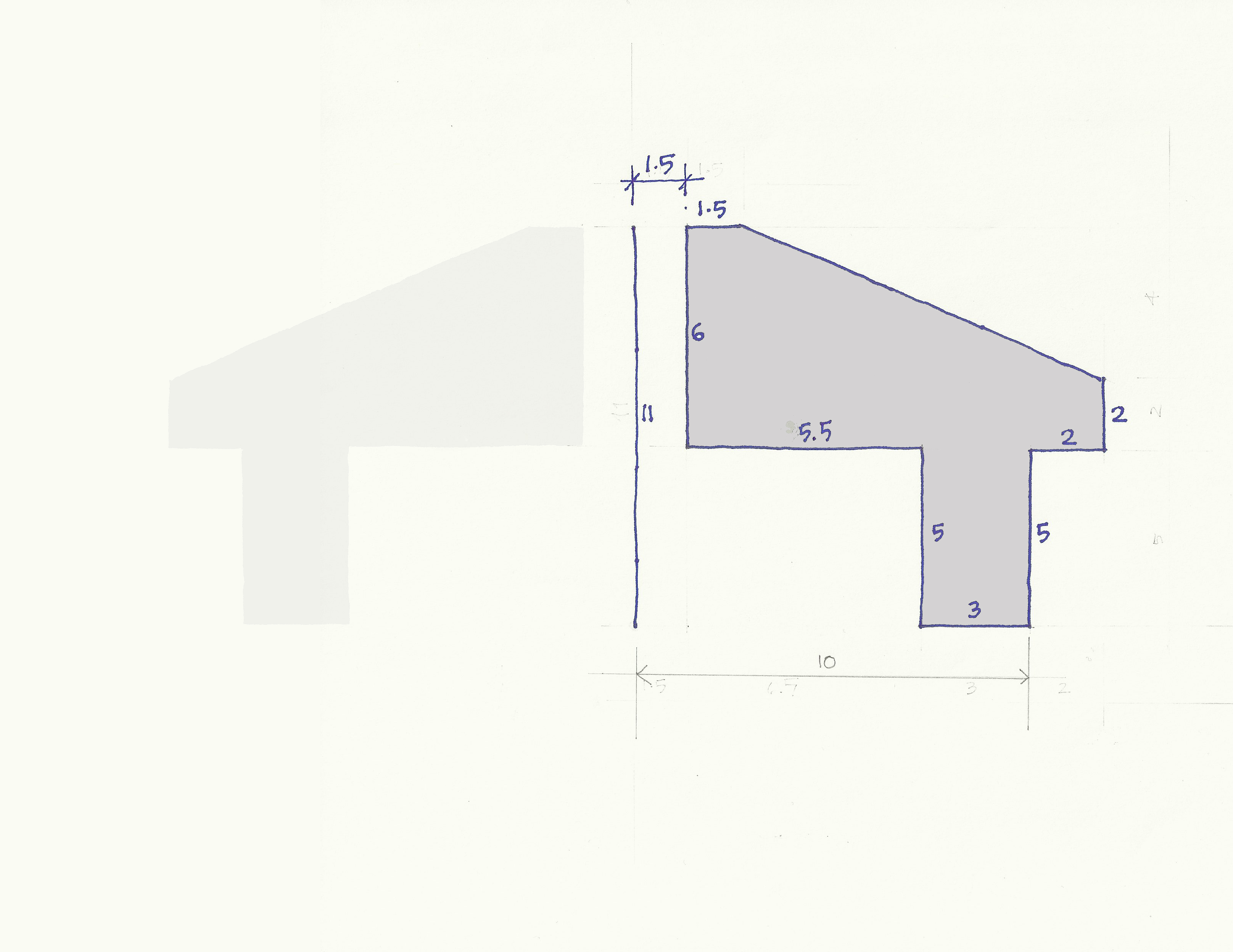
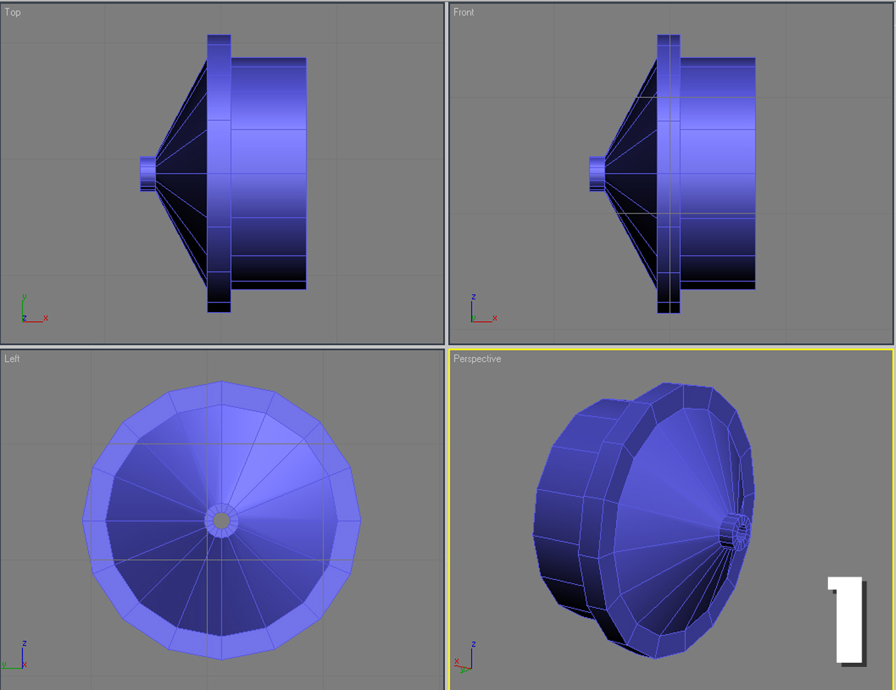
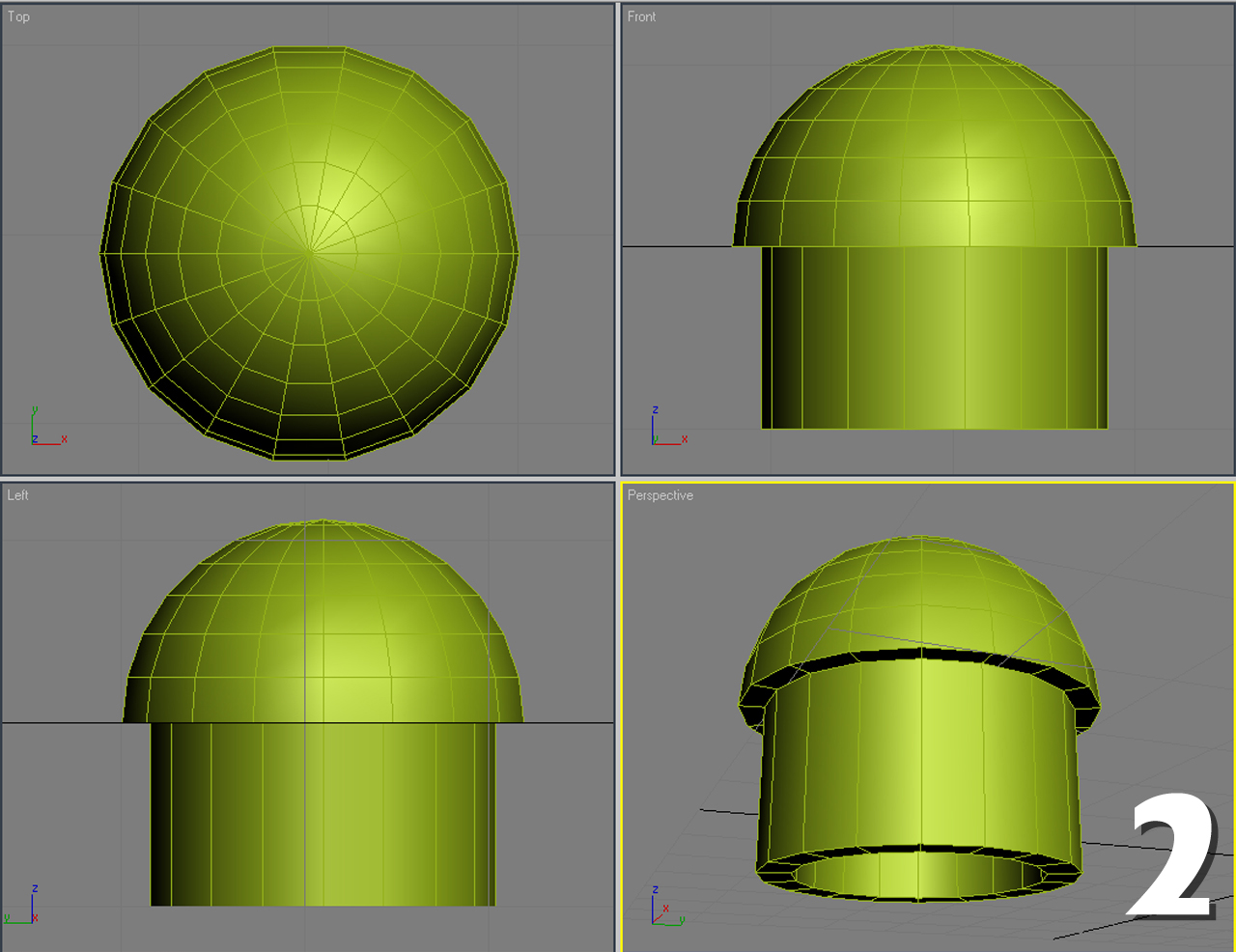
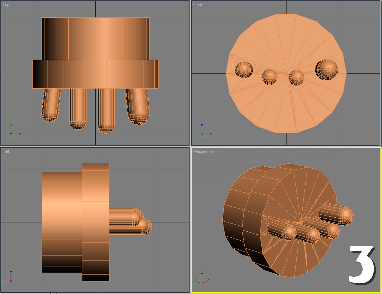
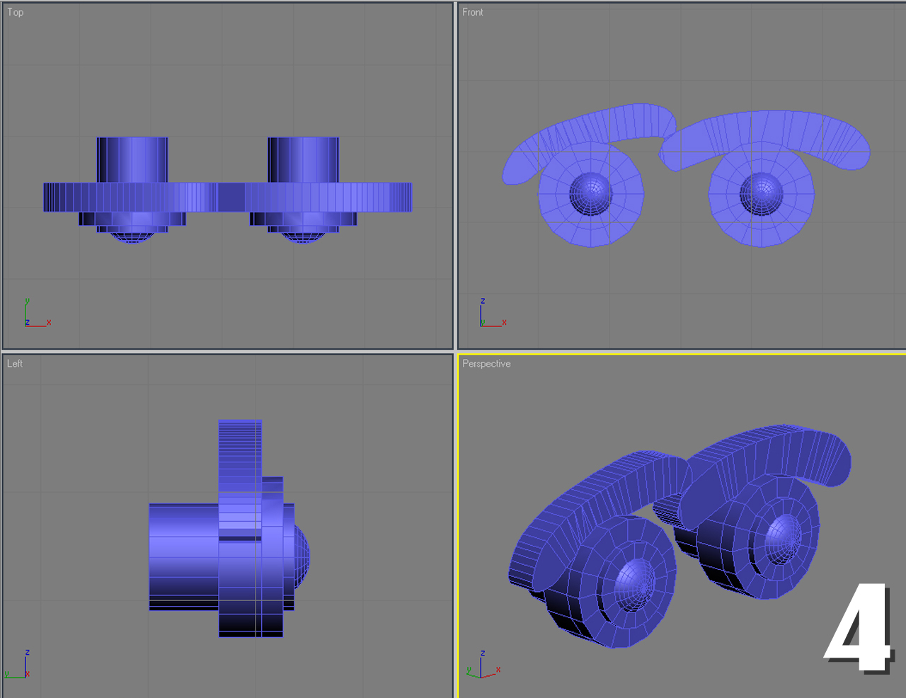
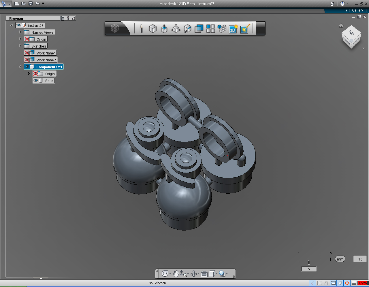
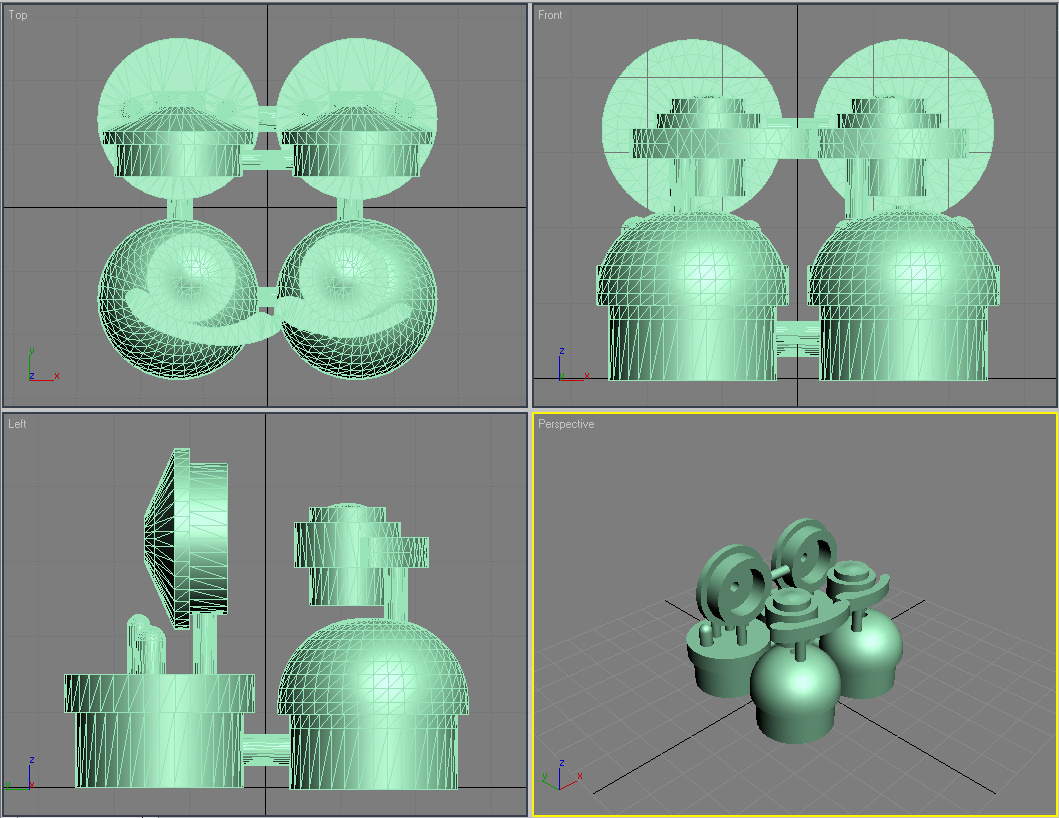
We are going to use 123D to create 3D models of ears, shoulders, hands, and eyes with eyebrows as shown in the four-view renderings ( Top, Front, Left, and Perspective) with the white label no. 1, 2, 3, and 4.
Then we will combine or join them together and send the model to make 3D print (at the Free 3D Printing" Group) as one piece, in one single .stl file. (As shown in the last rendering image in this step.)
The Profiles and Dimensions
In order to make these exercises moving smoothly, I had prepared the sketches of cross-sections with the dimension of the ear, shoulder, hand and finger, and eyes with eyebrows.
We will use them as the guide to draw them and we will transform them into 3D solid model in 123D.
We are going to create all of these 3D models using the dimensions shown on each of the cross-section.
The dimensions all are in Millimeter. (as the default dimension in 123D.)
123D Modeling App.
It was designed to help "maker" who want to be able to create or design 3D object for themselves without using complicate or high end CAD system, or anyone who want to design "digital prototyping" which can be printed out as physical 3D object.
Let us look into the 123D application.
At this point, if you do not have 123D installed, it is a good time to download and install before stepping further.
But if you are already have 123D installed you could skip this step and forwarding to the next step.
For those who has not downloaded and install 123D, just visit 123Dapp.com to get FREE 123D apps.
At the time of writing this instructable, only Windows version is available.
Select the suitable release for your Windows system, 32-bit or 64-bit.
Then follow the instructions to install 123D.
123D APPLICATION
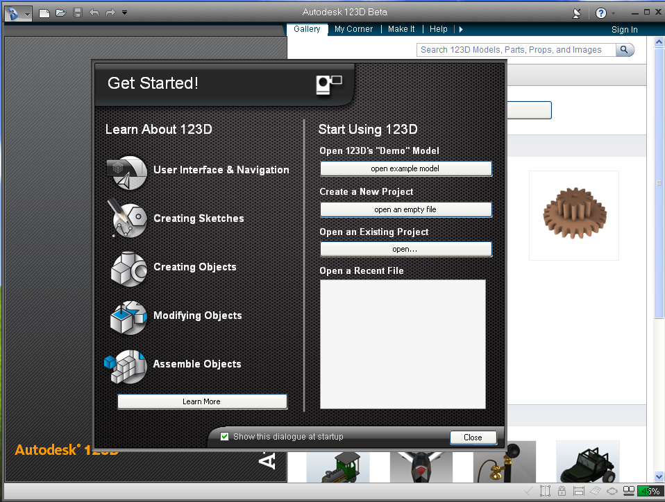
When we open 123D app., First thing we will see is the splash screen.
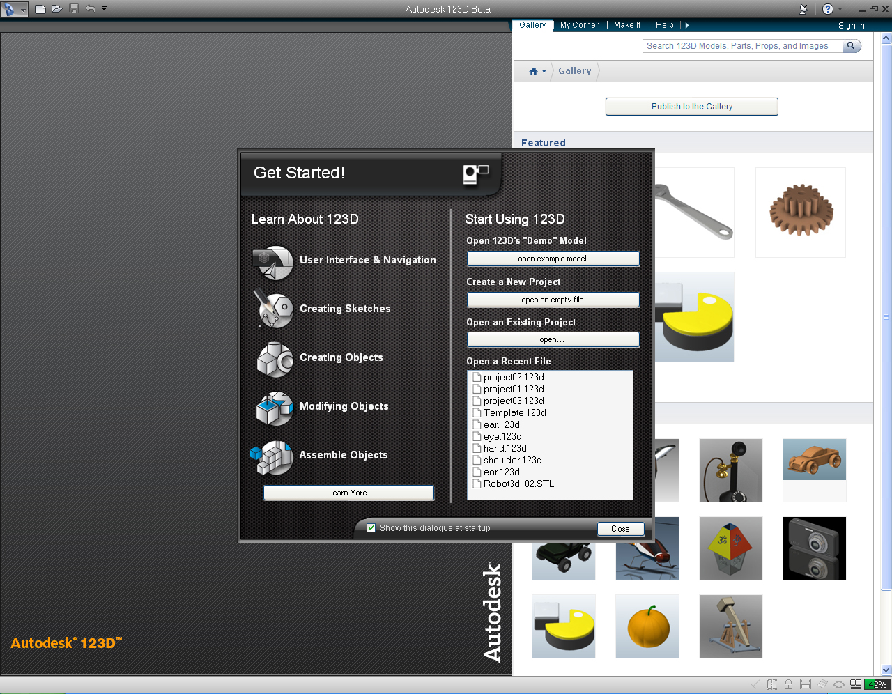
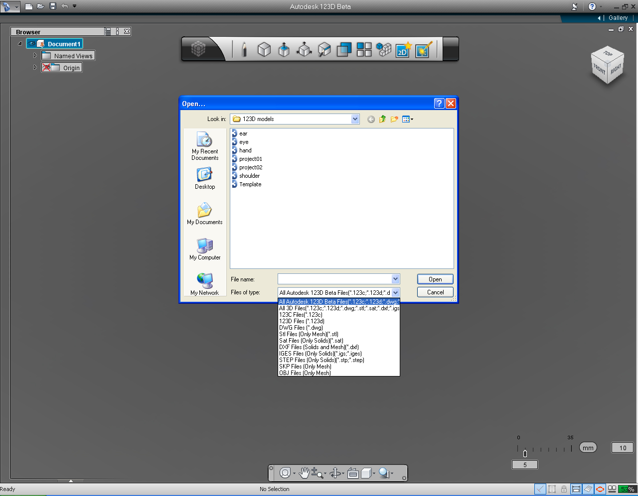
Then the Get Started! window comes up. If you are new to 123D, I suggested to select the "User Interface and Navigation" to learn and get yourself familiar with 123D User Interface. It's just only a few minutes video.
Otherwise, there are these video tutorials that introducing 123D User Interface and Navigations,
Autodesk 123D - Intro to Sketches Video Series: First Sketch, and
123D Tips Video Series: Tip#1: User Interface Tour
(This one was prepared for 123D beta 4, everything pretty much similar to beta9 except it did not have the Snap Bar menu )
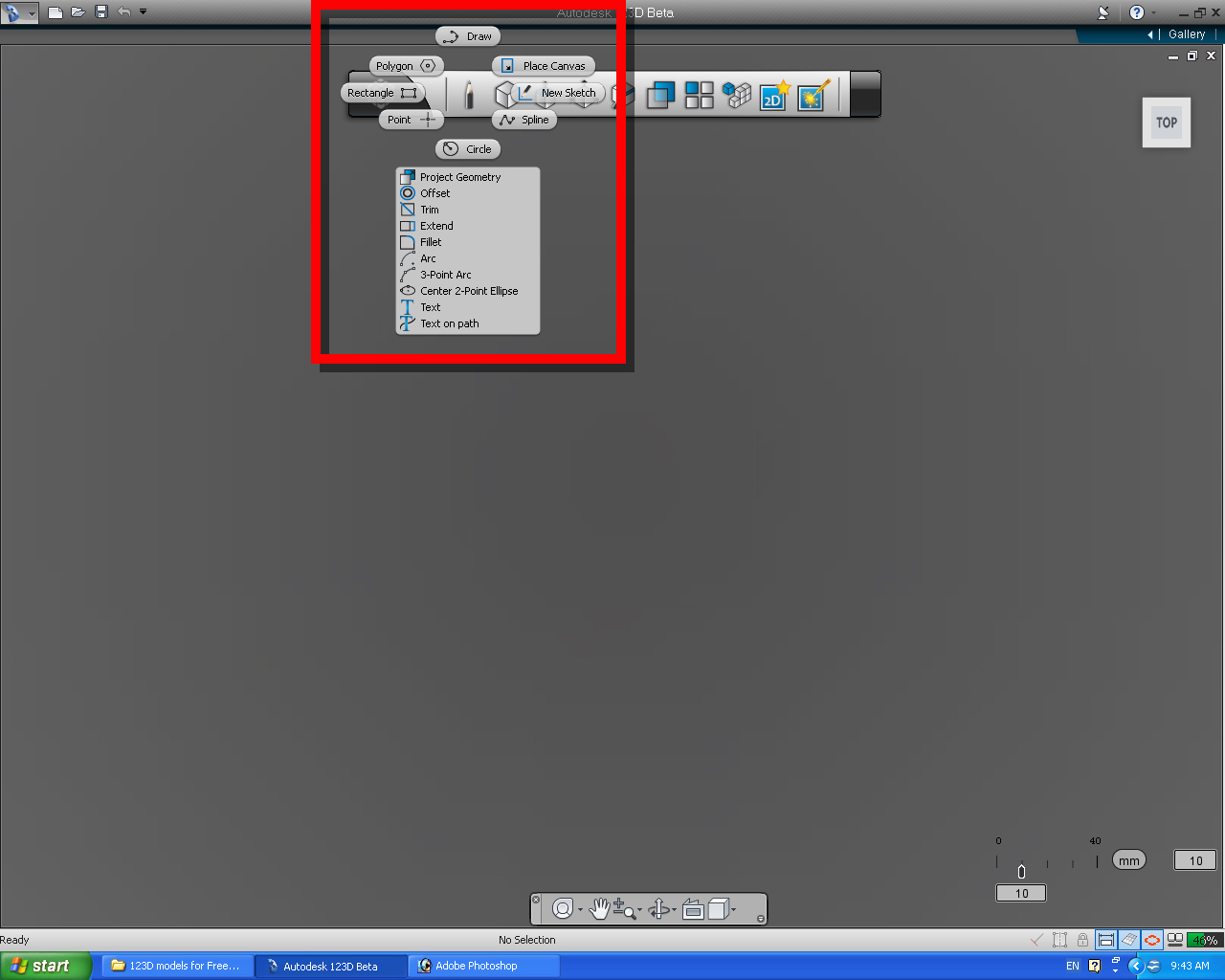
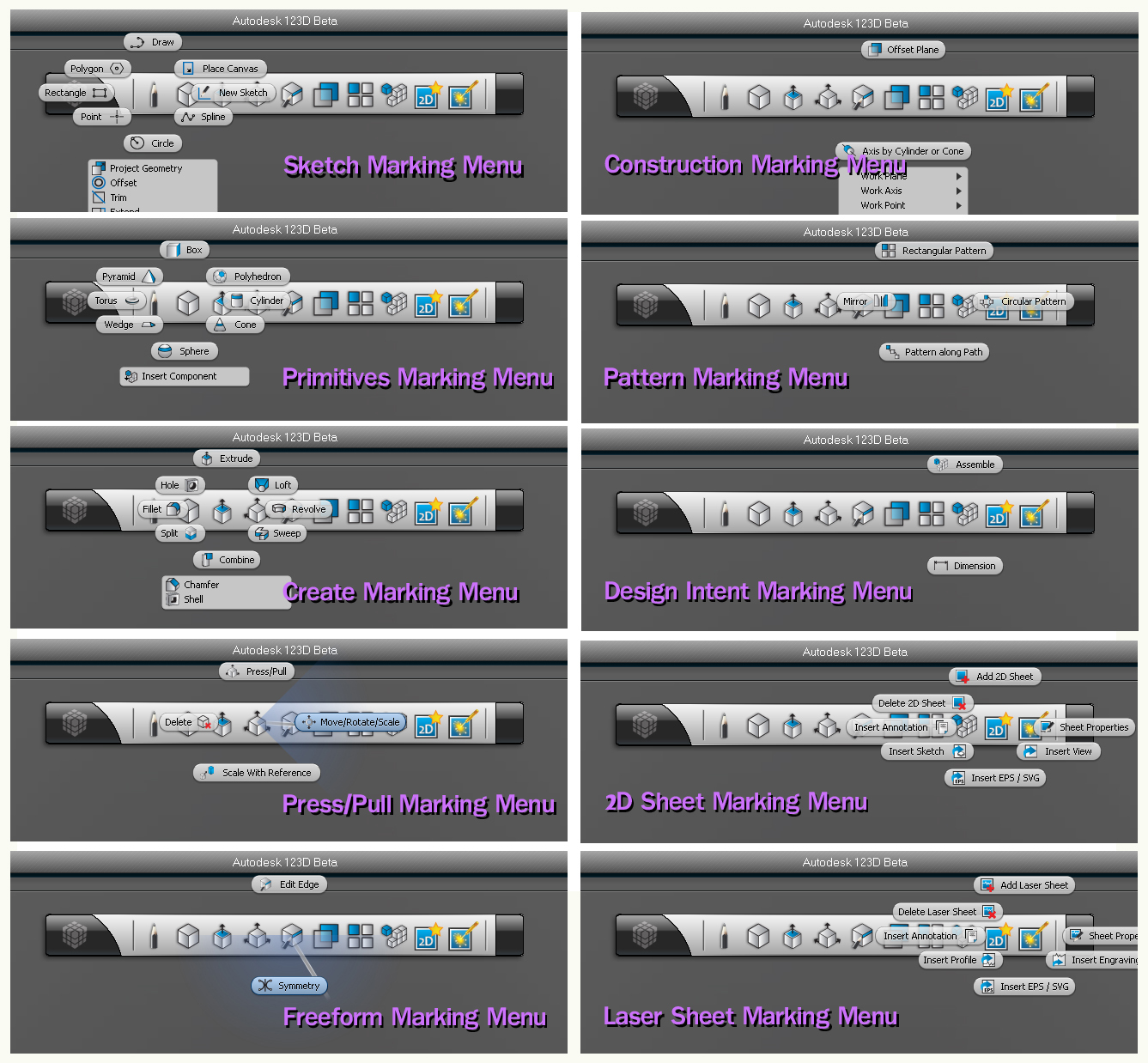
ALL THE MENUS
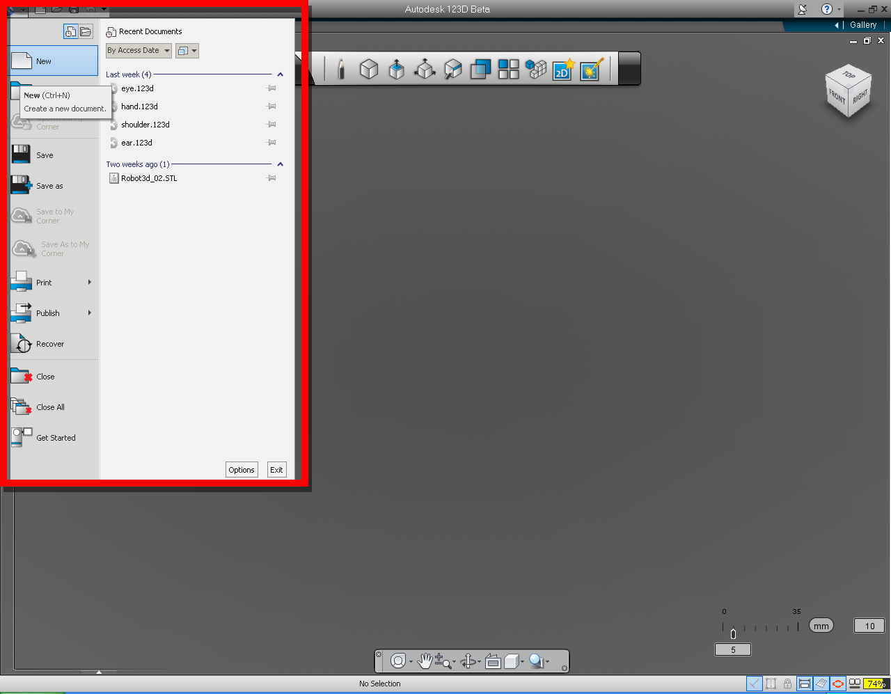
I am going to show you where all the menu are, and what they are called so when I mentioned the name in the following tutorials, we are all know which one to go to and which one to select. See the images below for clarification.
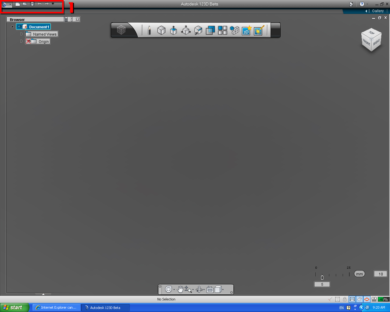
1. Application Menu
Next to the application menu, there is an app. tool bar, with icons that you can select to perform similar task to the app. menu, included redo and undo function.
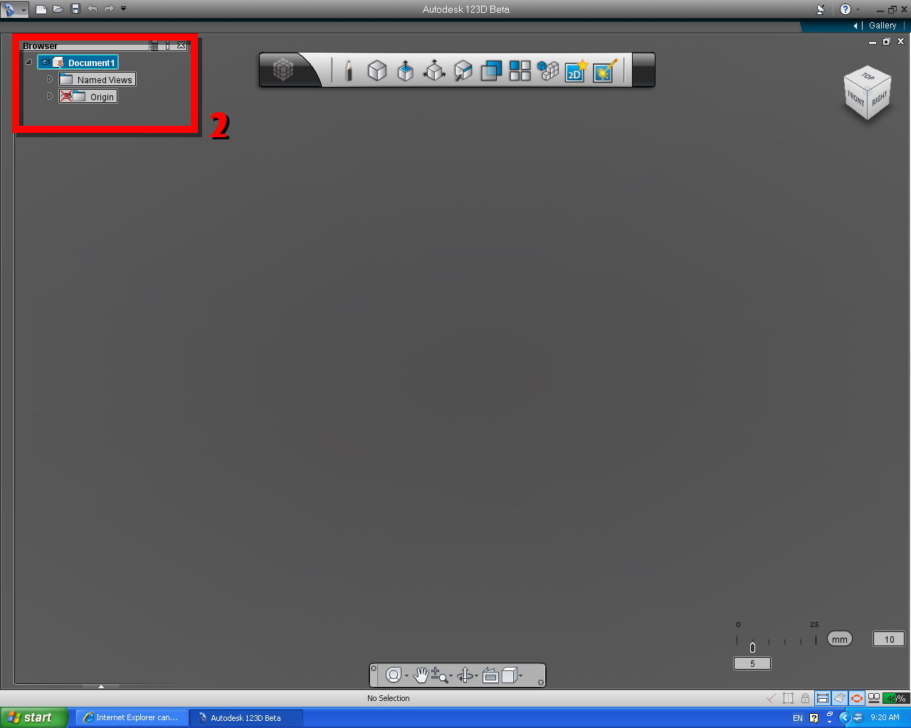
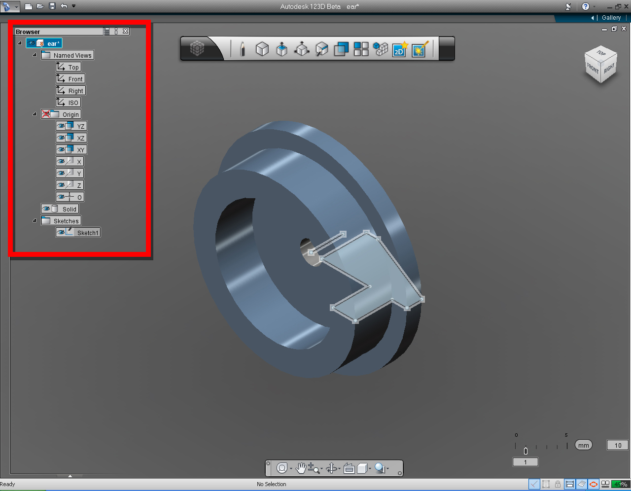
Down the left hand side of the screen is the Feature Browser Menu, it contains the structure of the components of the 2D sketch and 3D model(s). We use this menu to select, deselect, enable or disable (show and hide) the node content of the component.
You can edit the features in the model by clicking on the Node in the Browser.
You can also show and hide the Origin Planes and annotation planes from the Browser and switch between pre-set views.
Clicking the Cross makes the "Feature Browser" DISAPPEAR! To get the Feature browser back by going to Menu > Options > Controls
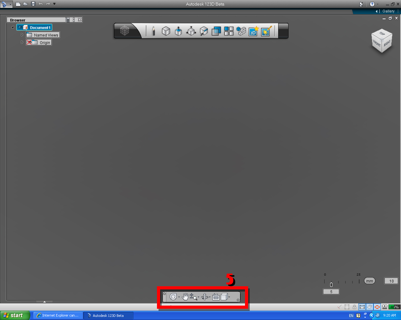
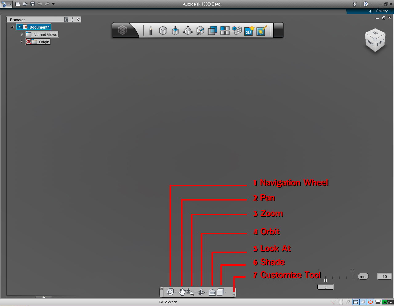
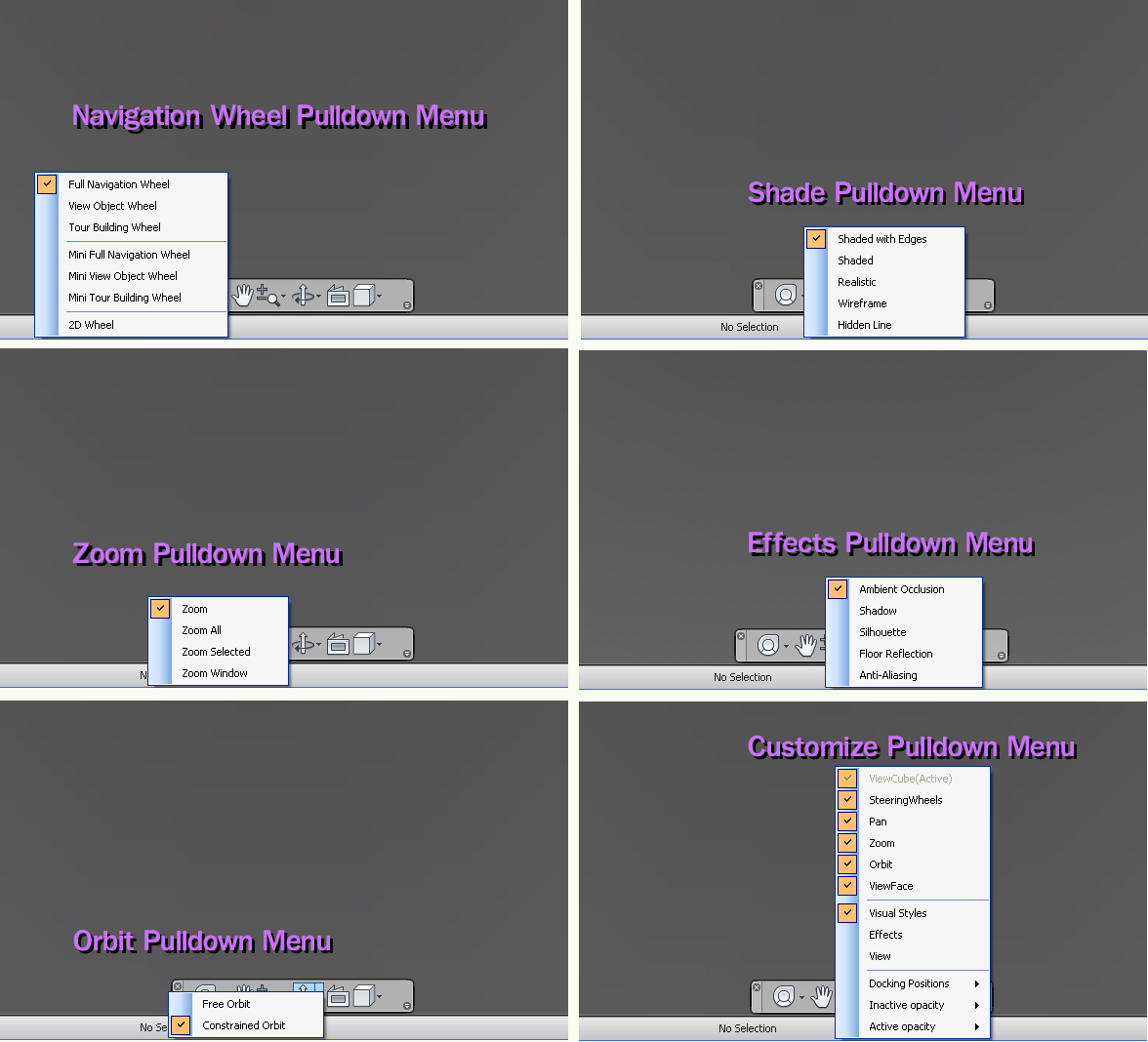
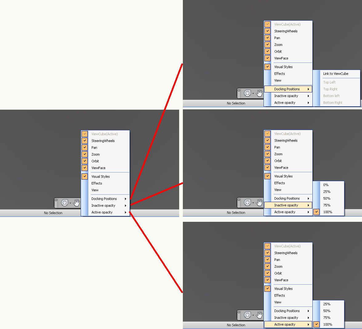
Navigation Wheel, Pan, Zoom Orbit, Look At, Shade, Effects, and Customize tool (small round dark grey circle with little tiny fast forward icon). Navigation Tool Bar located in the middle bottom of the screen.
The status bar also included selectable icons that we can use to set the drawing grid,
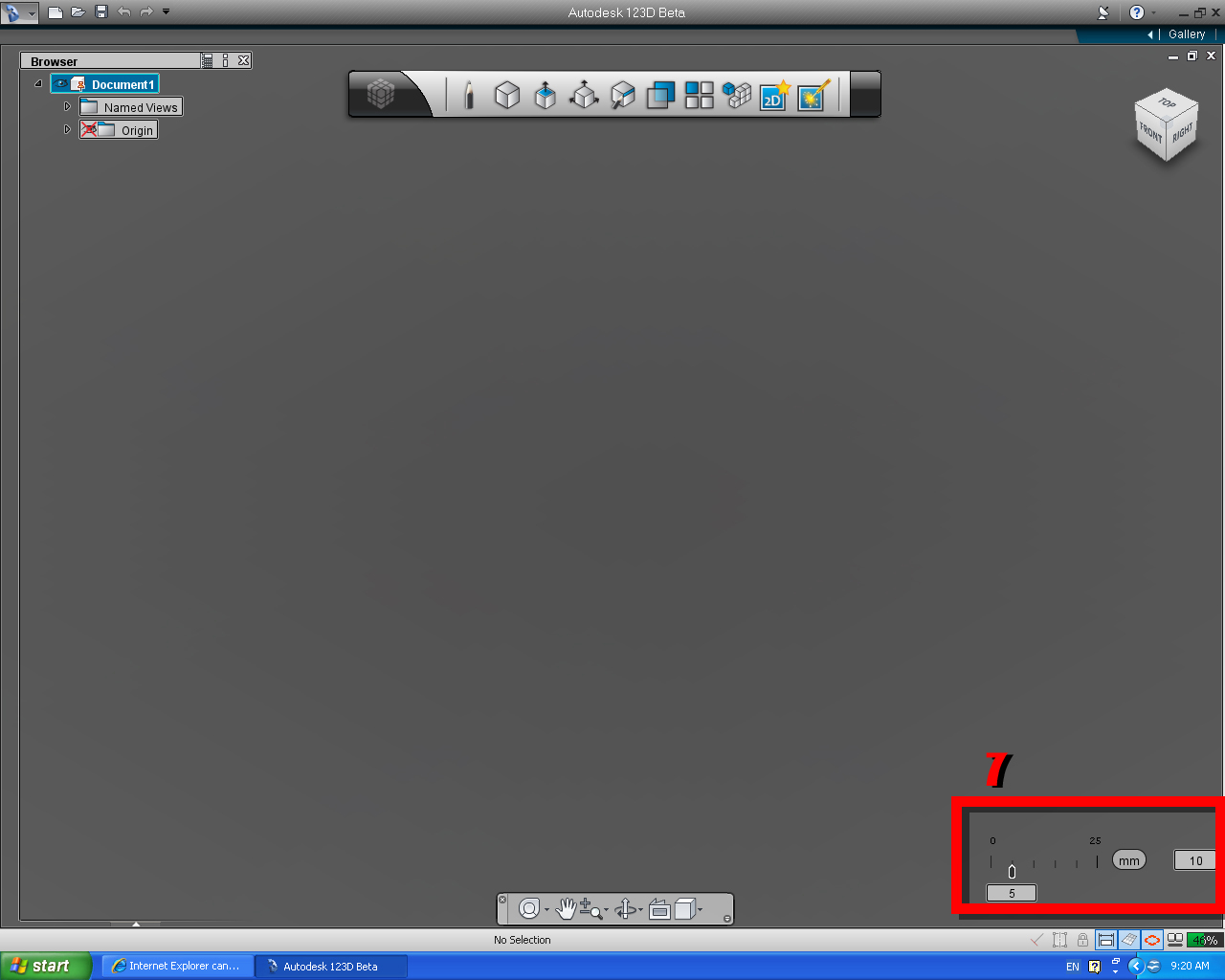
Snap bar is an interface for changing documents units or change scale of the object, or change drawing grid snap value.
The Snap bar helps you set the accuracy of the sketching grid snap and allows you to change units.
This is also where you can toggle the Visibility of Sketch constraints, the sketch grid and Value inputs on and off.
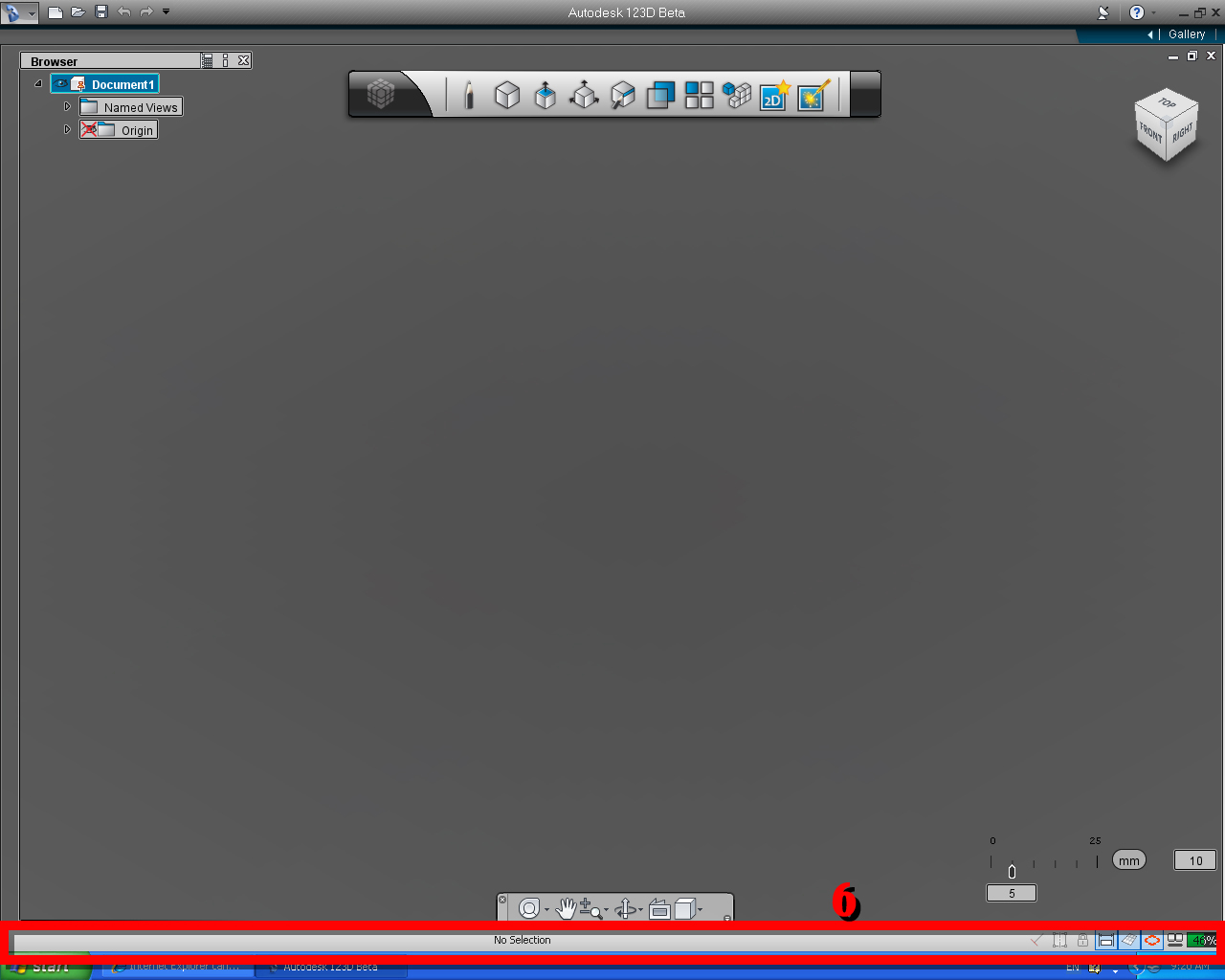
The handy little Gauge in the corner is telling you how much memory you have left.
It is obvious that why it got it name, it has a shape of the pill.
Now that we are familiar with the basic user interface and navigation system of 123D app., let's get start to have fun!
Some words of advice
One way to quickly learn a new application like 123D, is to follow those who did this before or an experts who recorded they knowledges as the video and provided them as the tutorials to others who want to learn.
I provided useful resources with the link in Step 9. It's worth looking at.
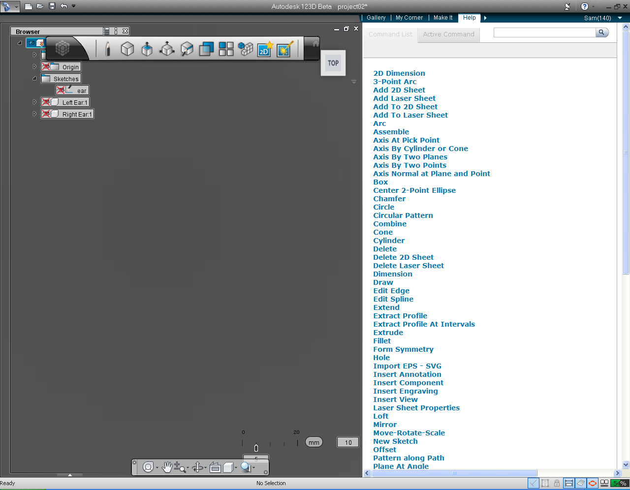
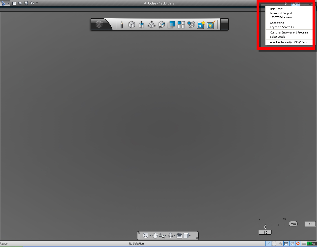
If you are stuck, and need some help, you can use the help icon (?), located on the top right hand in the 123D app. to find some solution. If you still could not find any answer, you can visit 123D Forum, or Group such as 123D Group at Instructables and post your question.
Note: There are so many different way to create exactly the same object. We can draw the lines in different directions. We could use different commands or functions to create an object with end result being the same, for example if we were to create ears model, we could use "Copy" function, and then "Rotate" the copied ear to make right ear. As you are going along and try to create something of your own you will find too many ways to create exactly the same object.
So the more you learn, the more you know how to be efficient way to create 3D model. And it is fun to find a new way!
Setup and Practice...
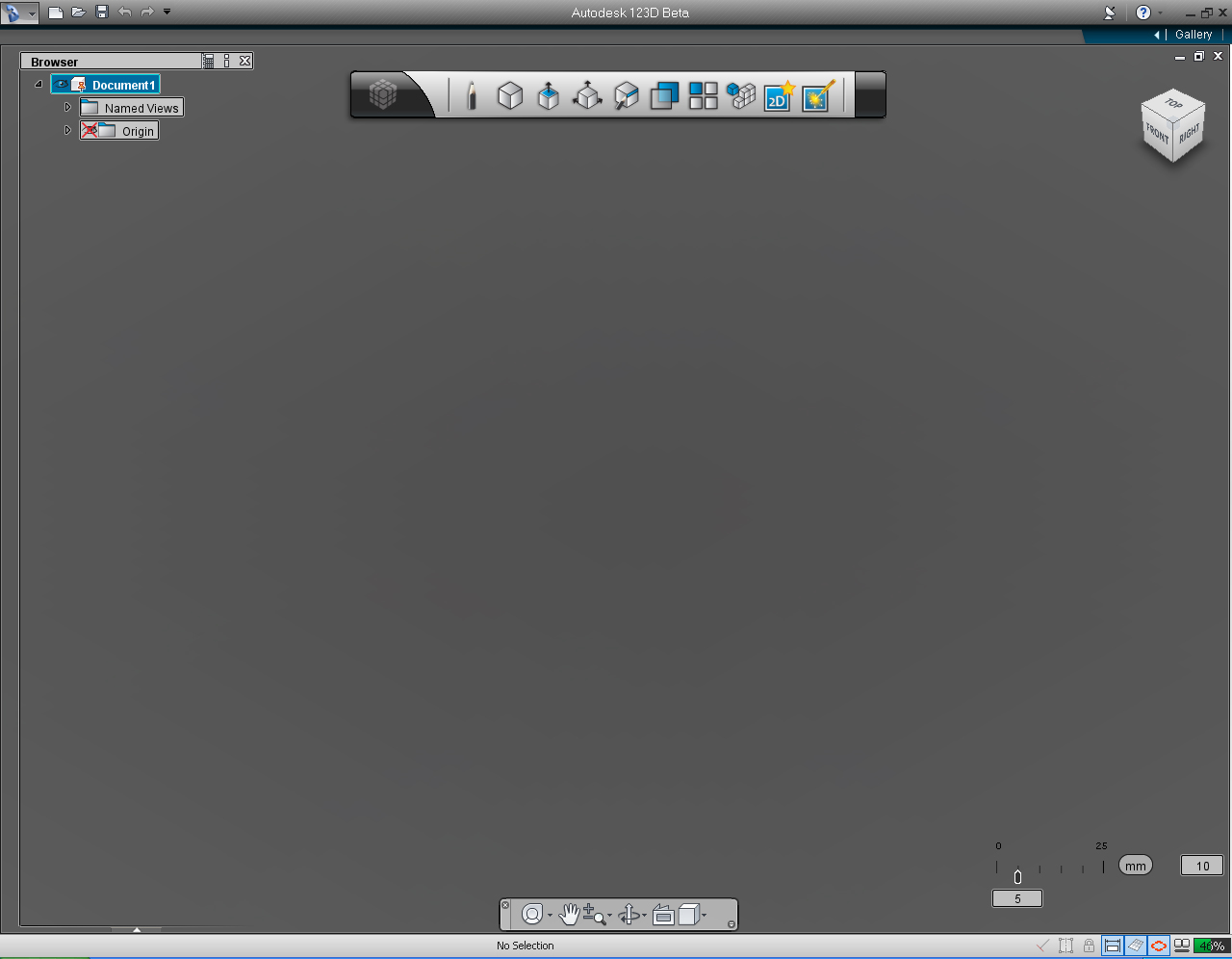
After we learned about the UI (User Interface) and Navigation systems of 123D app. We are going to practice a little bit before going into the real stuffs.
Let's open 123D app., if you are not already. After we got the 123D ready.
First Exercise: Drawing Setup
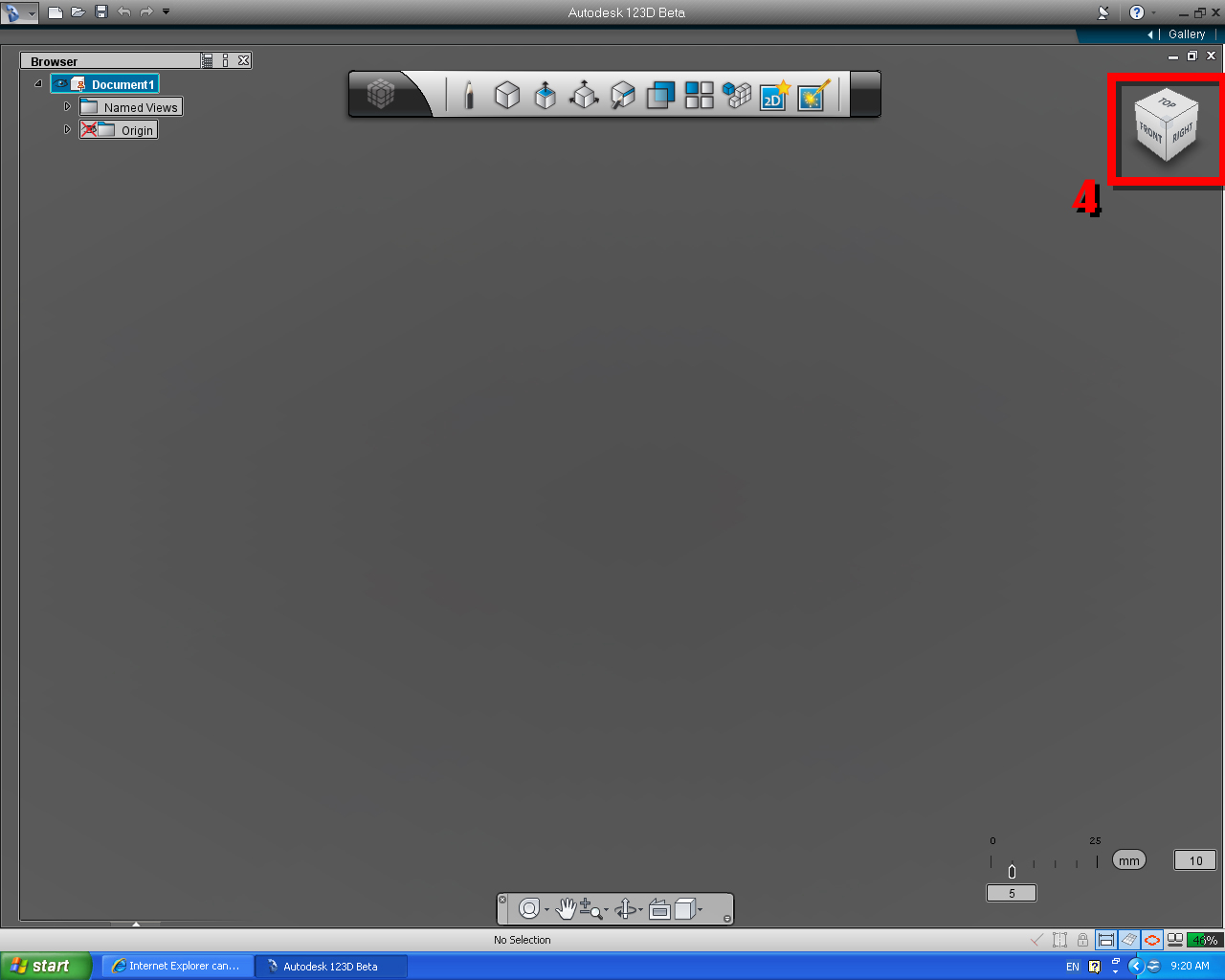
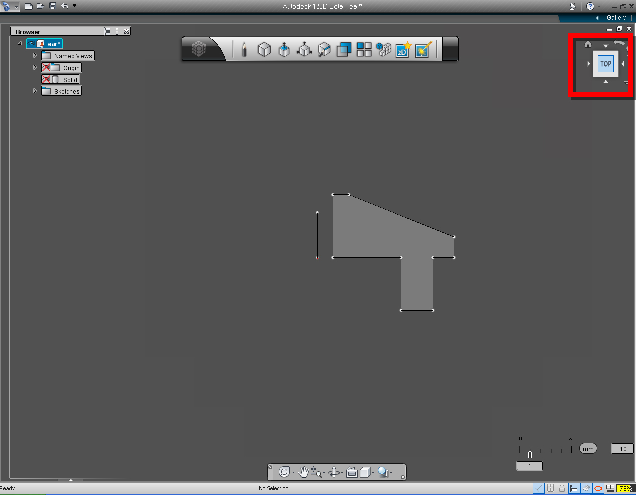
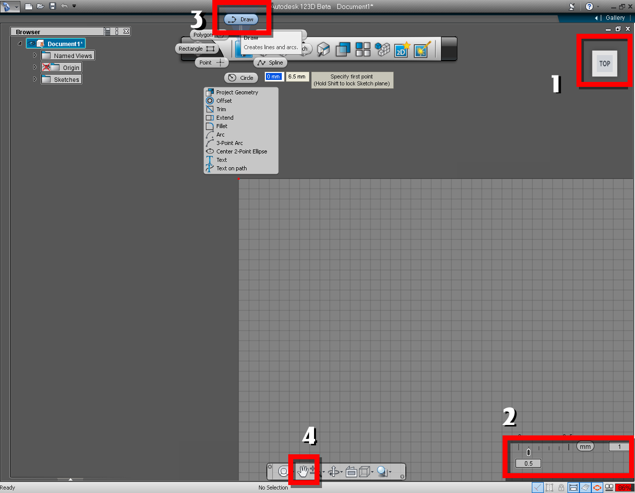
1. Use the "View Cube" to set our drawing plane to TOP plane.
Move mouse over the TOP plane of the "View Cube" until the top view cube got highlight in blue. Click or drag left mouse button to control the "View Cube"
2. Setting the grid interval and snap value.
Move the mouse to "Snap Bar" menu (at the lower right hand corner of the screen) Check if the unit if in mm. (Milimeter), if not change it, by move the mouse over the unit, the selection list will appear move the mouse over the mm and click to confirm.
Next, we will set the grid spacing. The grid spacing is the value shown in the rectangle on the right hand side next to the unit we just set. Let set the grid interval value to 10. The grid Interval will be displayed as the dark grey color on the sketch plane.
Then we are going to set the grid unit. The grid unit is shown in the rectangle underneath the "Snap Bar". We will change the value by move the mouse over it, the existing grid unit will be highlighted, type in the value of 0.5.
We are done with the setting of the grid interval, grid unit and the sketch plane. Let go ahead and save
3. Access the draw function
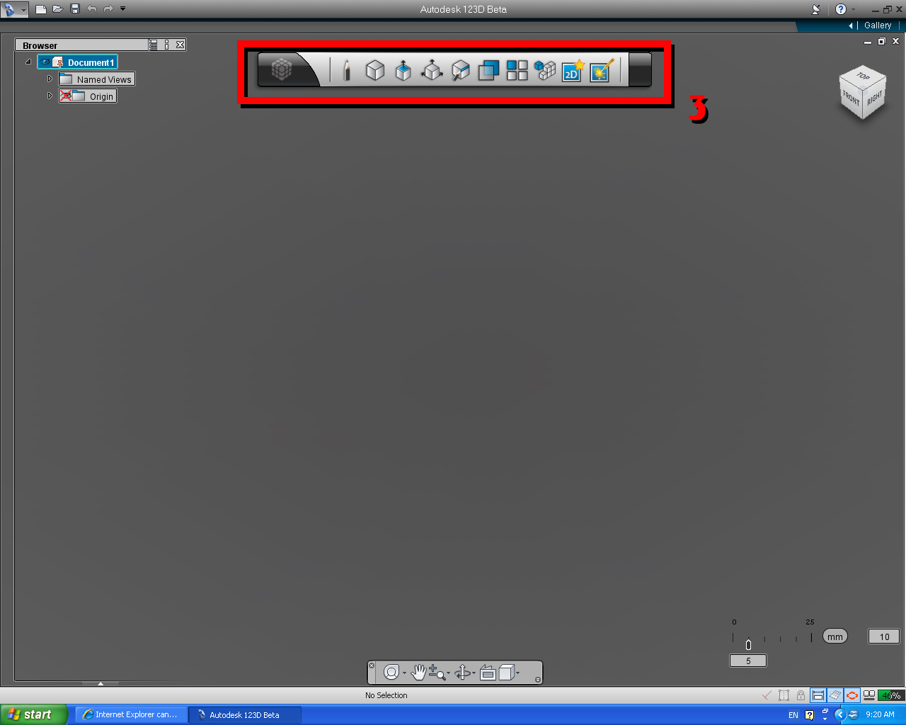
Click at the pencil icon on the "Main Tool Bar", and select "Draw" from the Draw's "Marking Menu".
Move the mouse into the displayed grid drawing plane, use the mouse scroller, to scale the grid drawing plane to be bigger (easier to draw). Let say, scale the plane up until two or three grid interval fit on the screen.
4. Adjust the drawing plane.
Use the "Pan Tool" (Hand icon) on the "Navigation Bar", to move the Origin point (red dot on the top left corner of the drawing plane) to be in the middle of the screen. (as shown in the image no. 2)
You can save the file as the template for later use. Since we are going to use the same setting throughout the project. Give the name to be something appropriate. The file will be saved as 123D file format (*.123d)
Notice that when you move the cursor over the drawing plane before starting to draw the first line, there is a message box remind you to "Specify the first point on the drawing plane and Hold down the Shift Key on the keyboard to lock the sketch plane".
123D app. want to make sure that you are drawing on the right plane. Especially when, we are starting to draw from the orignal grid line, which have three possible plane to be draw on. (Change the View Cube to home, you will see, there are six drawing planes available to draw on, as in the six surface of View Cube)
Second Exercise: Draw 3"x3"x3"
Following is the conversion
1" = 2.54 cm
10 mm = 1 cm
25.4 mm = 1"
Since we also want to have all of the 3D models above to fit within 3x3x3" cube.
Instead of figuring out ahead of time, for the value of 3x3x3" is equal to 76.2x76.2x76.2mm. 123D allows us to enter the formula directly into the input box and it will calculate the result for us.
- "Box" pill from "Primitive" Marking Menu (or bucket).
- "Create" tool in Main Tool Bar.
- "Revolve" function in the Marking Menu to create the 3D model of an ear.
- "Copy" solid model of an ear to new component "Left Ear"
- "Join" both ears together as a single object.
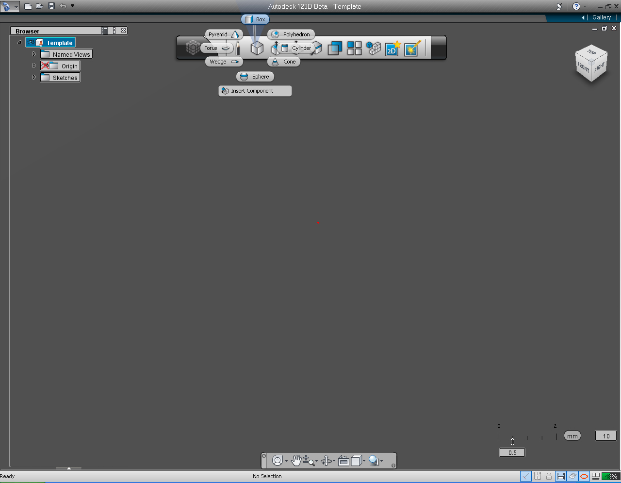
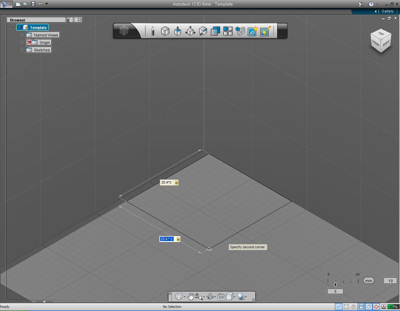
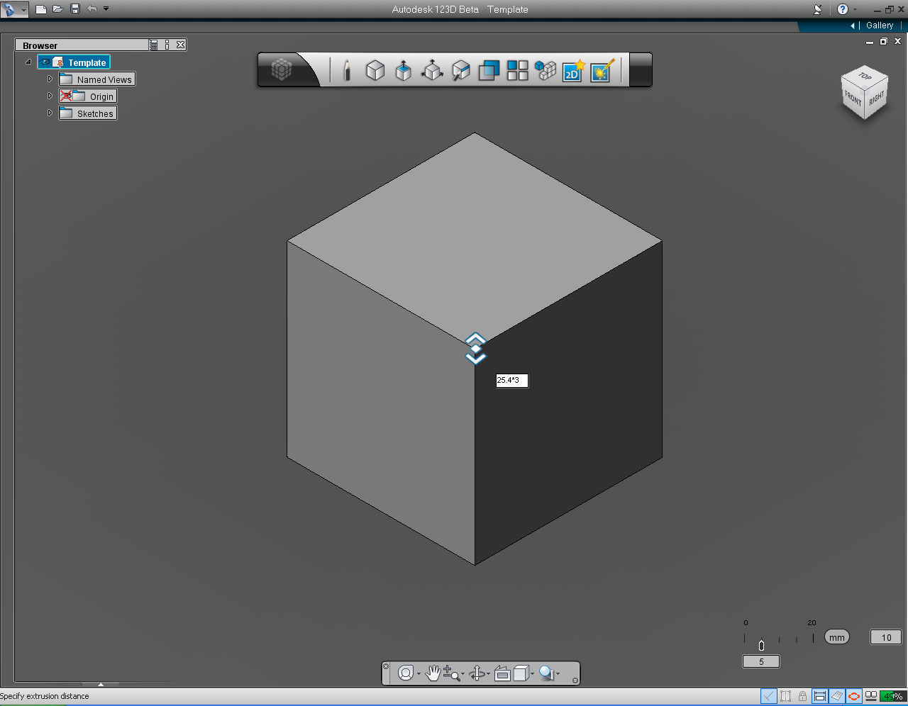
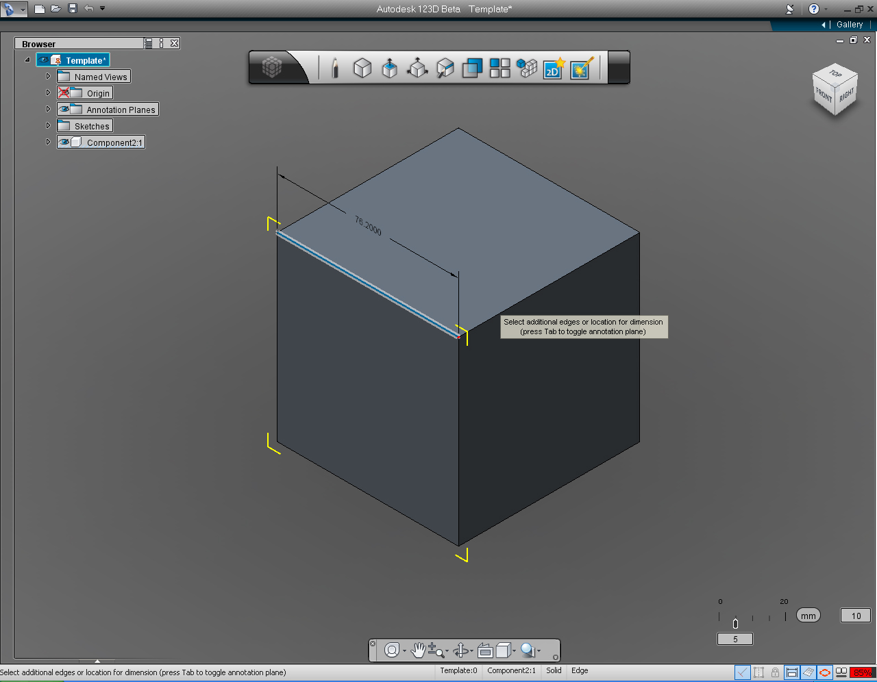
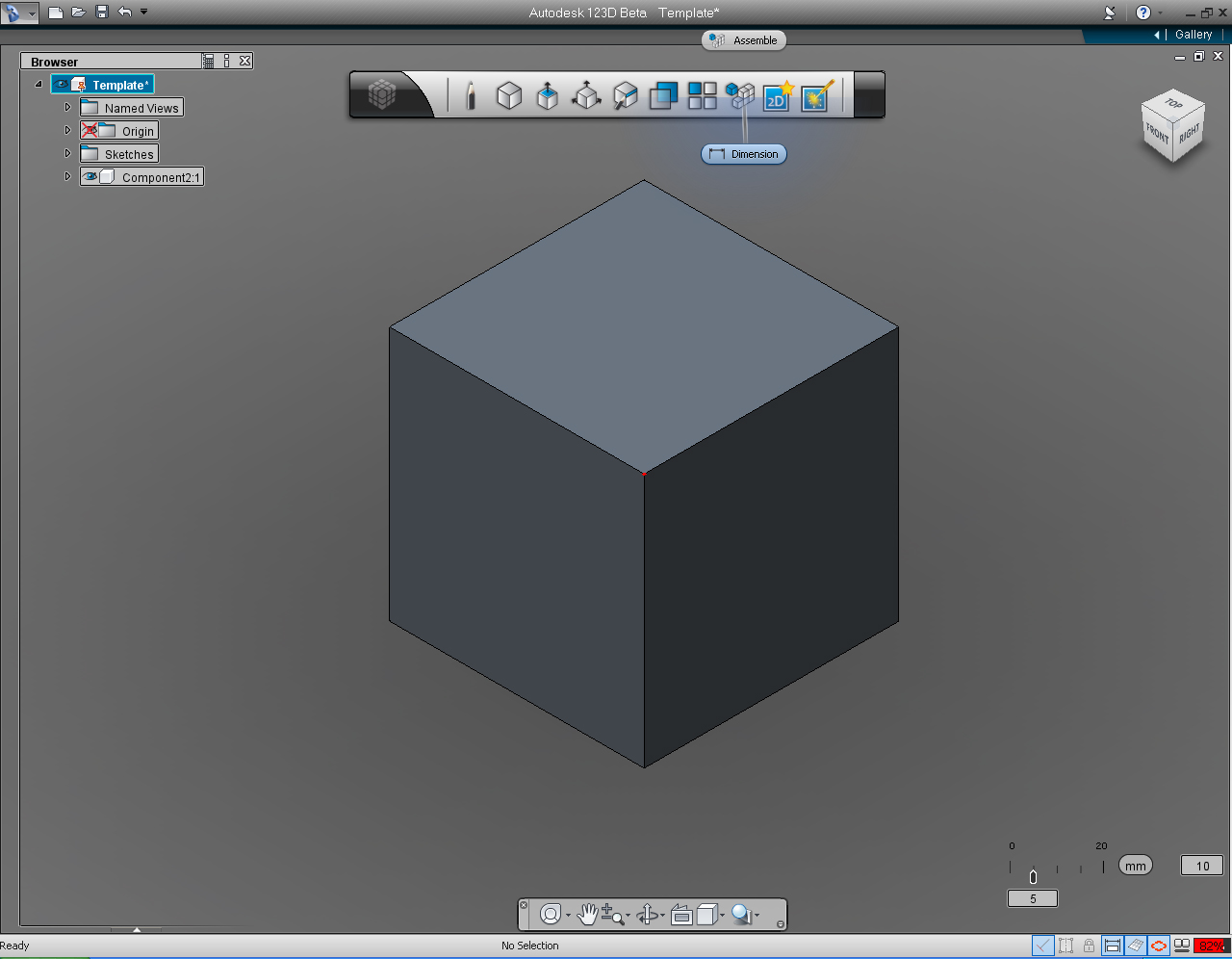
To create 3x3x3" cube with the formula input method, follow the instructions from image# 3 to the last image in this step.
1. Select Primitive Menu, and click at "Box" pill in the Marking Menu.
2. Specified the width and length, by type in the formula 25.4 * 3 in the input box on both sides, as shown.
3. Type in 25.4 * 3 into the input box, when 123D ask you to specify the height of the cube.
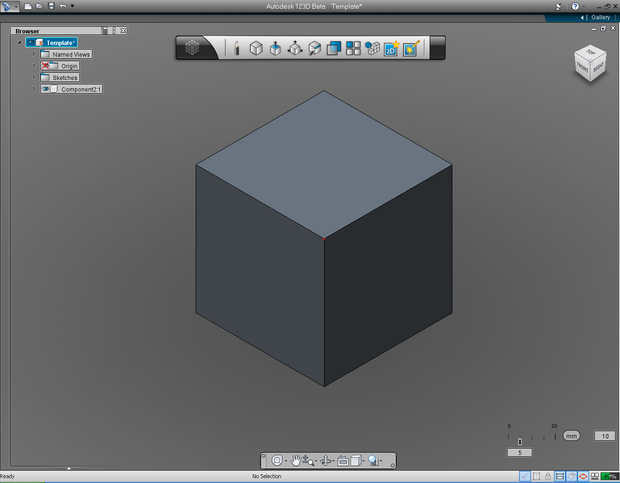
4. This is the 76.2x76.2x76.2mm. cube. Next, we are going to check if the dimension are corrected.
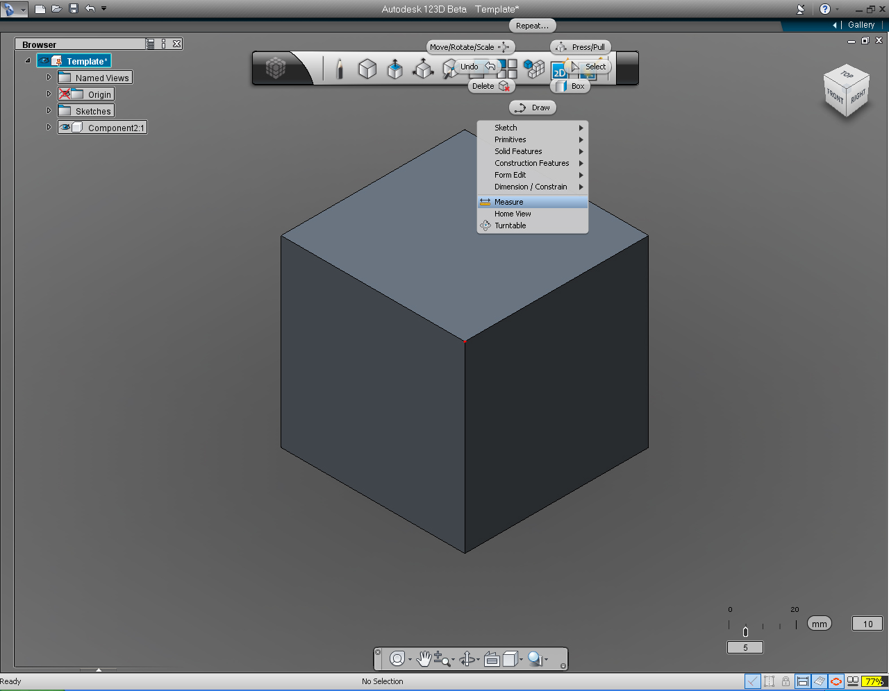
5. Select "Design Intent" Marking Menu on the Main Tool Bar. Then select "Measure" from the drop down list.
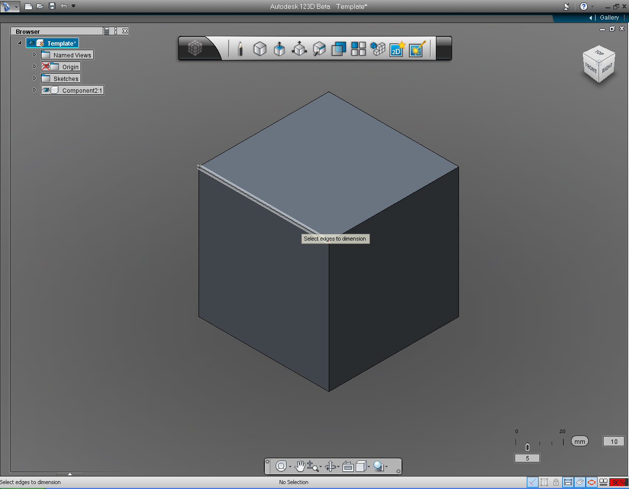
6. Select an edge of the cube.
7. The dimension line with the dimension of the selected edge (76.2000) show up. And we got the right dimension!
8. Re-select the "Design Intend" menu on the Main Tool Bar. Then select "Dimension" pill.
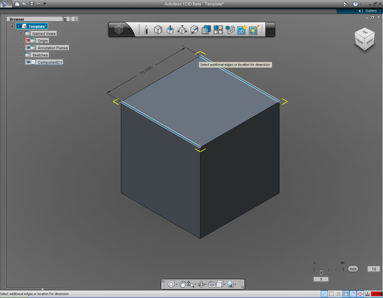
9. Select two opposite edges on top of the cube. The displayed dimension show 76.2000. Again, we got the right dimension!
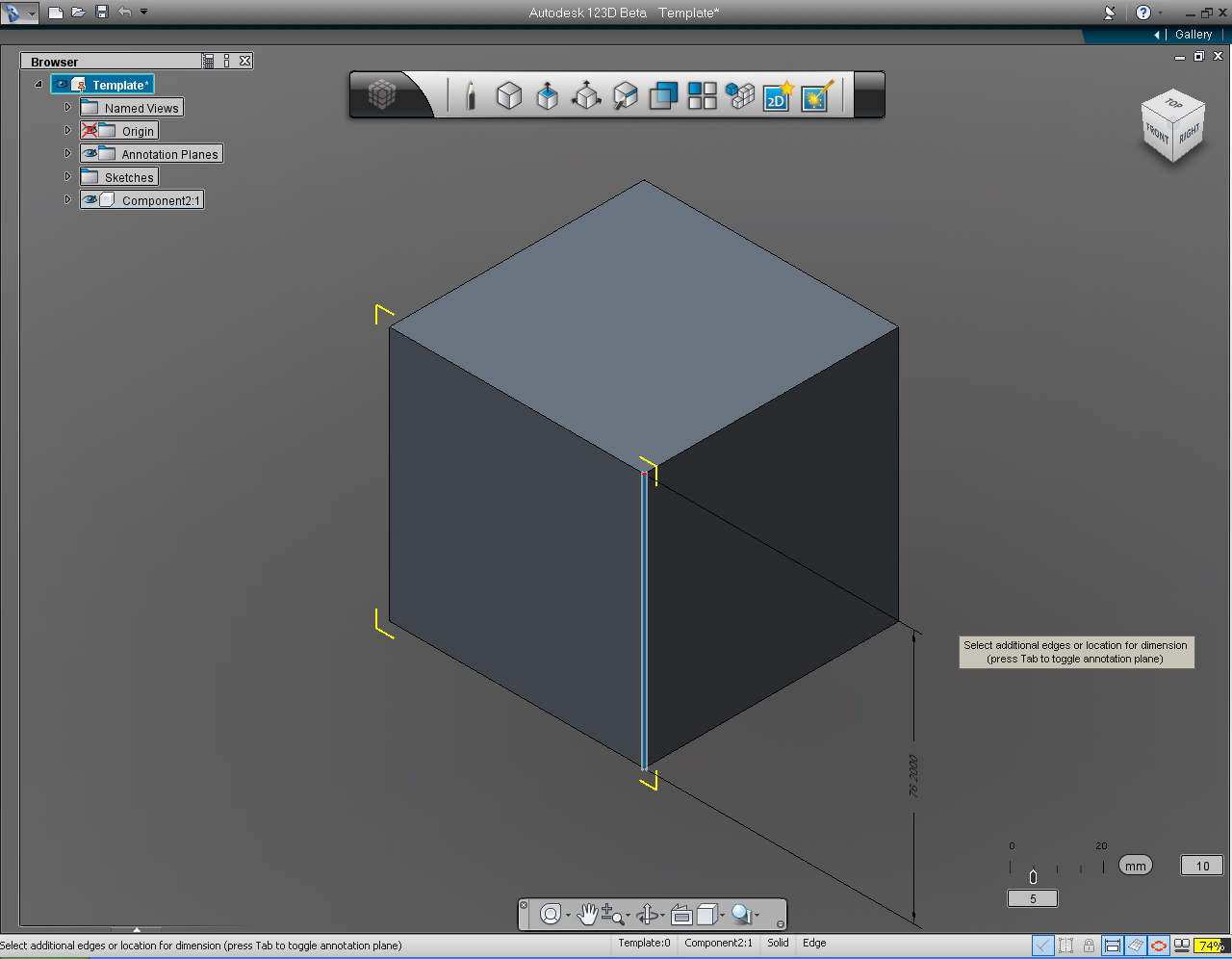
10. Repeat the command, and measure the height of the cube. And the dimension appears with the same value(76.2000). We got the 3x3x3" cube!
Further Study:
Autodesk 123D - Intro to Sketches Video Series: Precise Sketching
123D Tips Video Series: Tip#2: Modeling Starting from a Sketch
Create Ears


Below are the list of the commands we will be using:
- "View Cube"
- "Draw" function in "Sketch" Marking Menu (or Bucket)
- "Revolve" function in the"Create" Marking Menu to create the 3D model of an ear.
1. Rendering of the ear 3D model that we are creating.
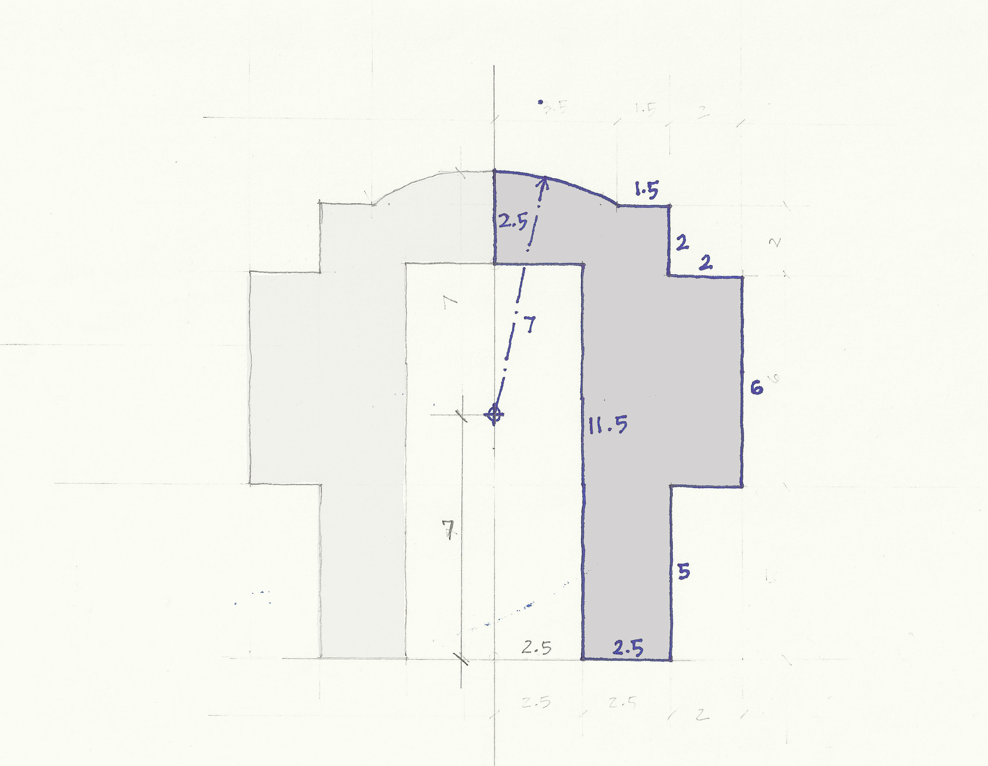
2. Cross-section or profile of the eye, with dimension to be drawn in 123D
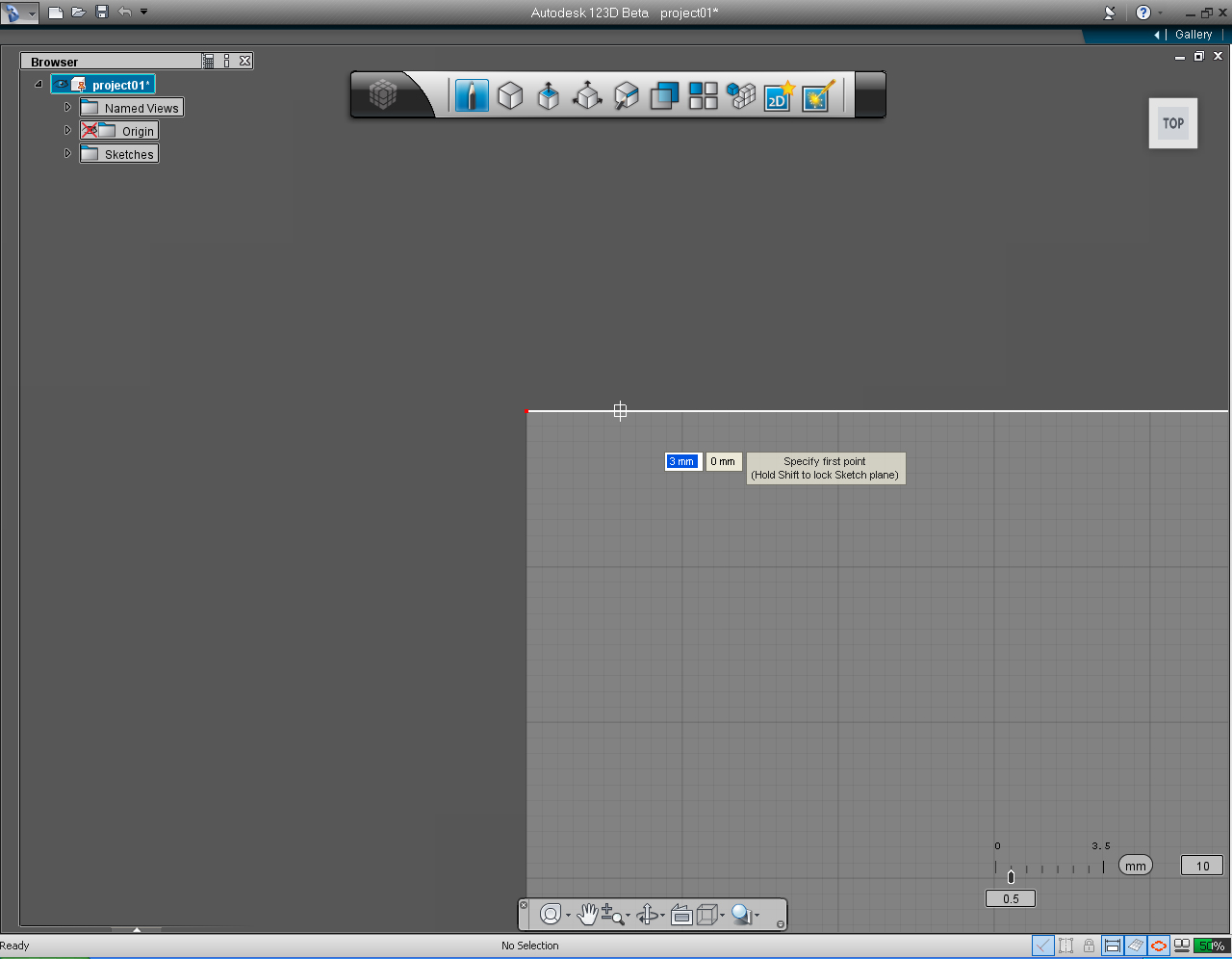
3. Specify the first point at the profile at coordinate (3, 0), by typing the values with keyboard or drag the cursor to coordinate (3, 0) and click the left mouse to confirm.
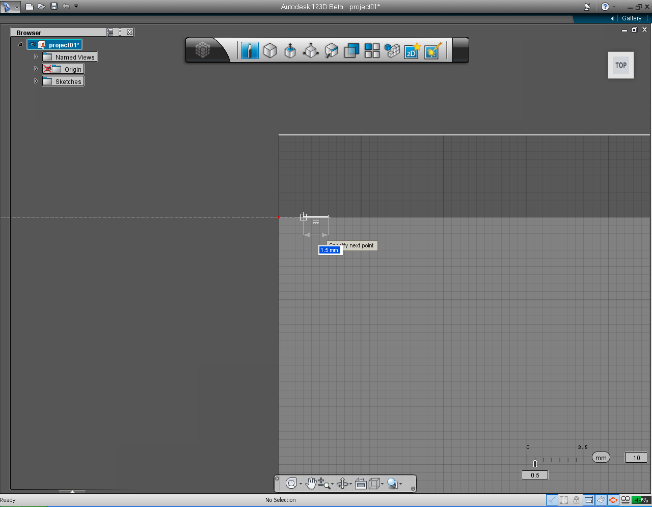
4. Drag the cursor to the left until we get the value 1.5 display in the input data box, or type in the value 1.5 using the keyboard.
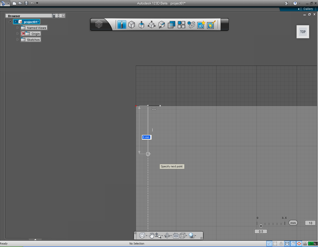
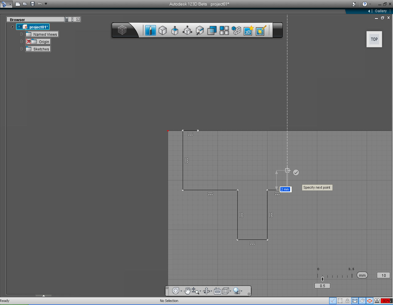
5. Drag the cursor downward until you get 6mm length to draw the next segment.
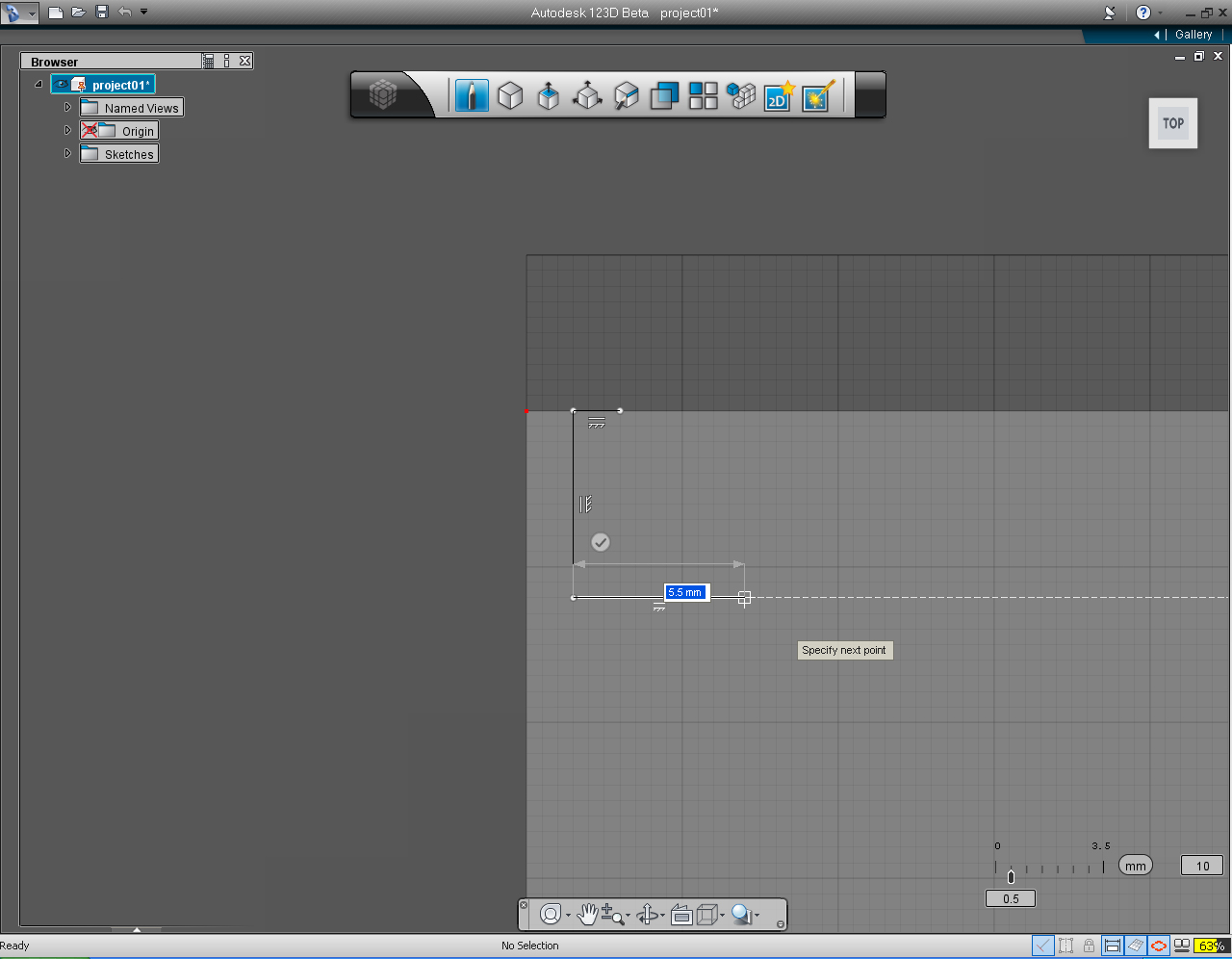
6. Continue drawing the line to the right perpendicular to the previous line until we get the dimension of 5.5mm.
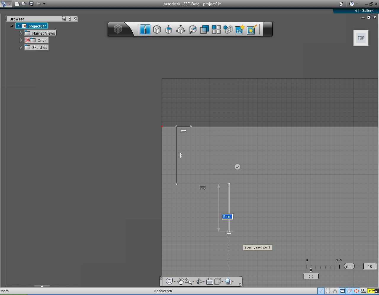
7. Drag the line down to get the distance of 5mm. Then click left mouse button to confirm.
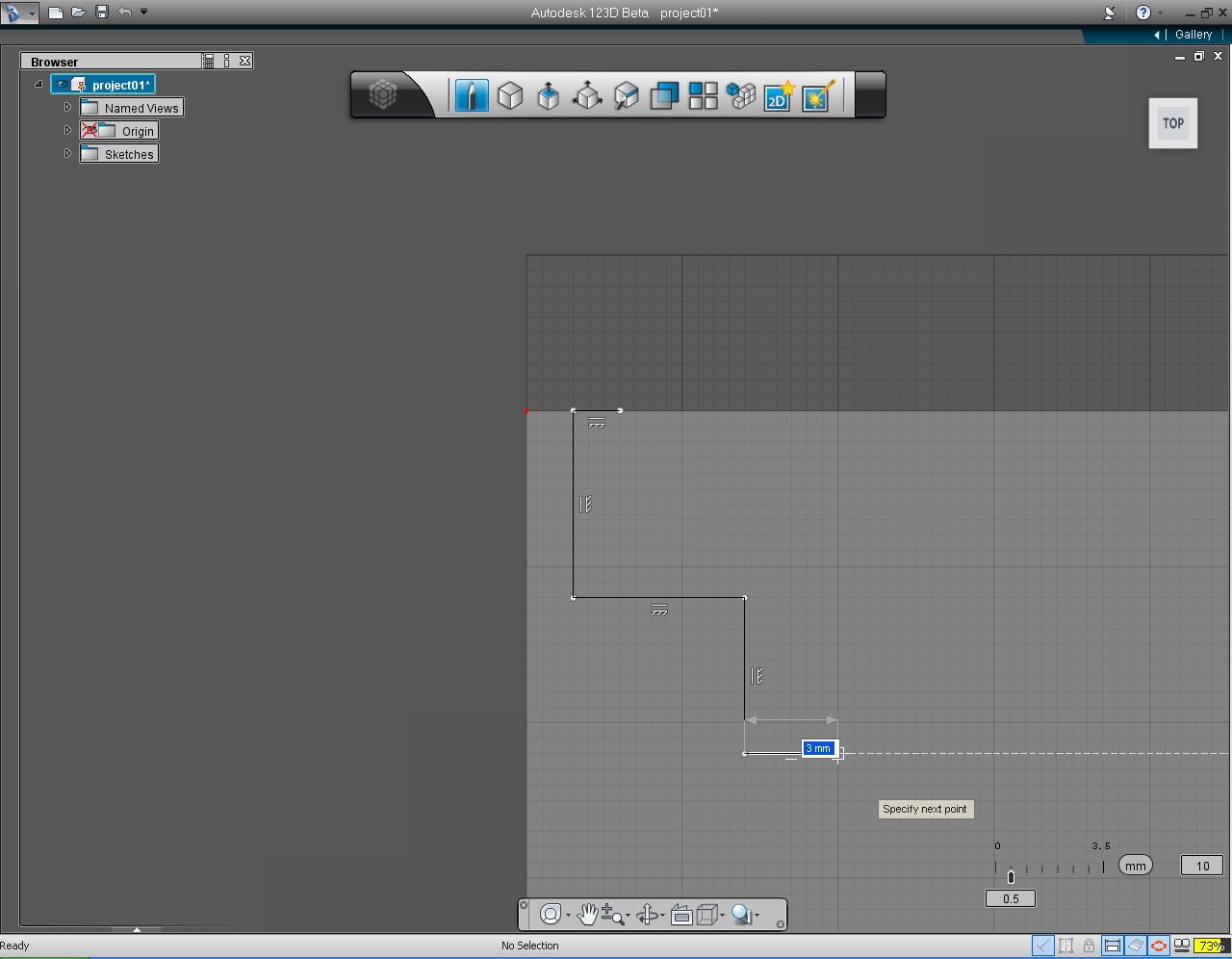
8. Continue to draw the perpendicular line to the previous line to the right with the dimension of 3mm. Click the left mouse to confirm.
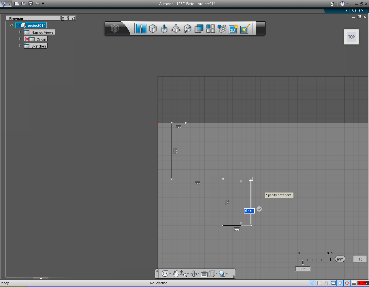
9. Draw the next line in the upward direction, perpendicular to the previous line, to the dimension of 5mm. Click left mouse button to confirm.
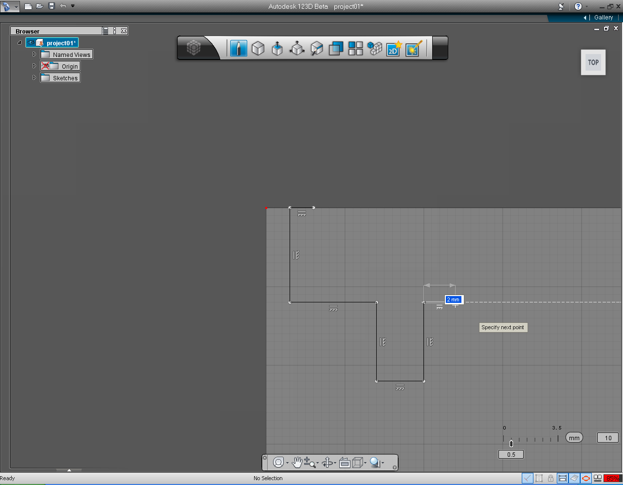
10. Draw perpendicular line to the previous line toward the right to the length of 2mm. Click left mouse button to confirm.
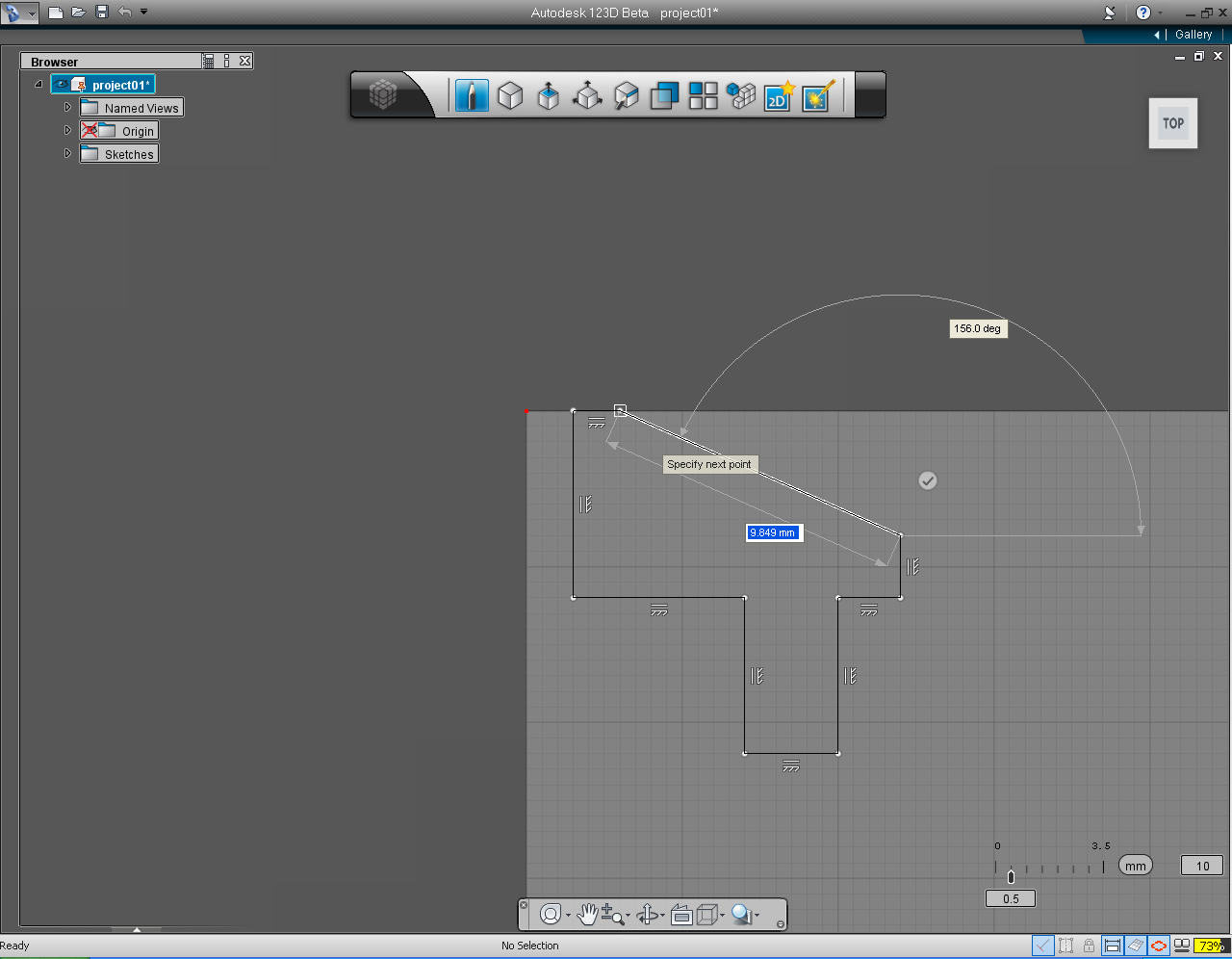
11. Draw another perpendicular line upward to the length of 2mm. Click the left mouse to confirm.
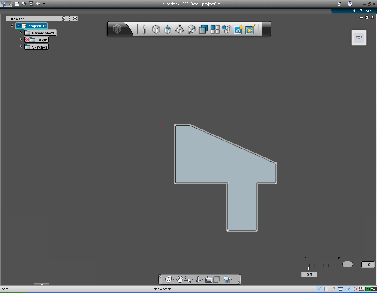
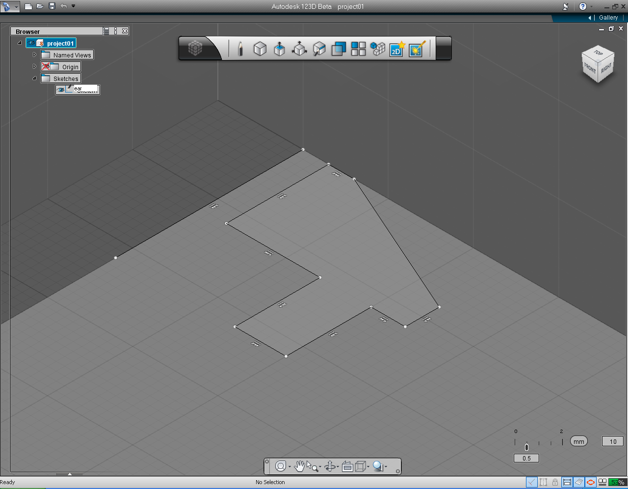
12. Connect the line from the last end point to the very first point of the profile. Click left mouse cursor to confirm.
13. Now, we got the final profile of the ear. And we are ready to make this flat profile into 3D model!
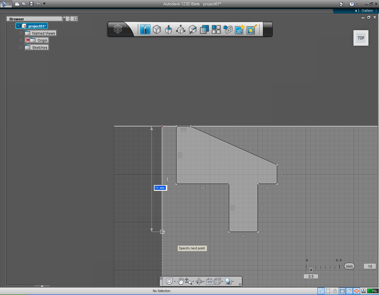
Before "Revolve" this profile into 3D model. We need one more reference, a line for the profile to "Revolve" around to make 3D ear.
14. Select "Draw" pill in the "Sketch" Marking Menu. Pick origin point - the red dot, (0, 0), then draw a line downward (align to the grid line) to any length.
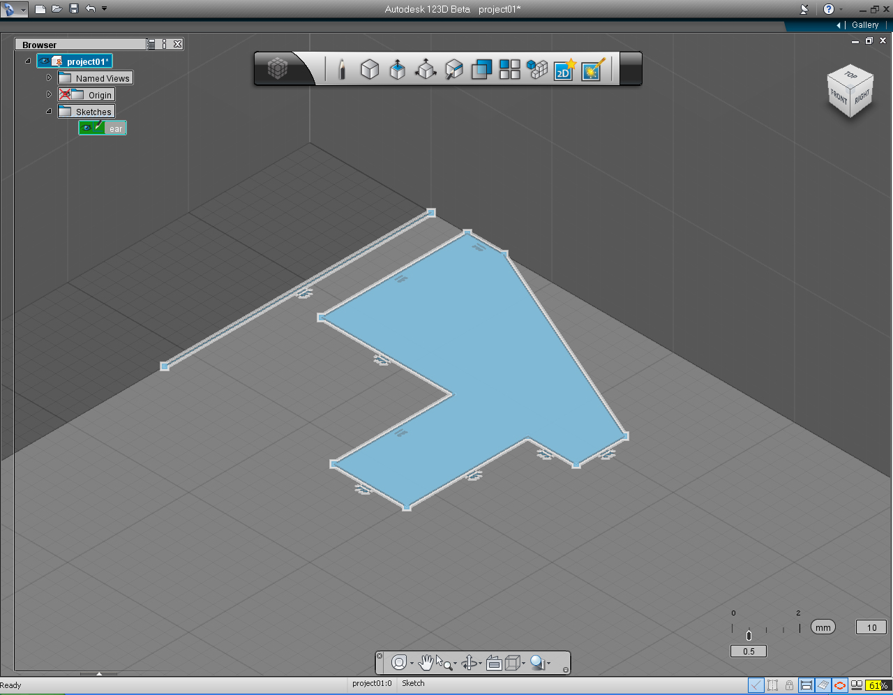
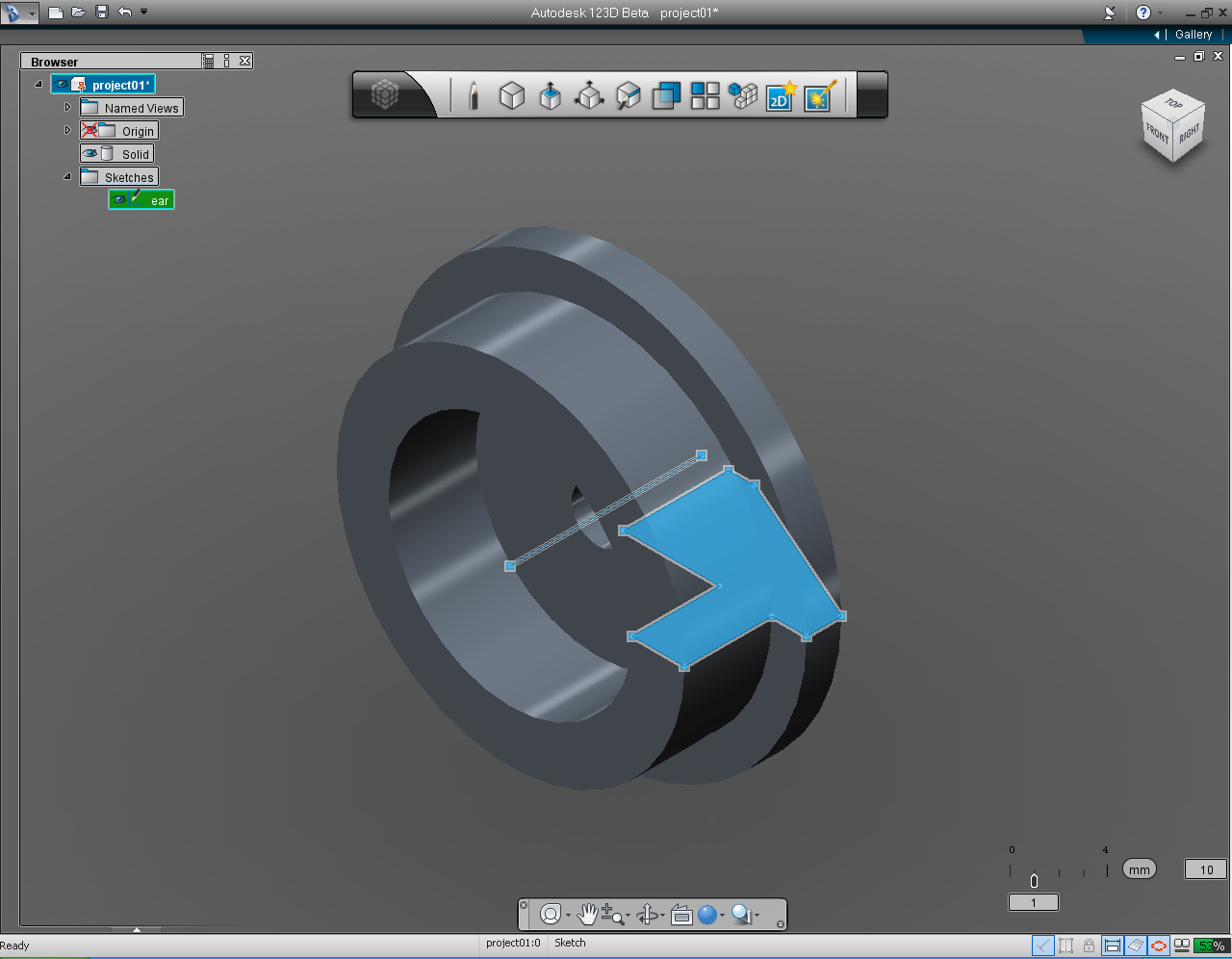
15. Since we now have the complete ear profile. We could change the name of the sketch to "ear". Expand the Sketches Folder, by click at the black triangle in front of Sketch Folder. Highlight the name "sketch1" and rename it to "ear".
16. After rename the sketch to "ear", left click at "ear" sketch to select the profile.
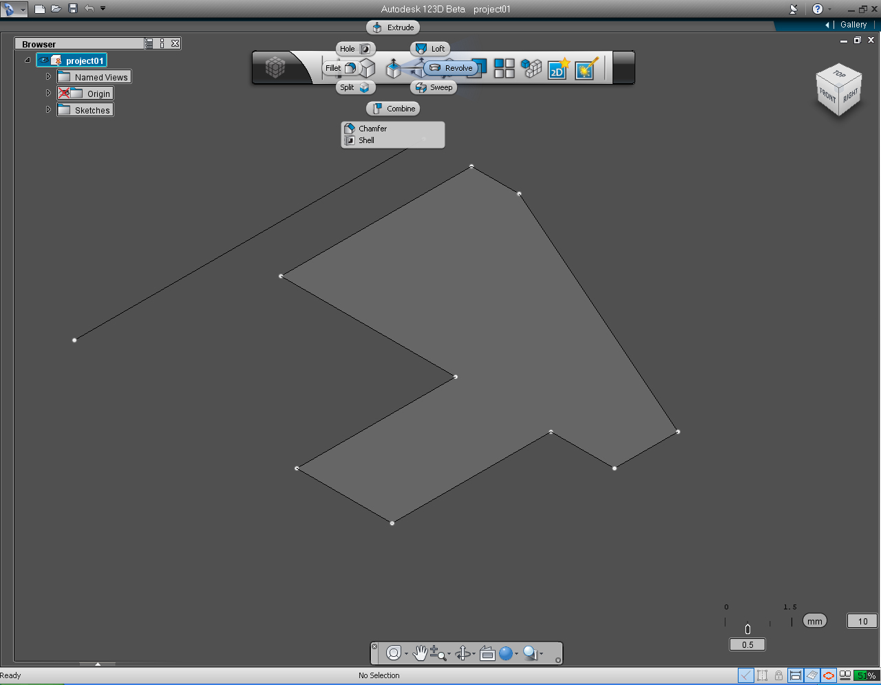
17. Select "Revolve" pill in the "Create" Marking Menu.
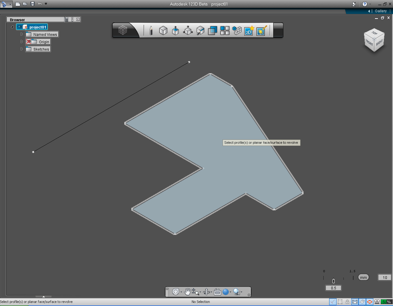
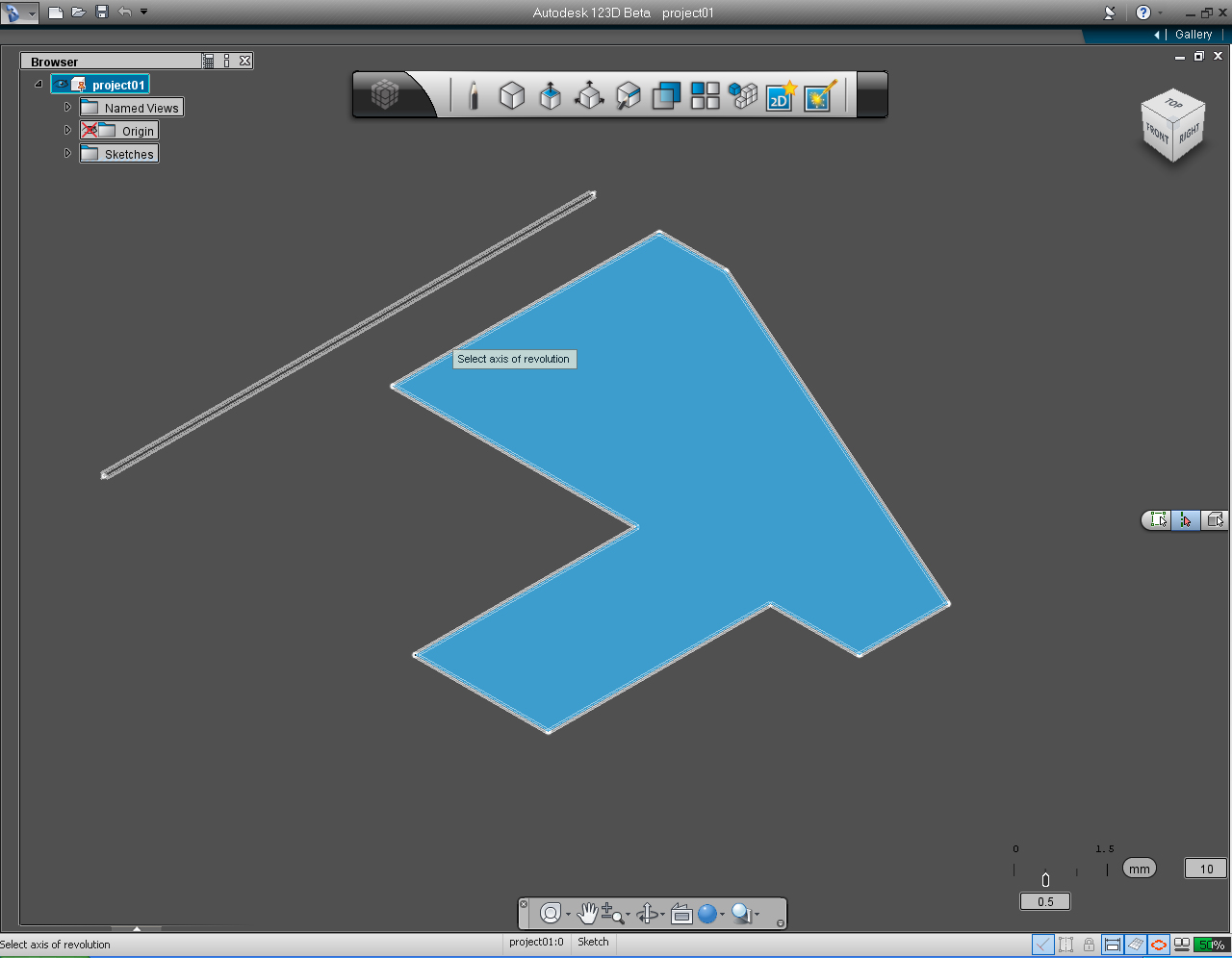
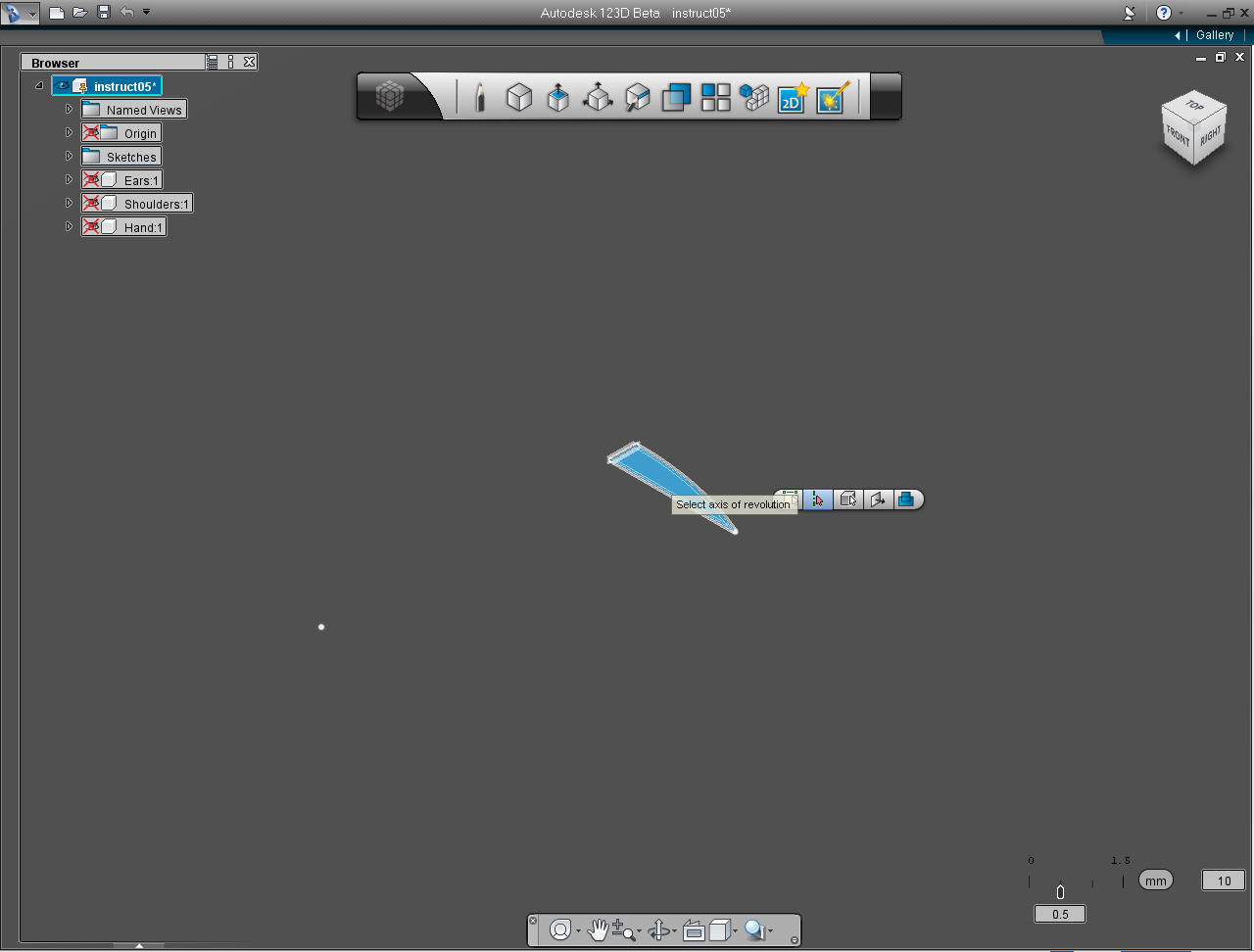
18. 123D will ask you to select the profile(s) or planar face/surface to revolve. Click the "ear" profile to select.
19. Again 123D will ask you to select the axis of revolution. So, pick the individual line as an axis of revolution.
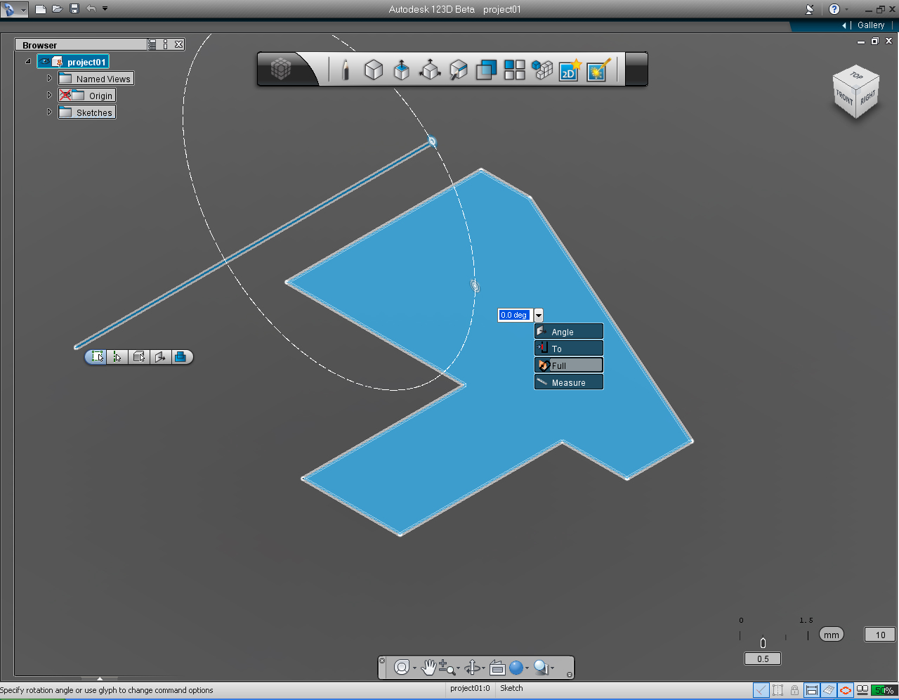
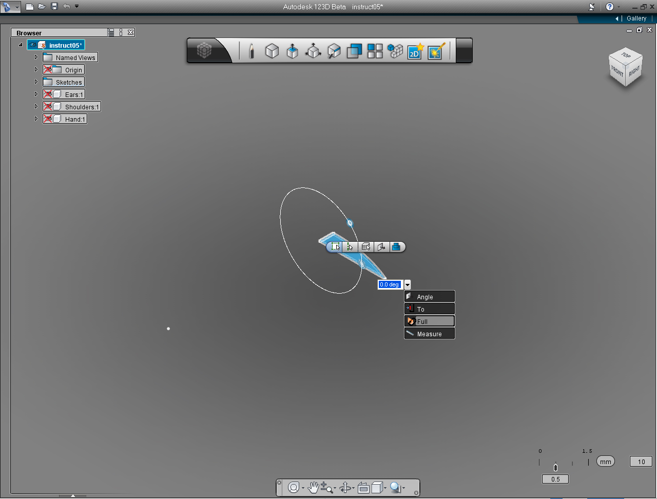
20. Click at drop down arrow next to keyboard input box, and Select "Full" function from the list.
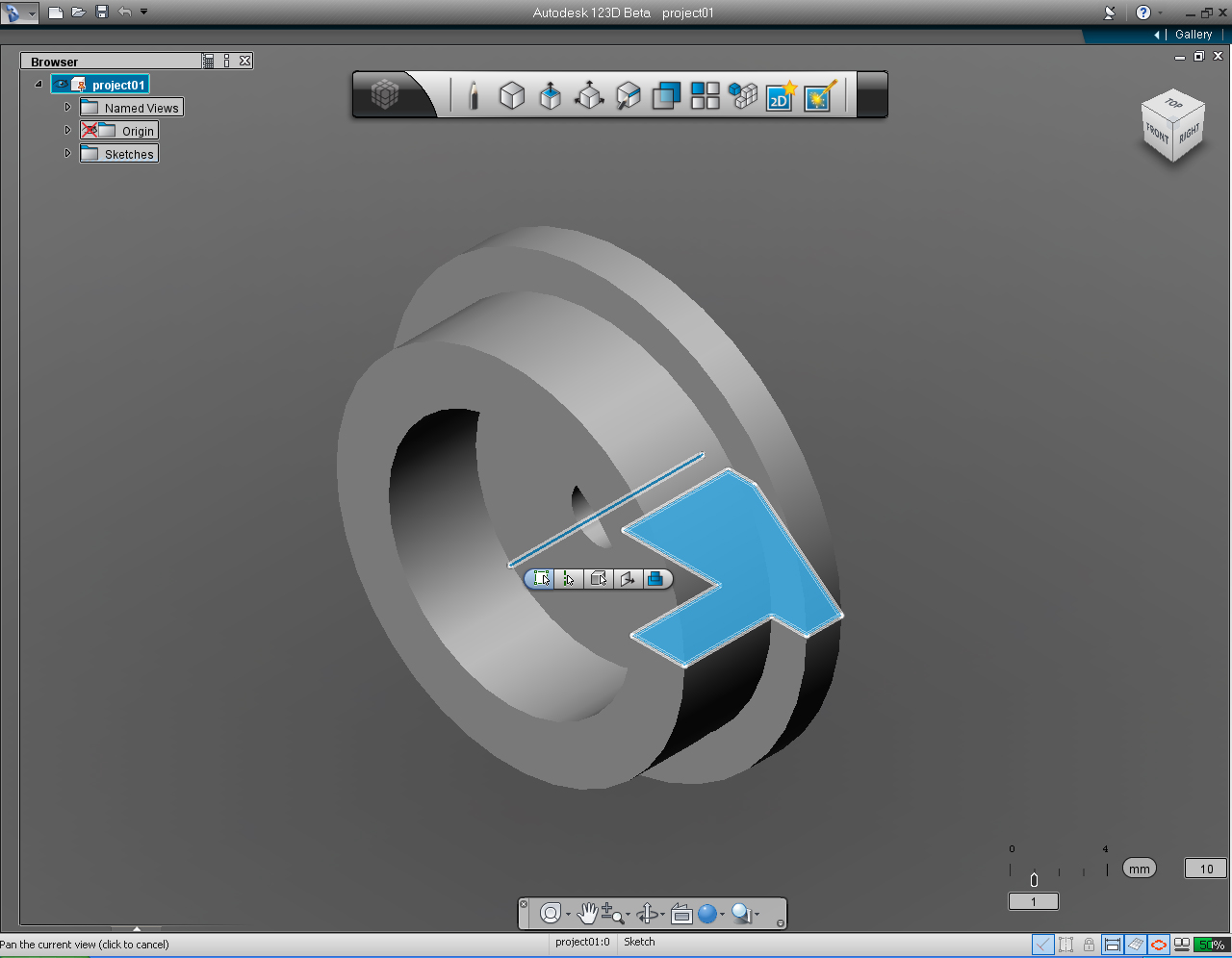
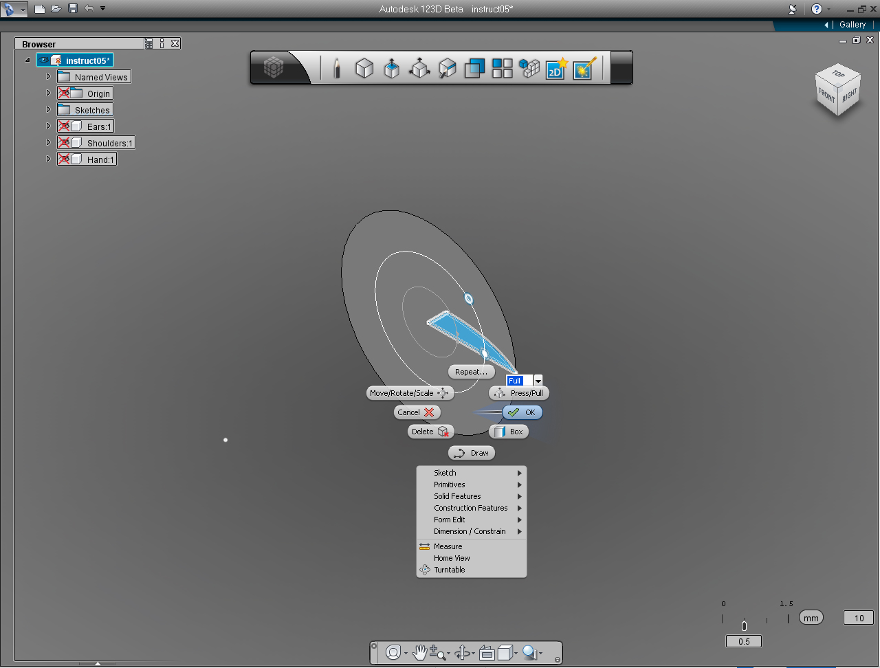
21. Now, we can see 3D model of an ear. 123D just shows you how it look like. If it is not the way we want we could go back to edit the profile at this stage. Otherwise we need to confirm with 123D that this is OK.
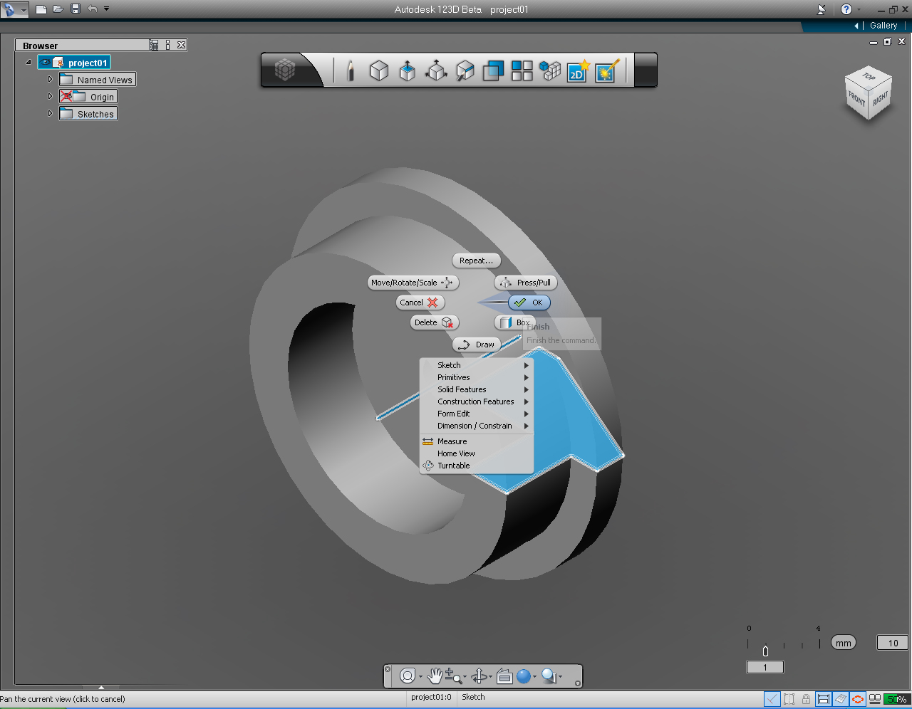
22. Right click at the solid 3D model to bring up the Marking Menu. Then left click at "OK" pill Menu to commit.
23. Now we have the first model! It a good place to save the model before starting the next Step (6).
Create Ears Cont.
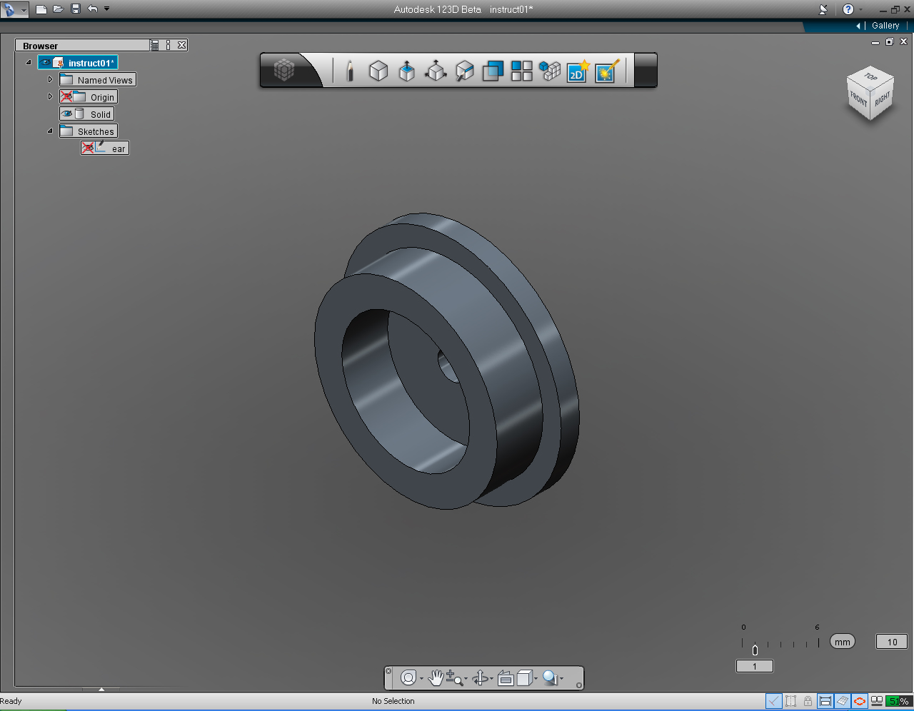
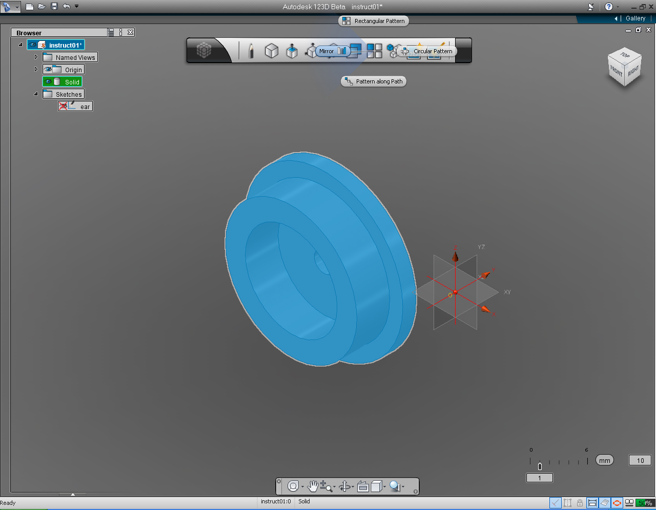
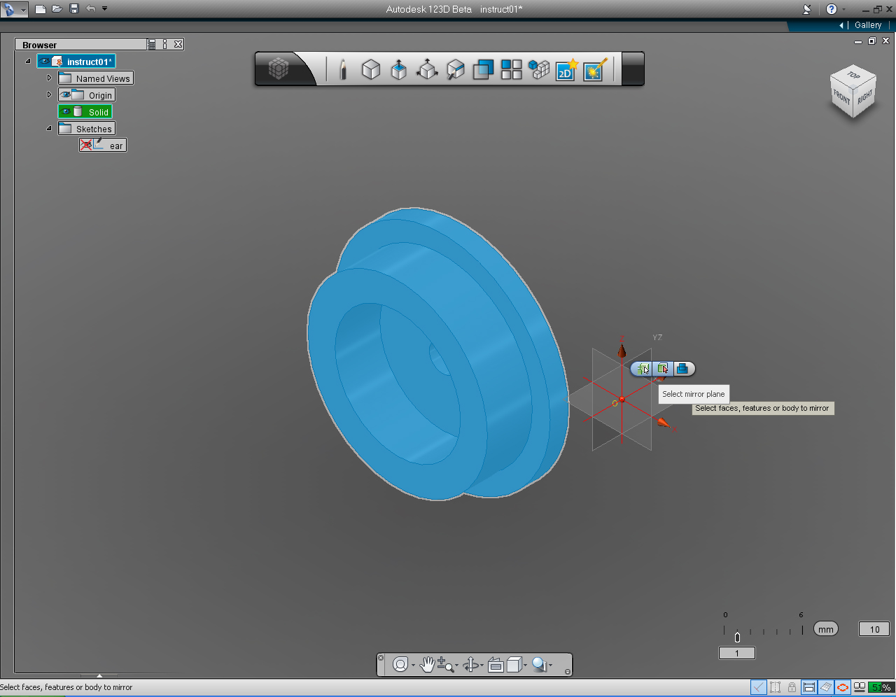
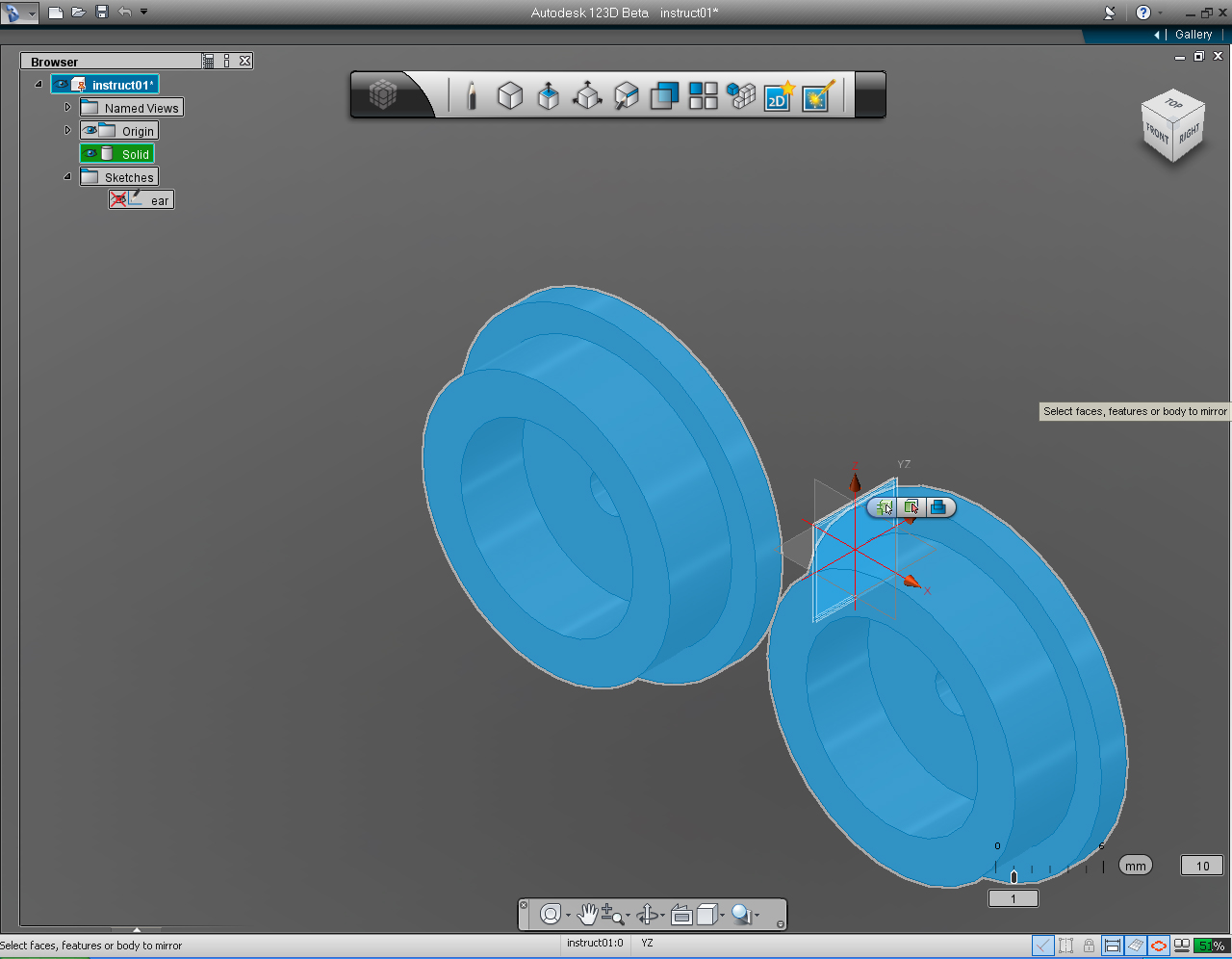
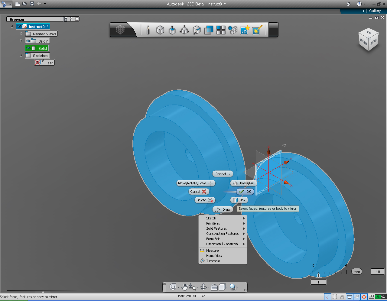
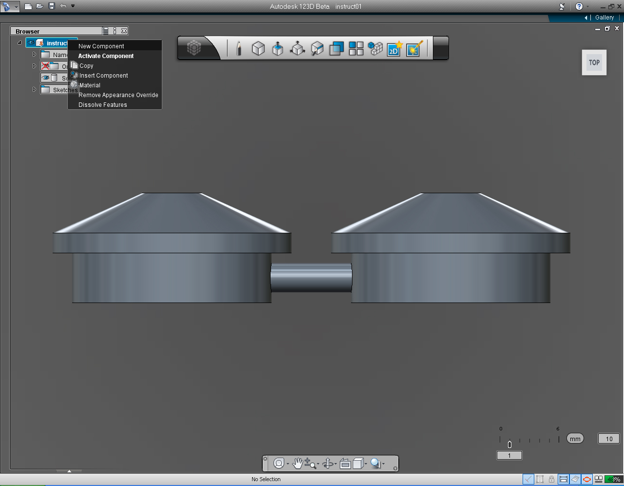
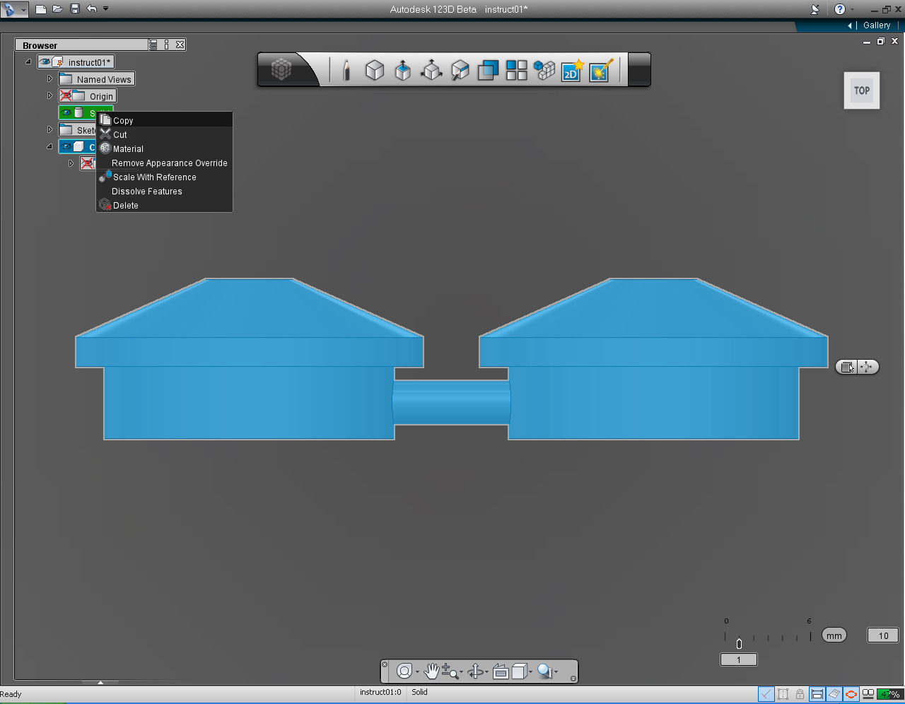
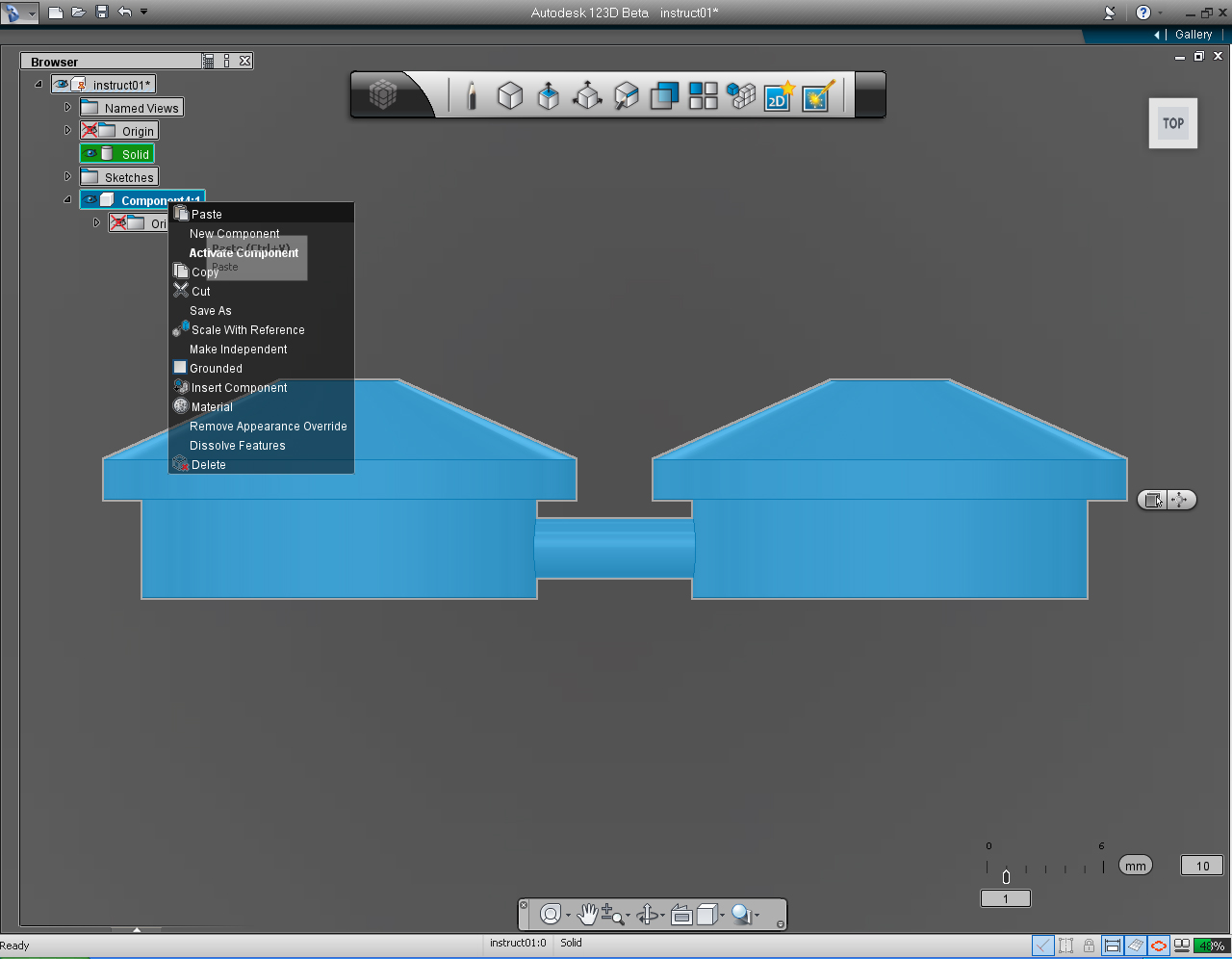
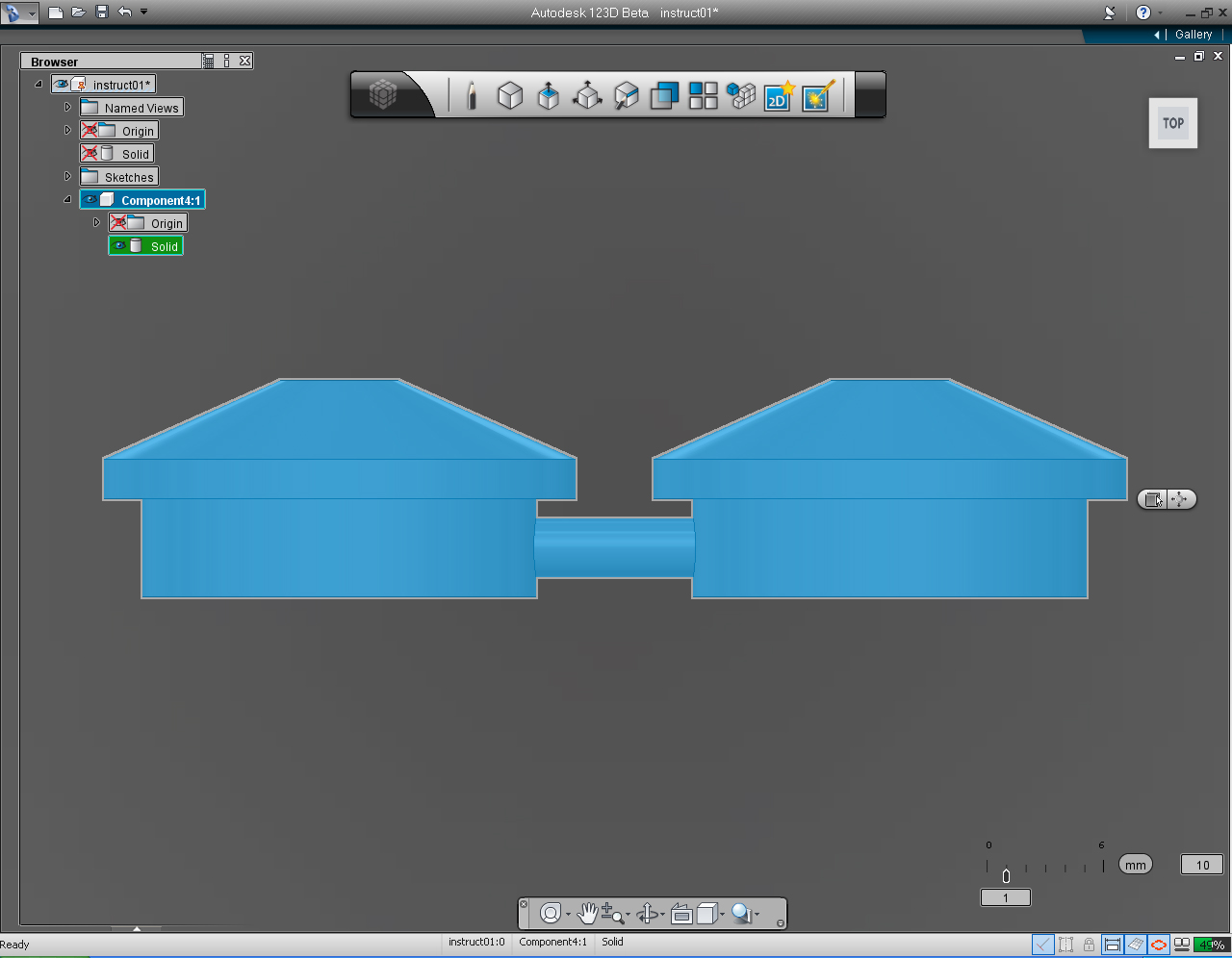
- "View Cube"
- "Move/Rotate/Scale" pill menu
- "Mirror" function in the "Pattern" Marking Menu
- "New Component" function in the "Feature Browser" Menu
- "Copy" function in the "Feature Browser" Menu
- "Paste" function in the "Feature Browser" Menu
- "Delete" function in the "Feature Browser" Menu
And these are the steps:
1. In the "Feature Browser" Menu, turn off the sketch of the ear.2. Set "View Cube" to TOP plane.
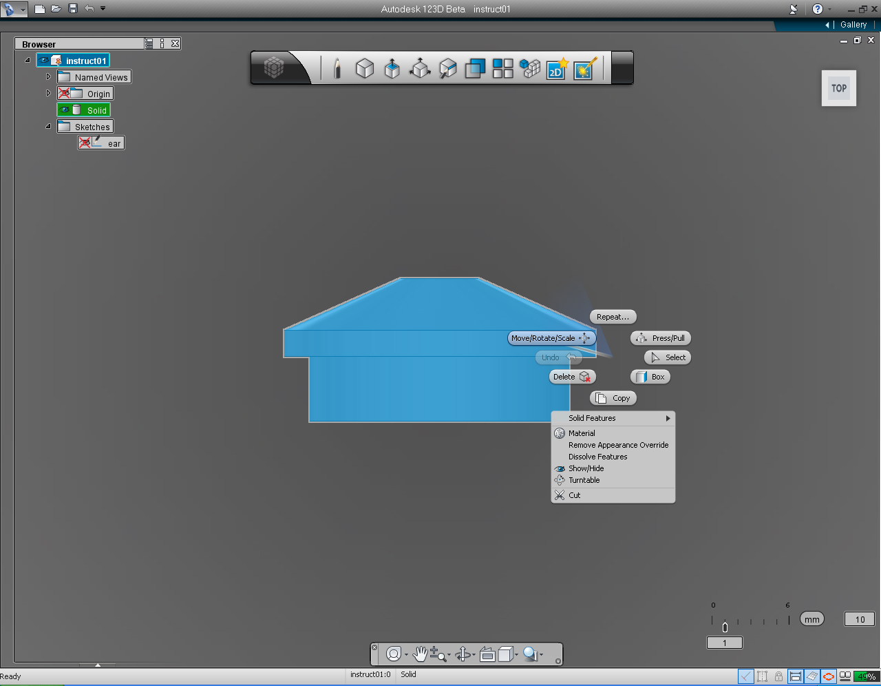
3. Hightlight solid model of ear.
4. Right click on the ear model to bring up Marking Menu. Then select "Move/Rotate/Scale" pill.
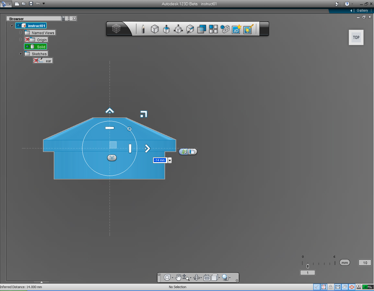
5. "Move, Rotate, Scale" Menu show up. Drag the "Right" direction arrow to the left, or enter value of -14.0 into the keyboard input box.
6. Click the Origin Folder in the "Feature Browser" Menu to "Unhide" the Origin marker.
7. Choose "mirror" pill from the "Pattern" Marking Menu.
8. After unhide the Origin, we would see the origin of the drawing plane displayed.
9. Click at the middle icon in the pill to select mirror plane, Select YZ plane on the Coordinate.
10. Unhide the Origin by uncheck the Origin checkbox, in the "Feature Browser" Menu.
11. 123D will display the mirrored ear on the opposite side of the mirror plane.
12. To commit to the mirror command, right click the mouse bottom. Then select "OK" from the Marking Menu.
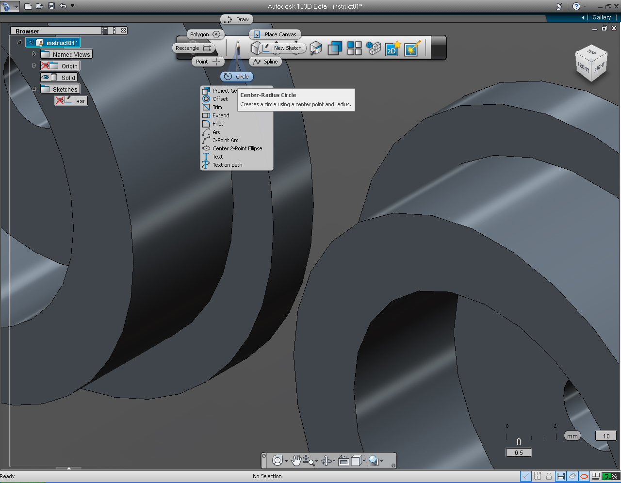
13. Now, we will connect this two ears together. Let's start to draw the "Circle" on the "Right Plane".
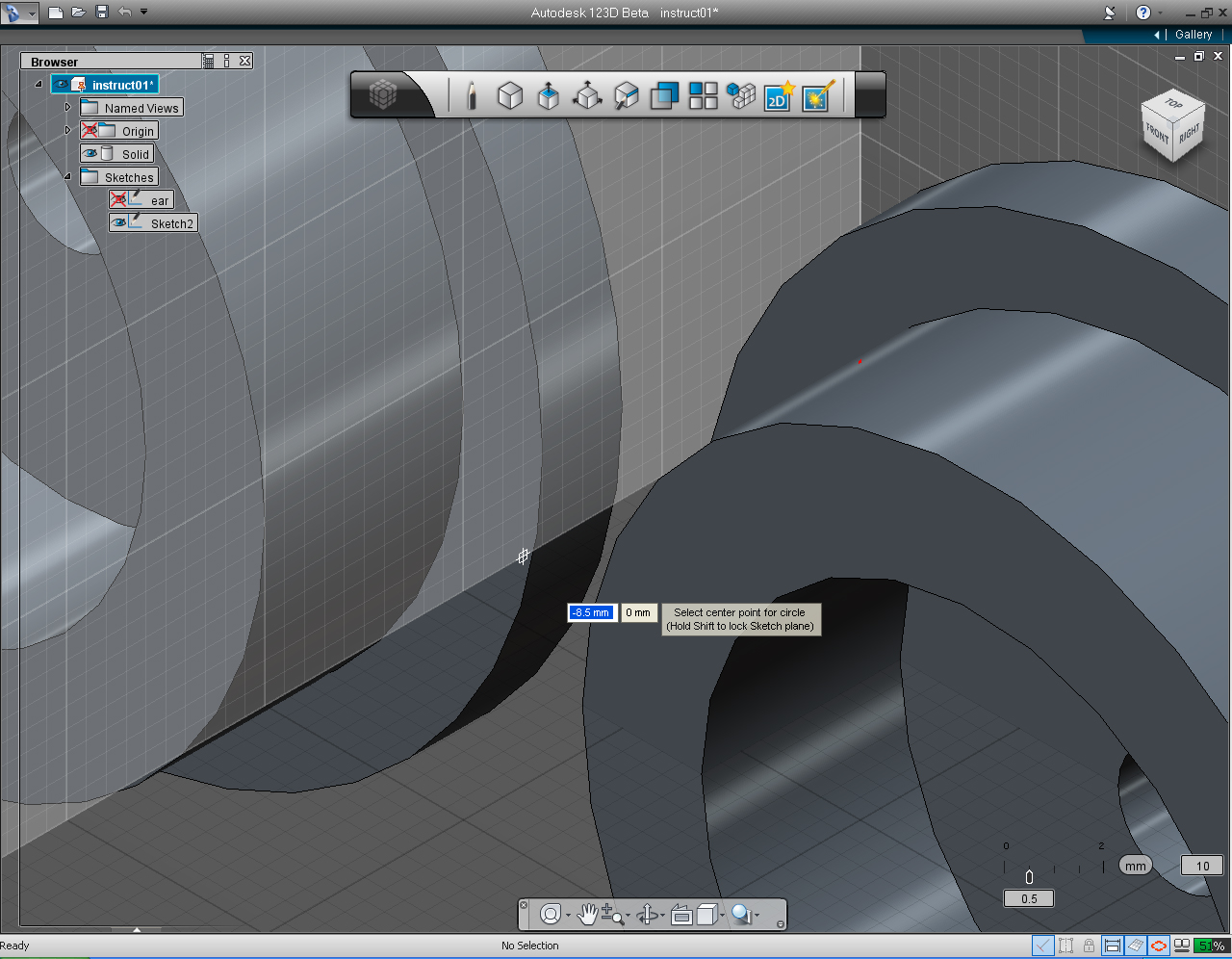
14. Set the center of the circle to -8.5 and 0.
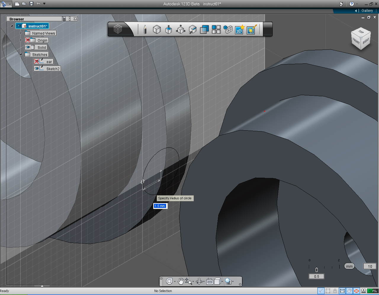
15. Assign the radius of the circle as 1.5mm
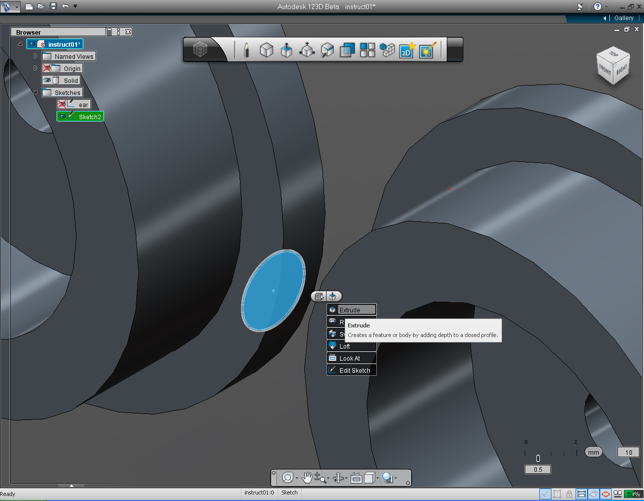
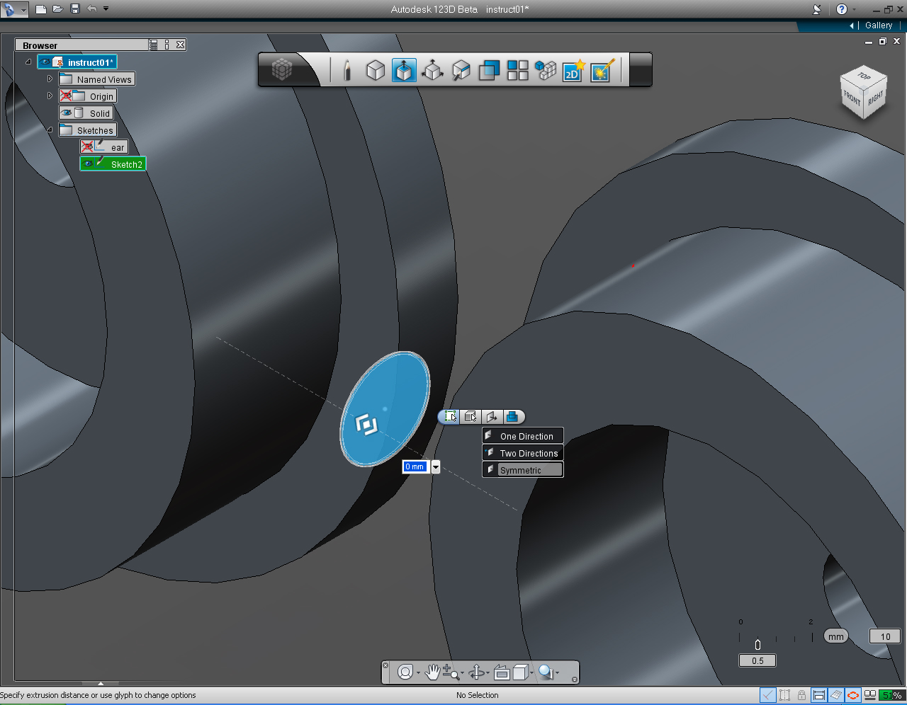
16. Select the circle that we just drawn. Right click at the circle to brign up Marking Menu, then select "Extrude" pill from the menu.
17. On the "Extrude" submenu, select the fourth or right most icon on the pill. Then select "Symmetric". This will extrude the circle in both direction.
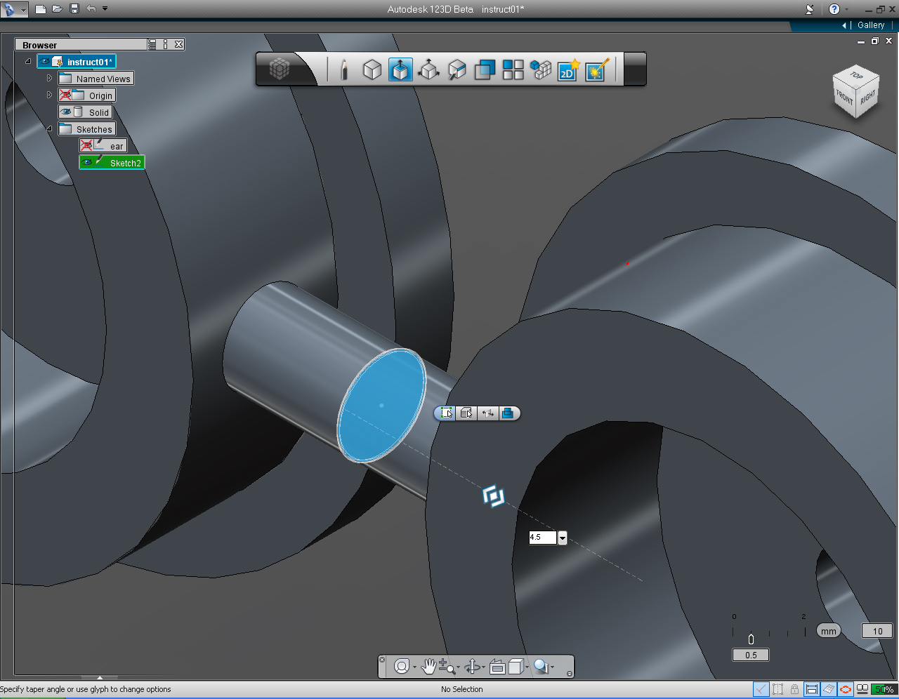
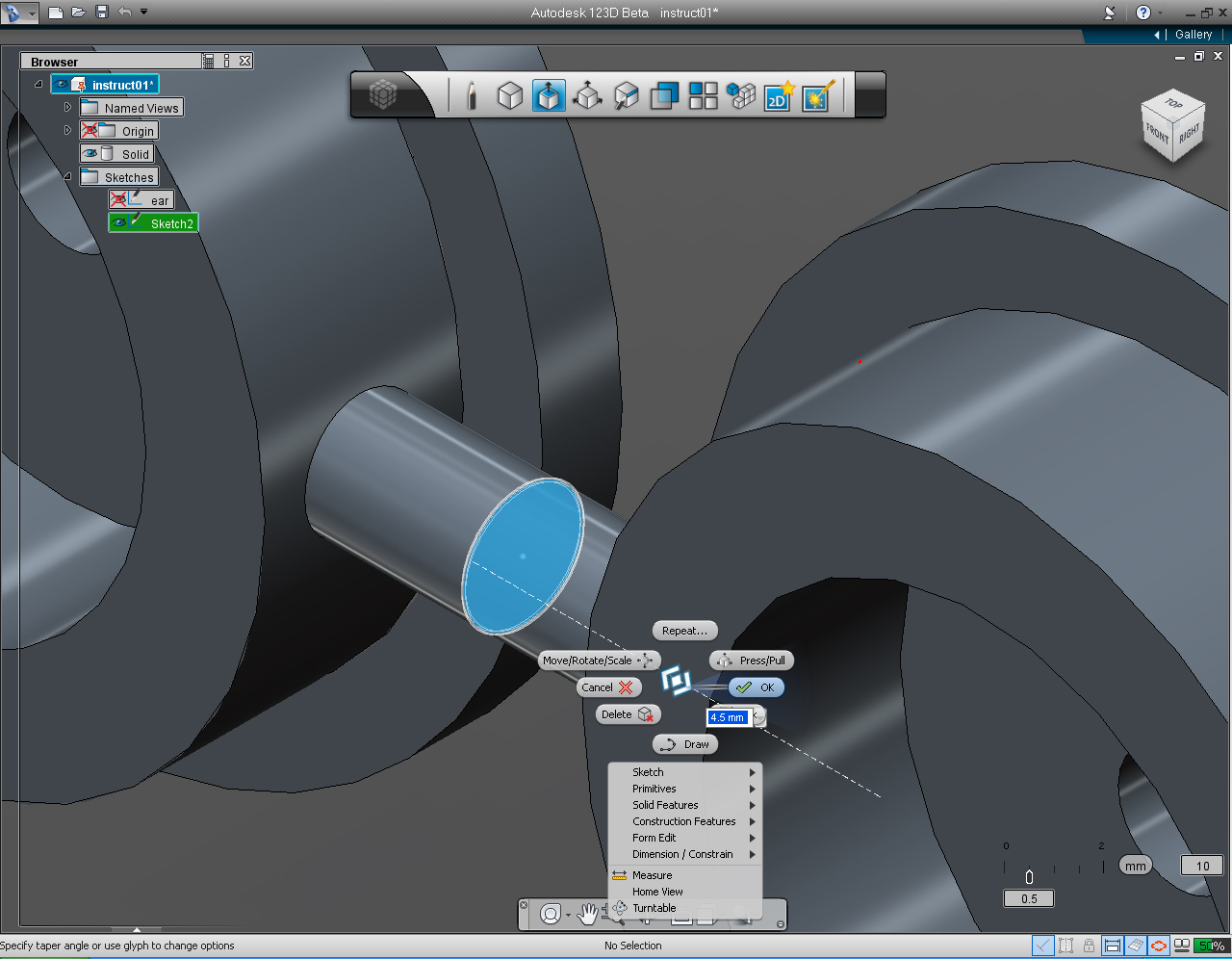
18. Drag the bidirectional arrow (or use keyboard input) to 4.5 unit.
19. Right click to bring the Marking Menu, then select "OK" pill to commit the command.
20. Change "View Cube" to TOP Plane.
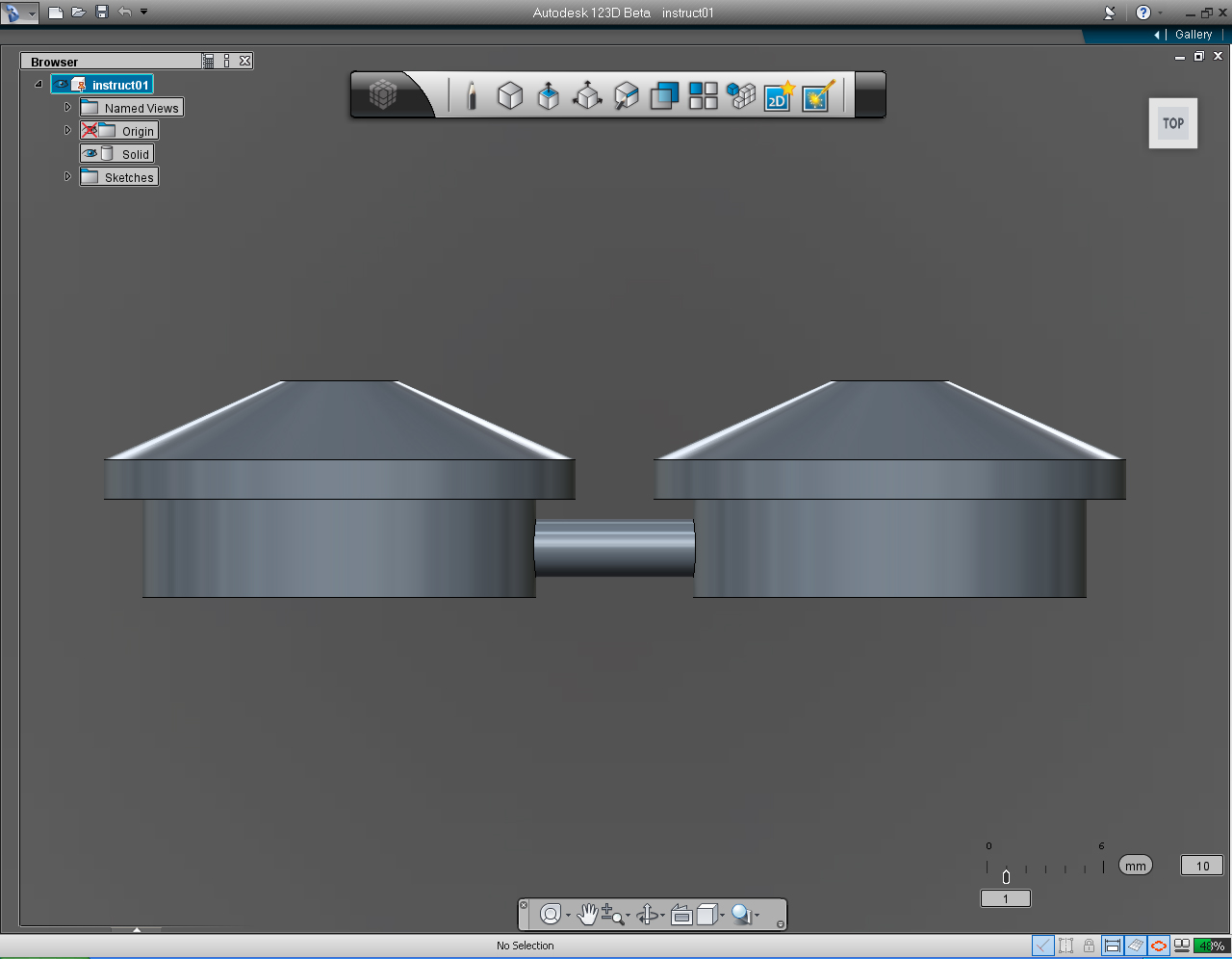
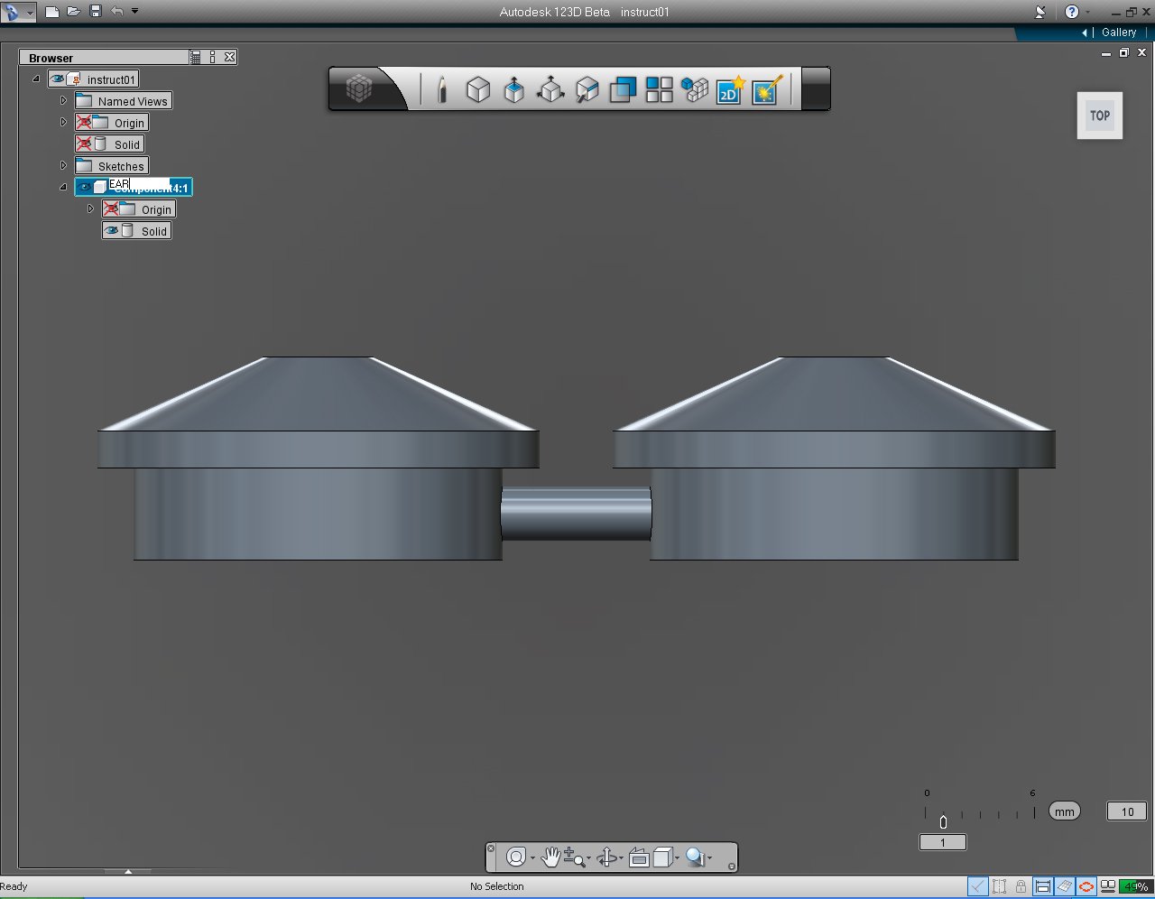
21. Now we got both ears and an extruded solid circle "joined" together. And we want to "Copy" it, and put in in separate folder-"Ear" so it would not included in the solid model we are going to create next (the shoulder).
22. Right click the first item of the "Feature Browser" Menu. And select "New Component" from the list.
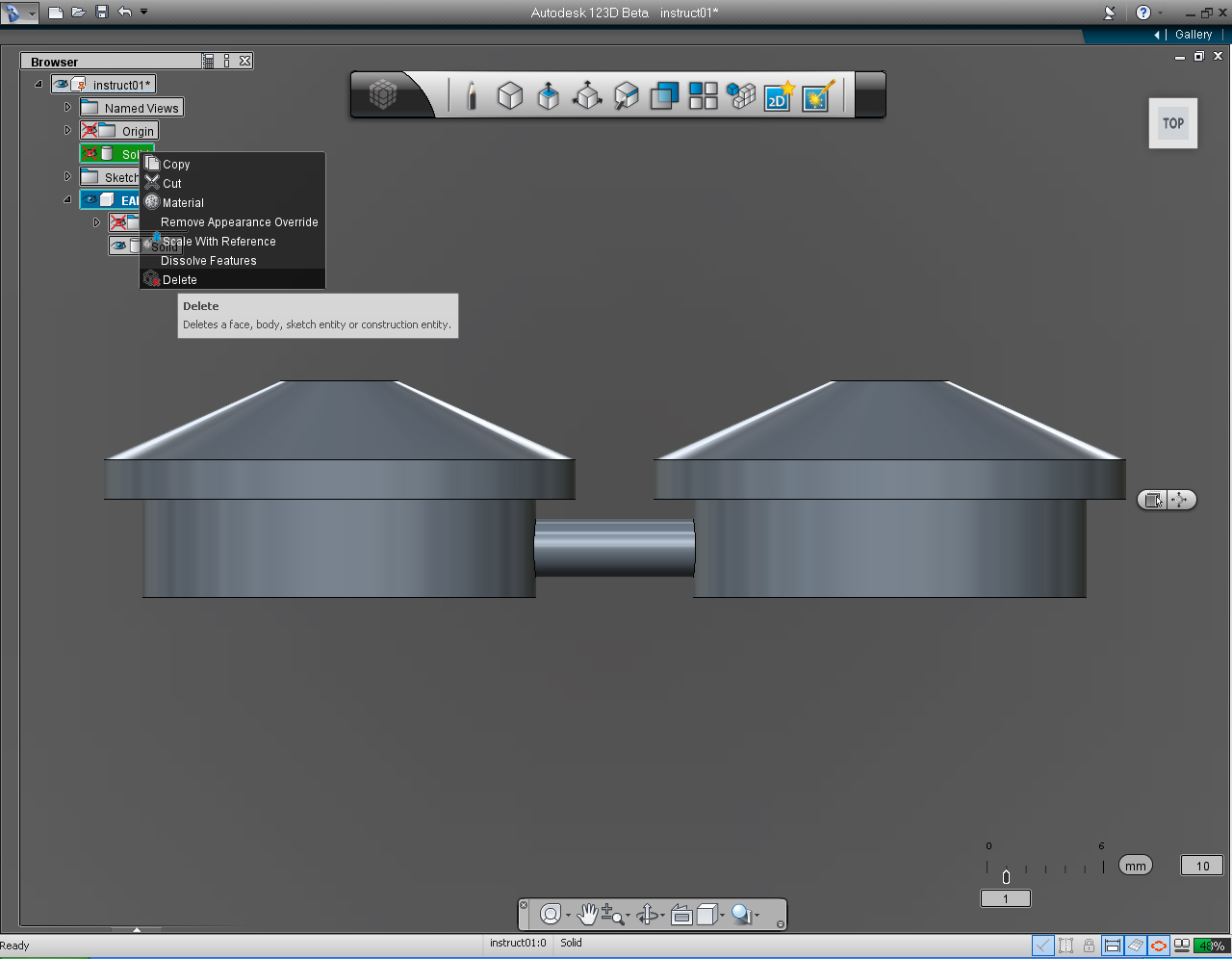
23. Click at "Solid" to select. Then right click the mouse button to bring up the drop-down list. Select "Copy" function.
24. Select the new component that we just create. Right click at it, select "Paste" function from the list.
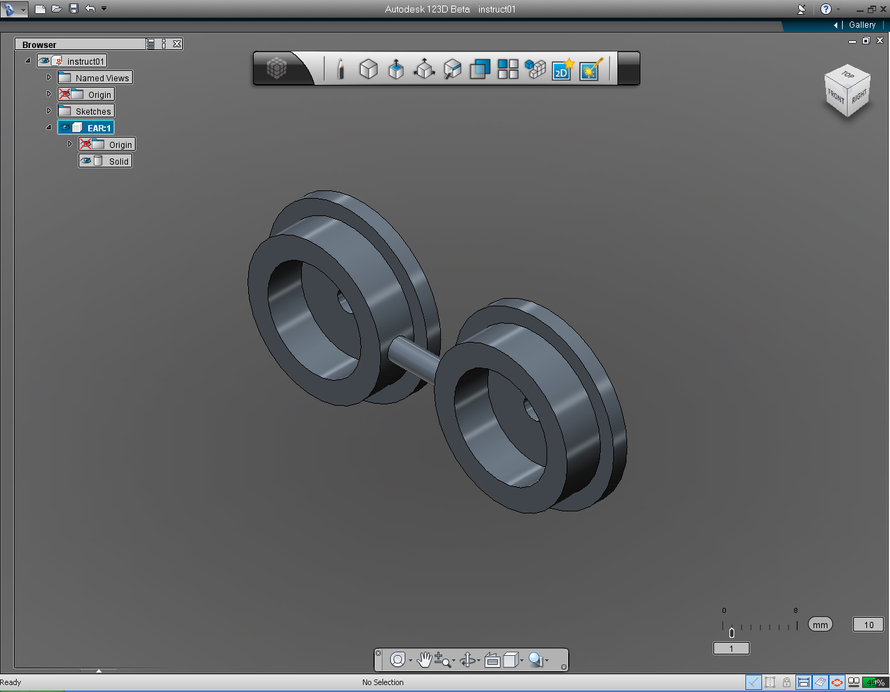
25. Now, the new component has the "copy" of ear solid model.
26. Rename the new component to "EAR".
27. Select the original ear solid model on the list. And right click the mouse to bring the list menu. Click at the "Delete" function to delete the original solid model.
28. Now, the ears model is completed!
And it's a good time to save the file.
Create Shoulders


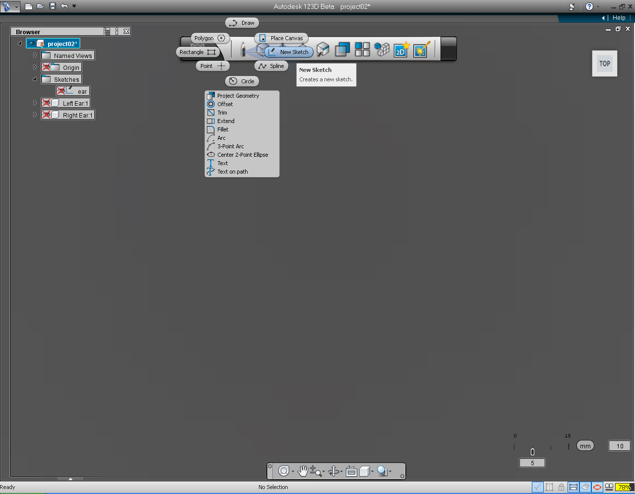
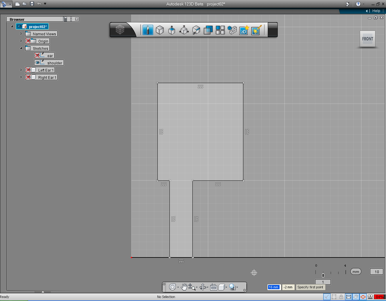
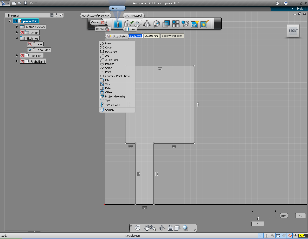
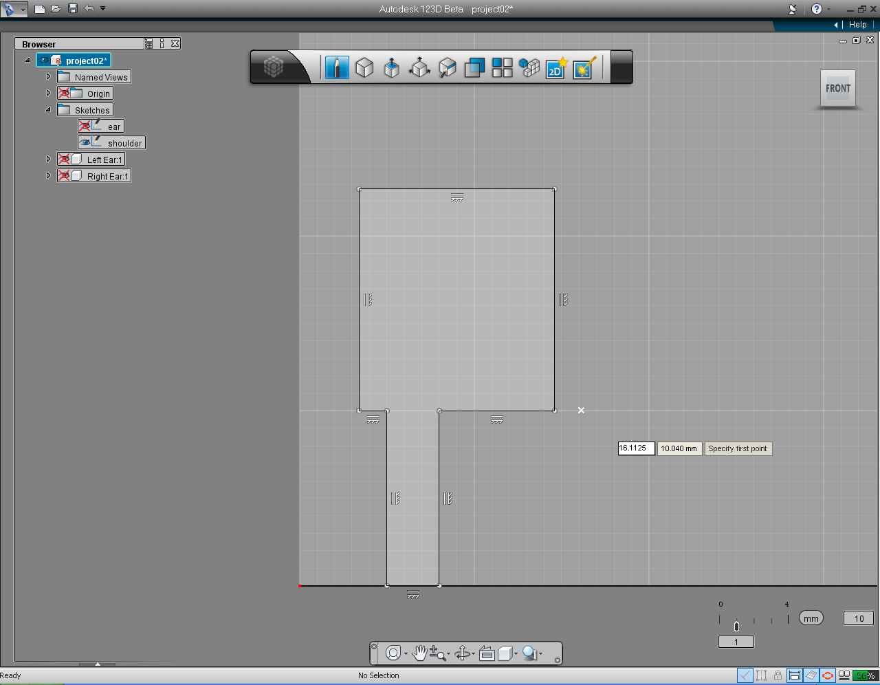
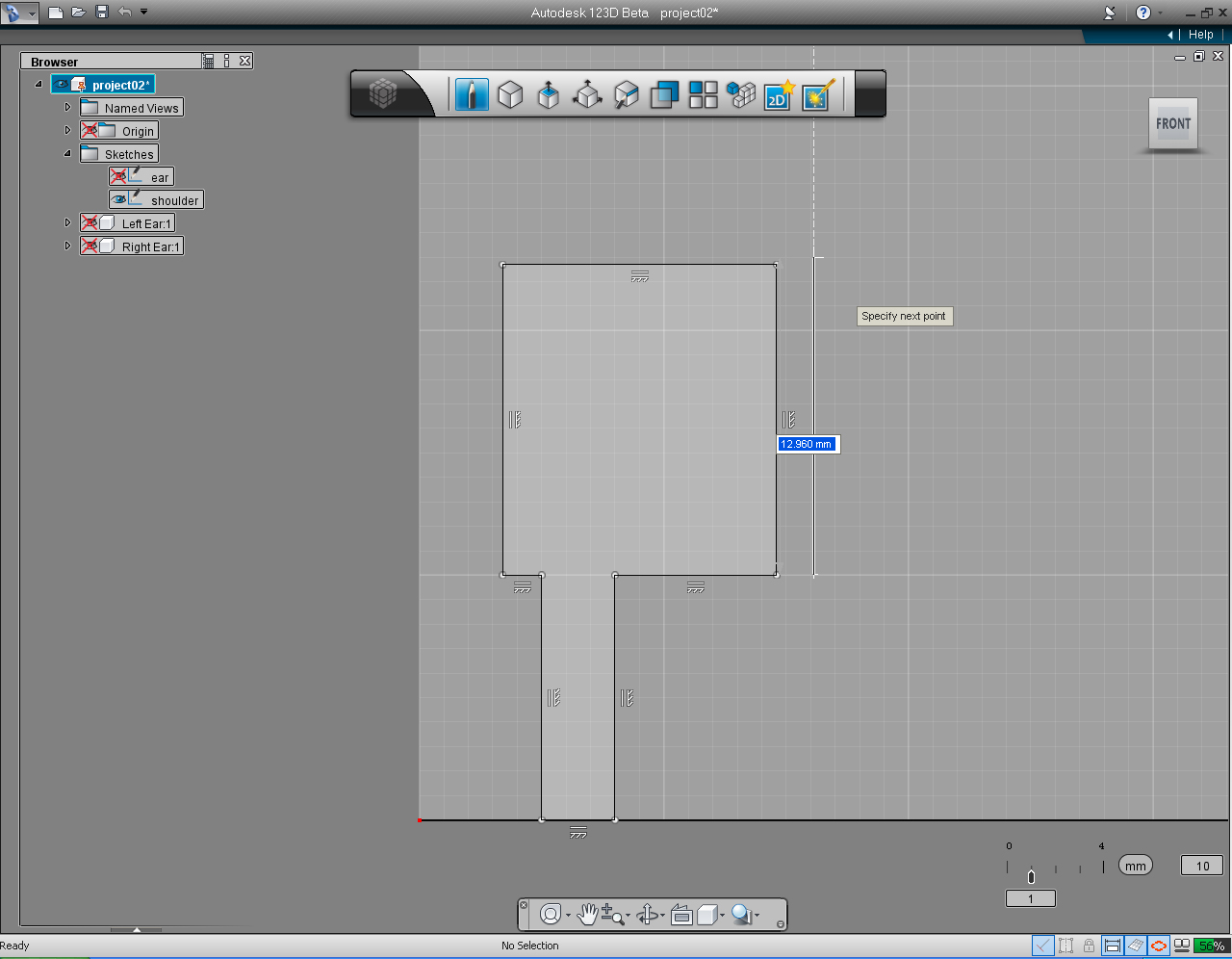
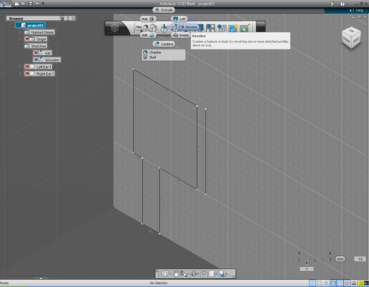
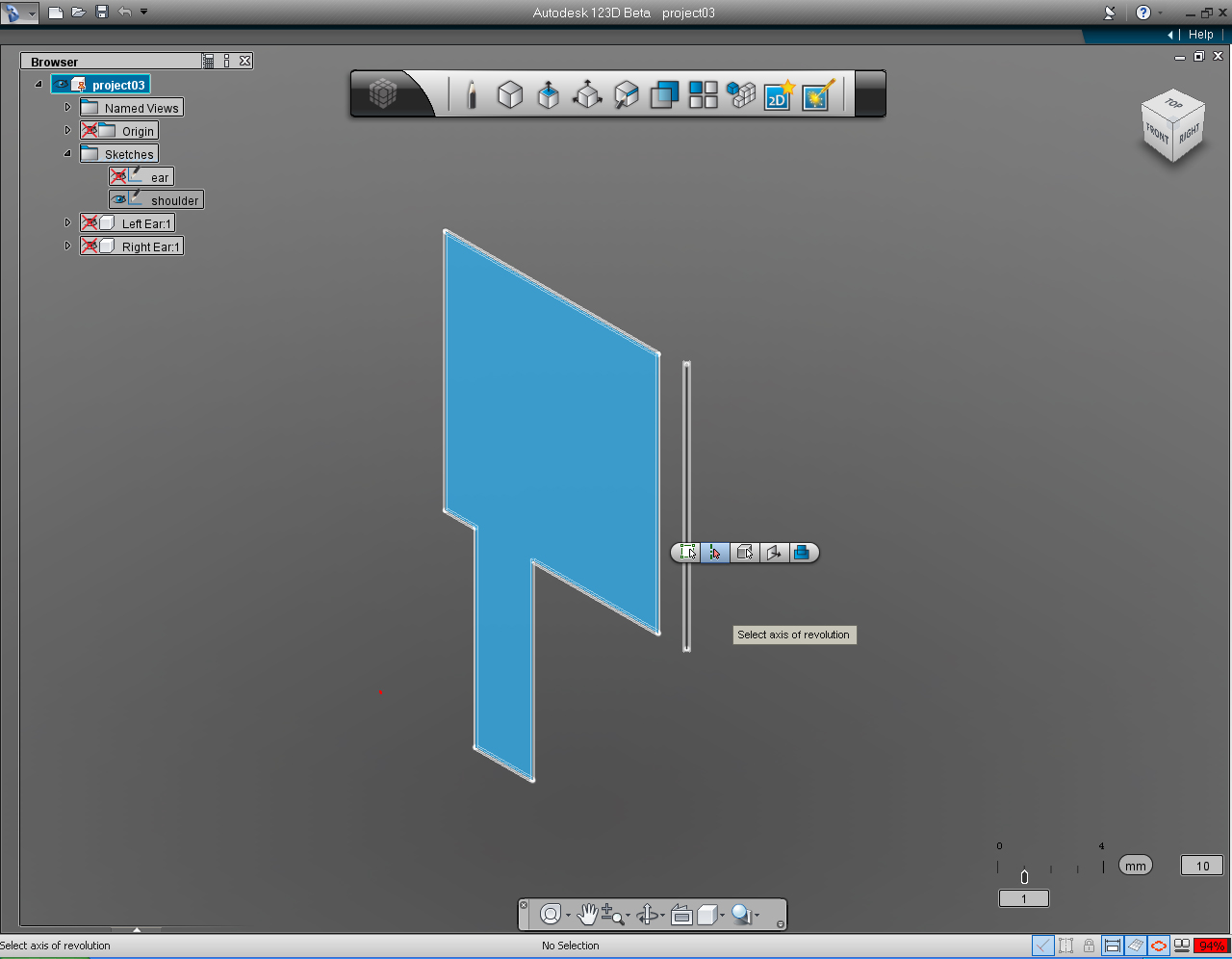
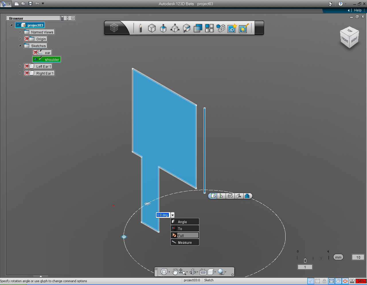
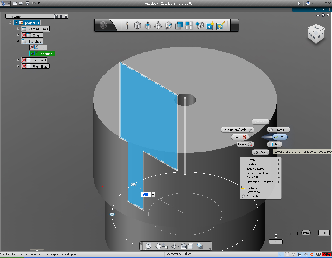
- "Sketch Plane" sub menu in "New Sketch" pill on "Sketch" Marking Menu
- "Draw" pill function in "Sketch" Marking Menu
- "Repeat" pill function in "Sketch" Marking Menu
- "Revolve" function in the"Create" Marking Menu
- "Snap Menu"
- Keyboard Input
- Navigating Drawing Screen with Hand Tool and Mouse Scroll (middle) Button.
And these are the steps:
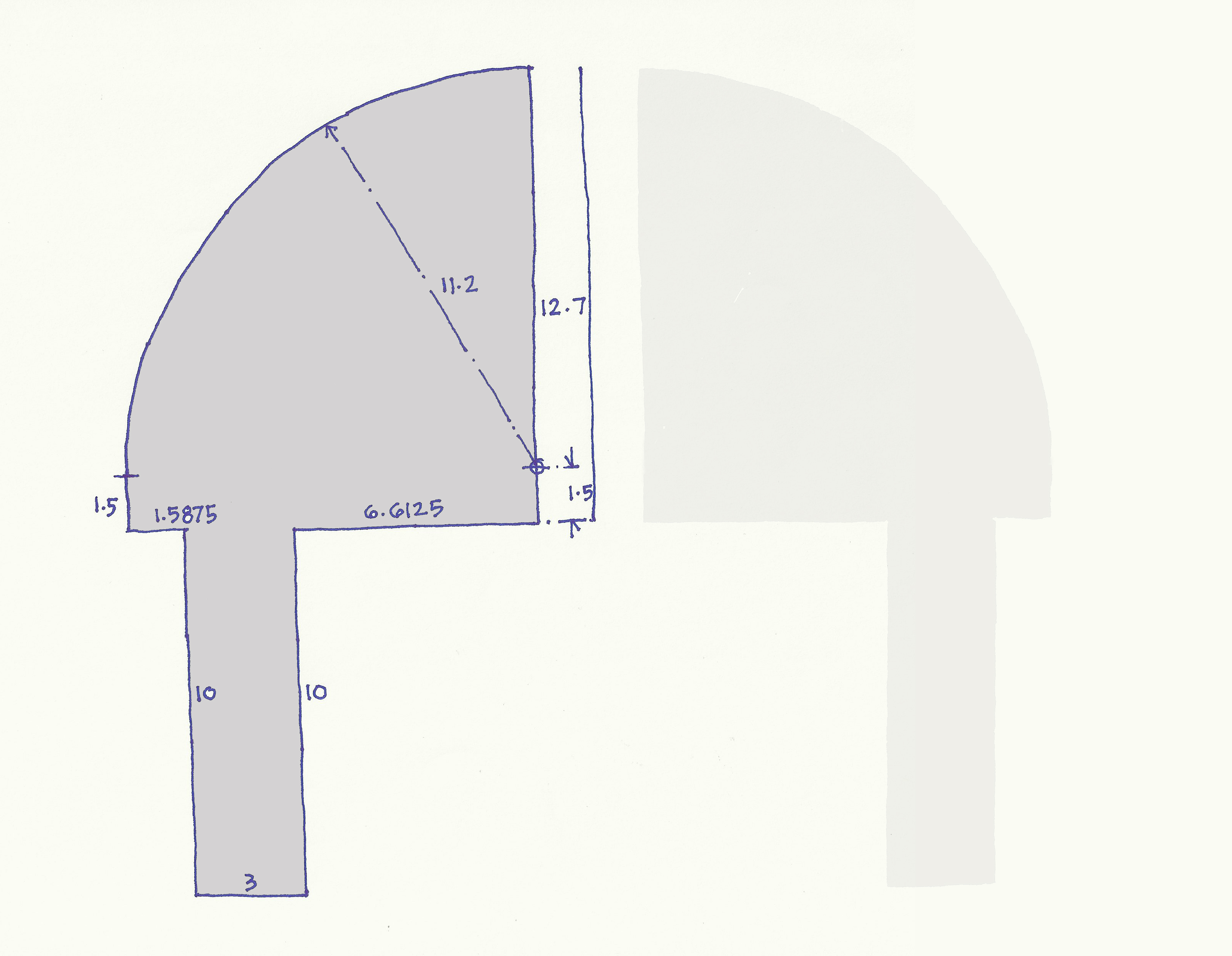
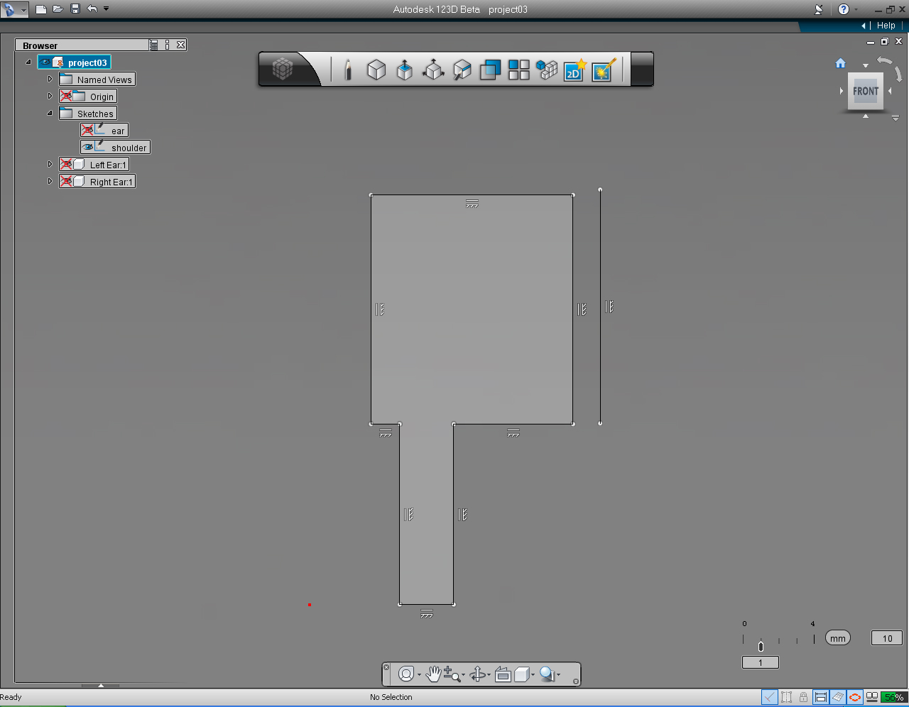
1. Rendering of the shoulder 3D model that we are creating.
2. Cross-section or profile of the shoulder, with dimension to be drawn in 123D
Continue working on the same file as in last Step,
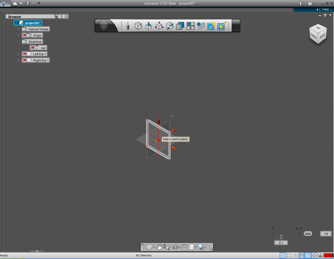
3. On the "Sketch" Marking Menu, select New Sketch pill function.
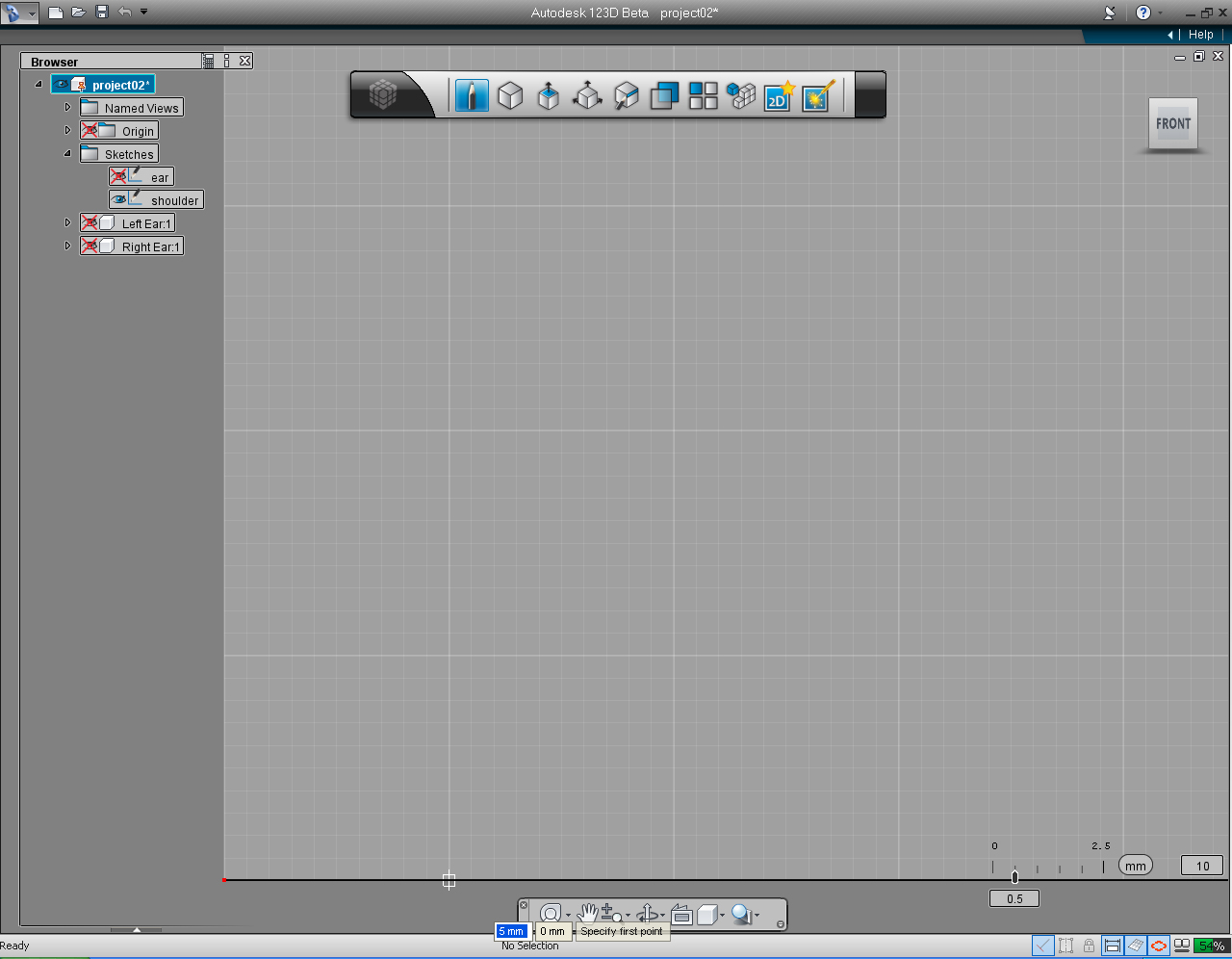
4. Select XZ plane on the Origin Coordinate or "Front" plane (plane on XZ)
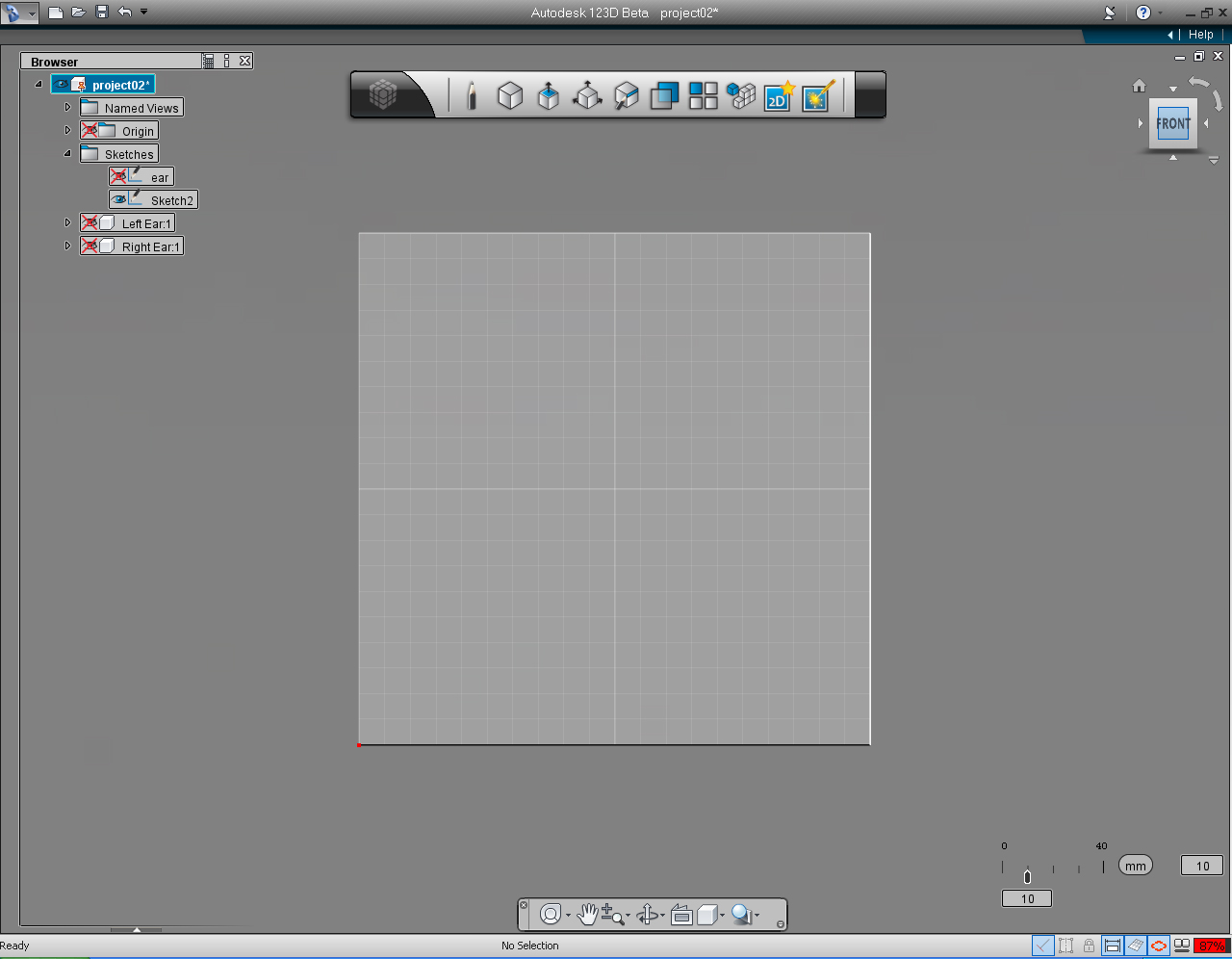
5. Set "View Cube" to the FRONT view.
6. The front plane appears with the Origin is on the lower left corner (red dot).
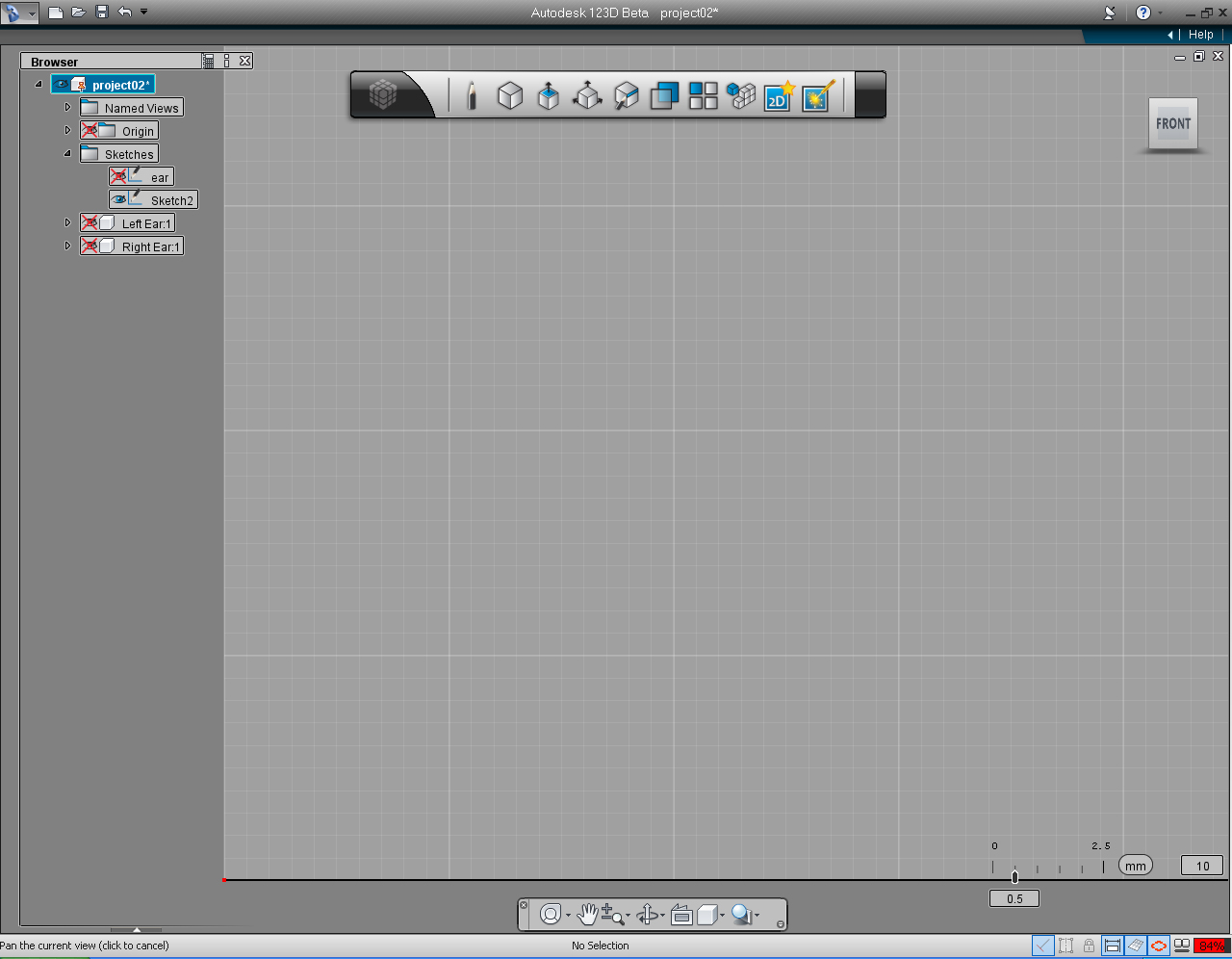
7. Right click on the mouse, to drag the drawing plane closer. Until the Snap value in the Snap Menu display the amount of 0.5
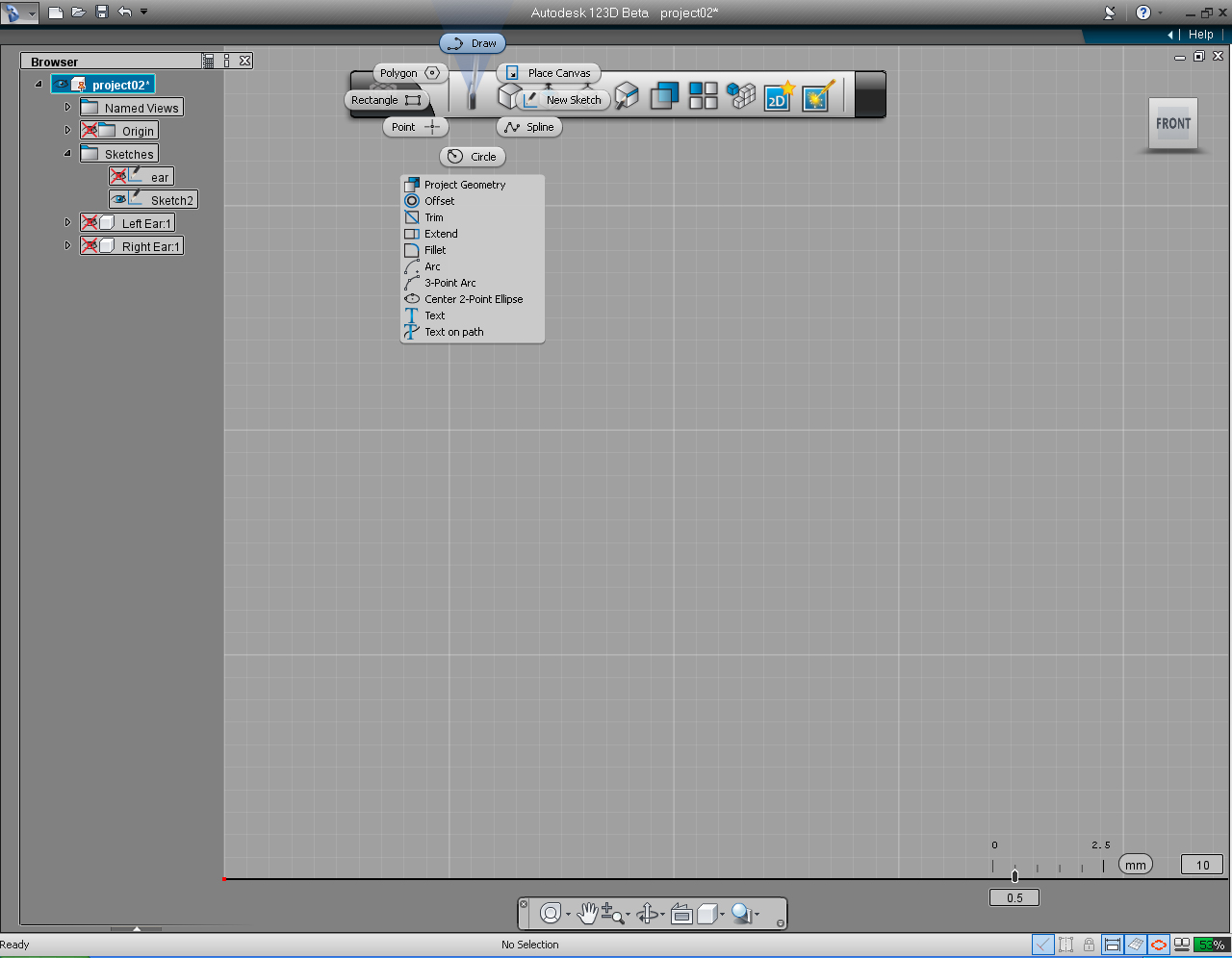
8. Select "Draw" pill in t he "Sketch" Marking Menu
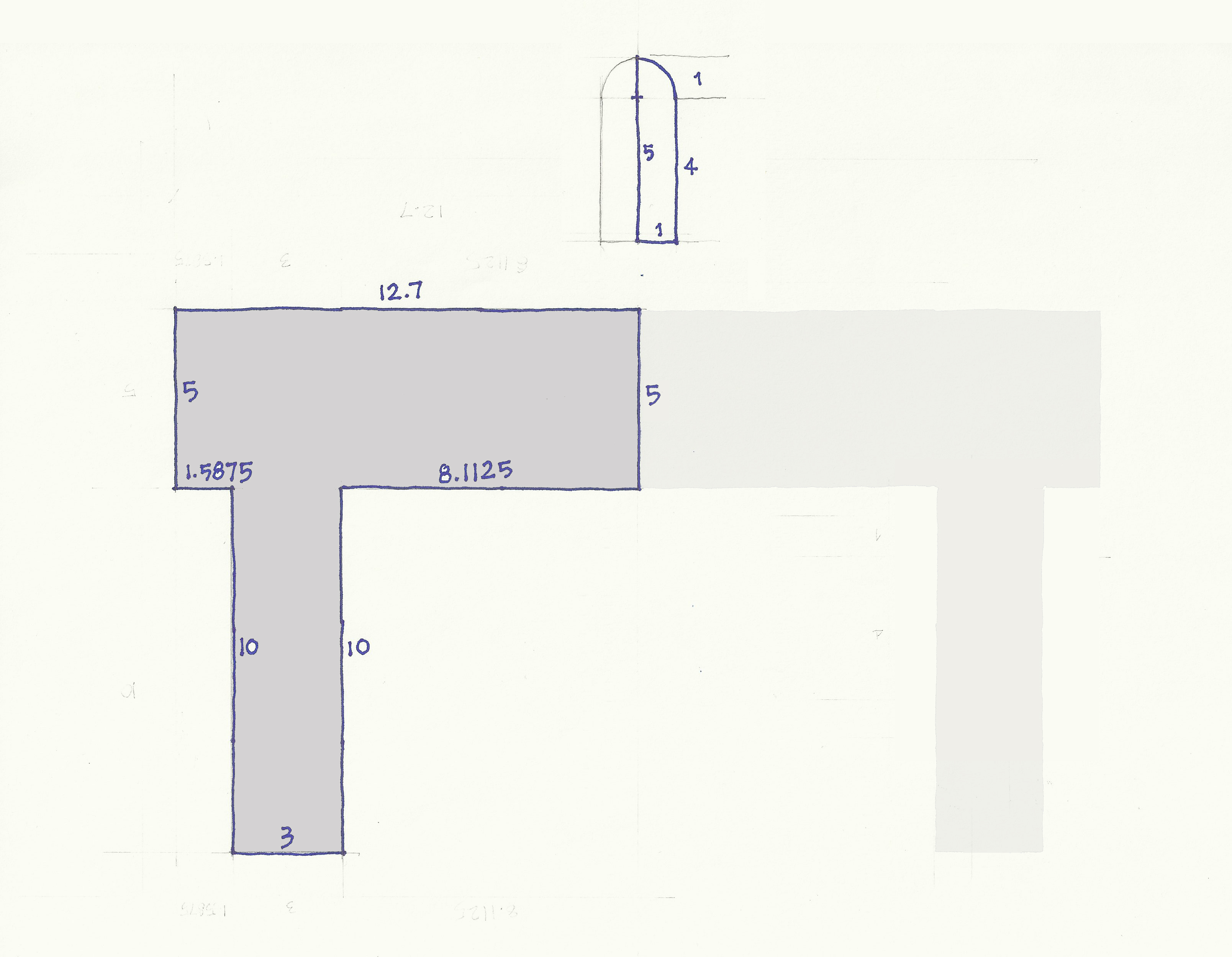
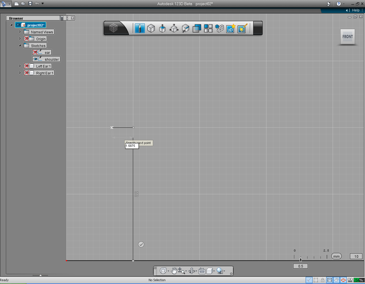
9. Set the starting point at 5mm and 0mm. Then draw the straight line upward at 10mm long.
10. And draw a perpendicular line to the previous line by draw the end point to the left, and input the amount of 1.5875mm using the keyboard input.
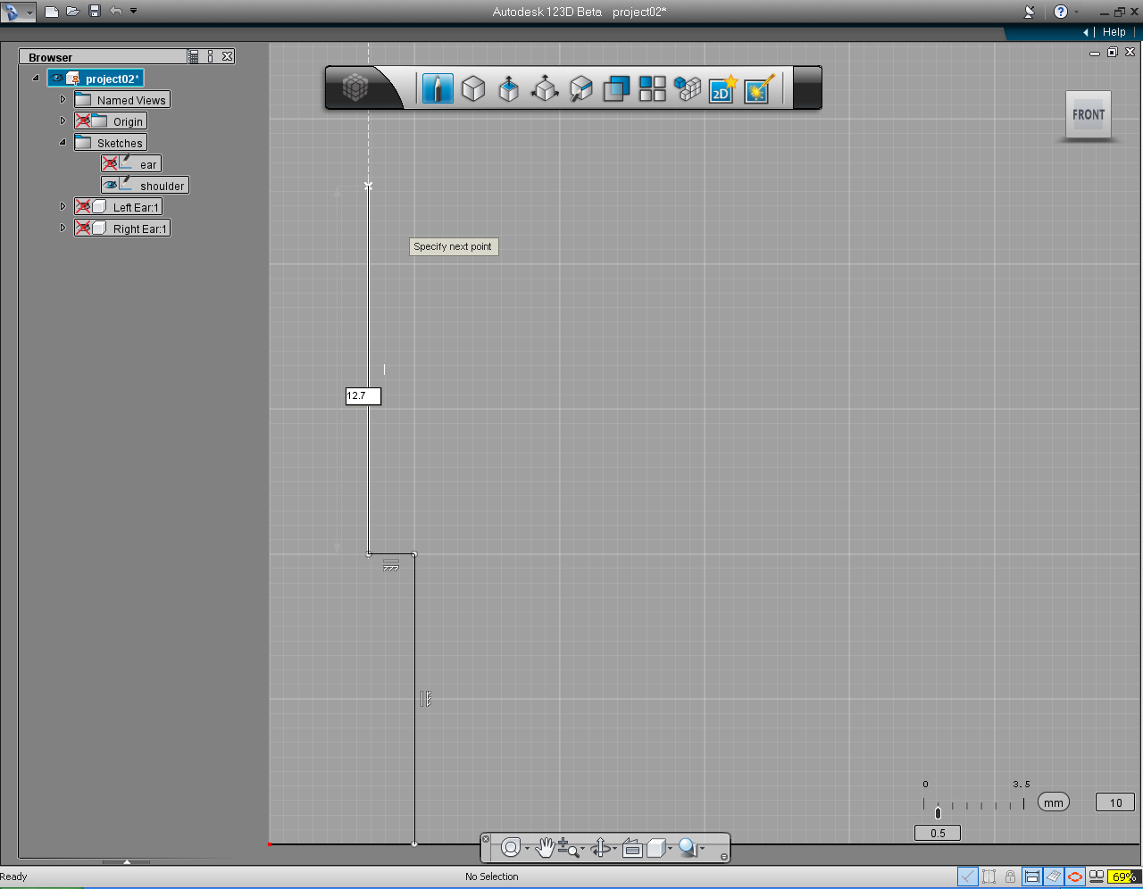
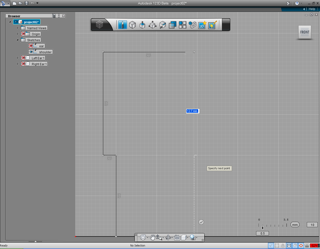
11. Continue to draw the line in upward direction, using the keyboard input to enter 12.7 for the length of line.
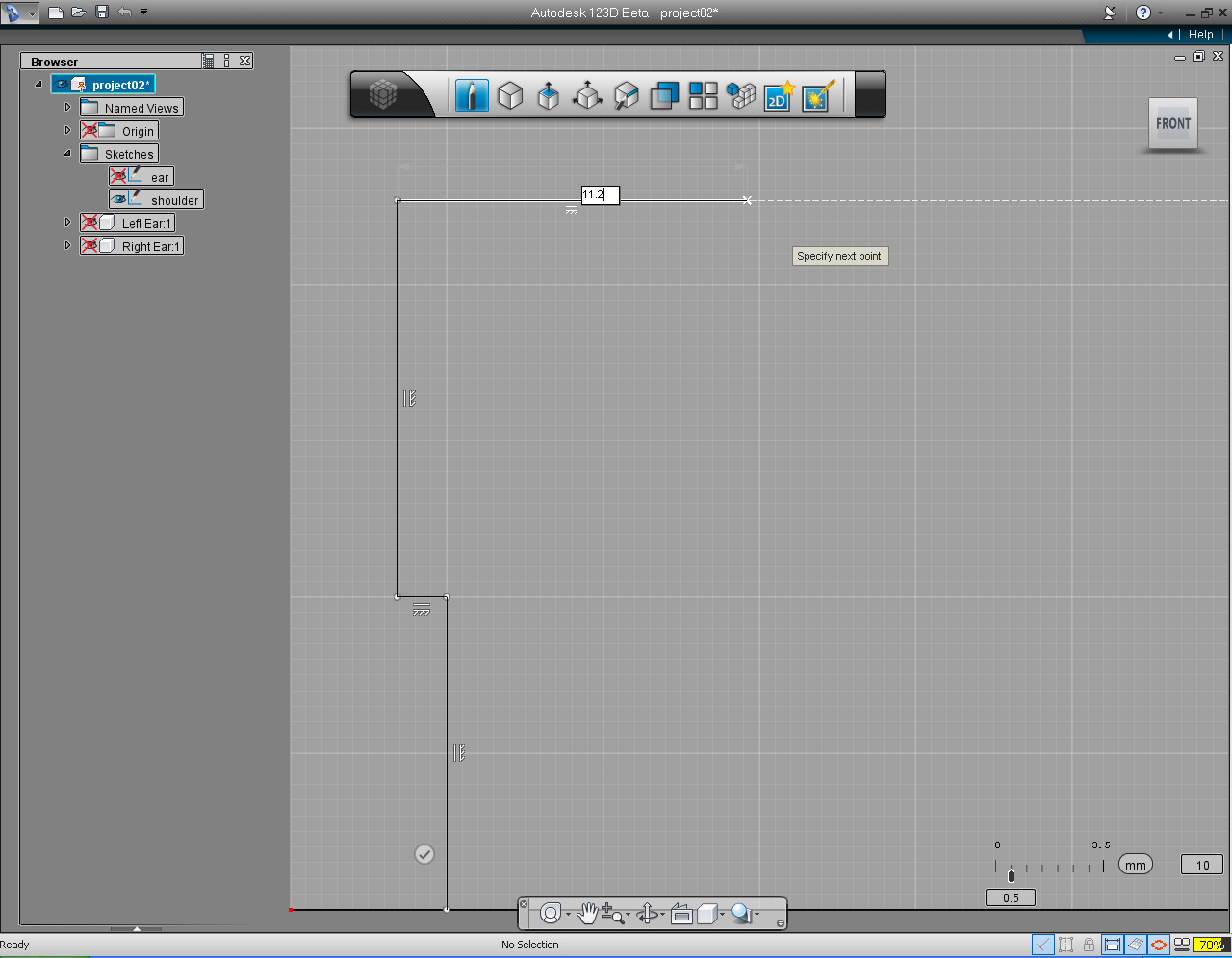
12. Drag the endpoint of line in the Y direction (toward the right), and enter the length of the line as 11.2mm.
13. Drag the next endpoint downward, and enter 12.7mm for the length of the line.
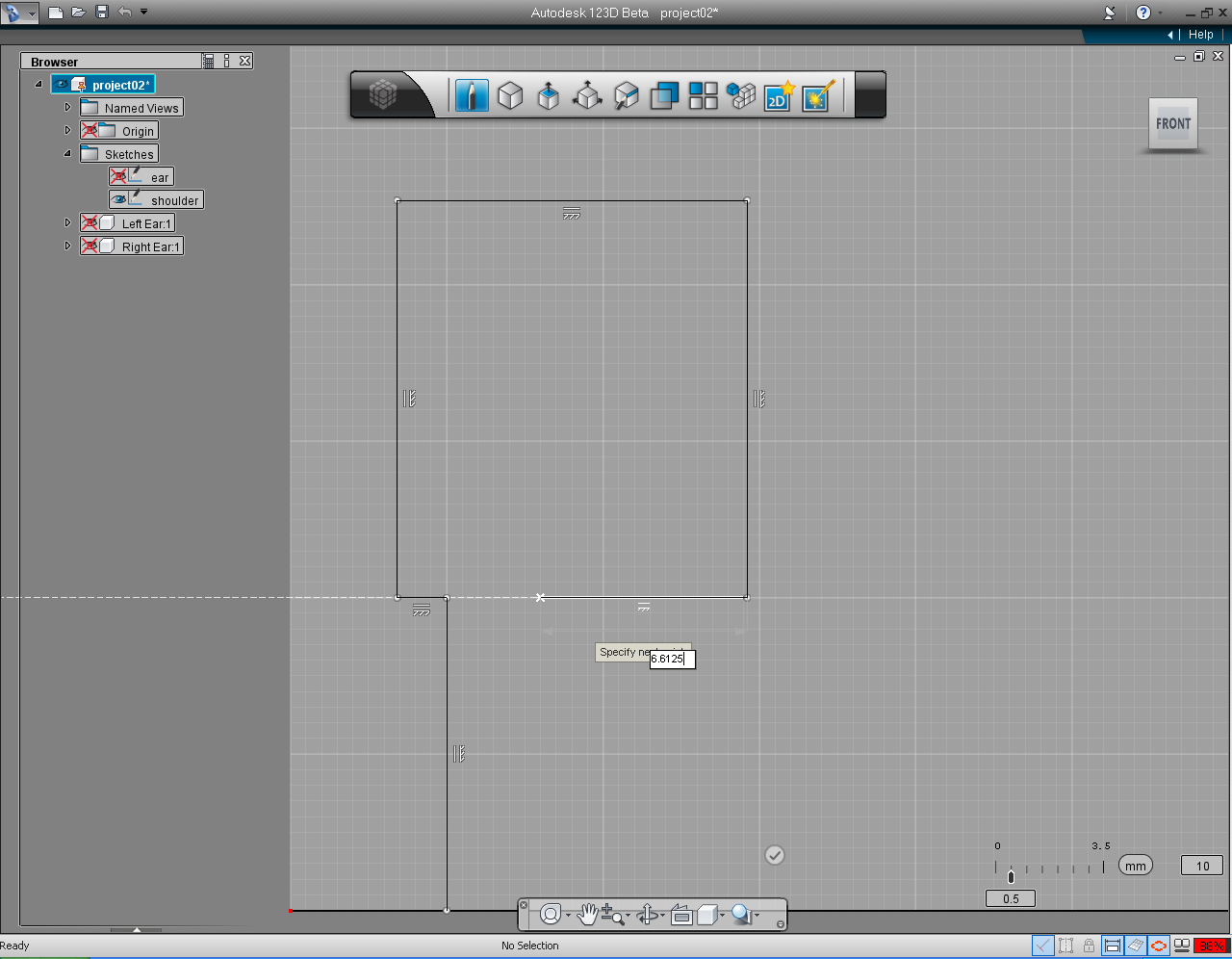
14. Drag the next endpoint toward -X direction (to the right), and enter the value of 6.6125 for the length.
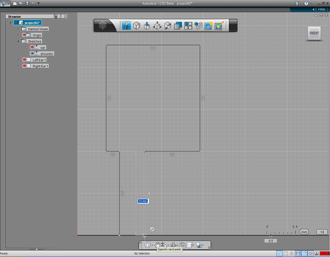
15. Drag the next endpoint of the line toward -Y direction (downward) and enter 10 for the length of the line.
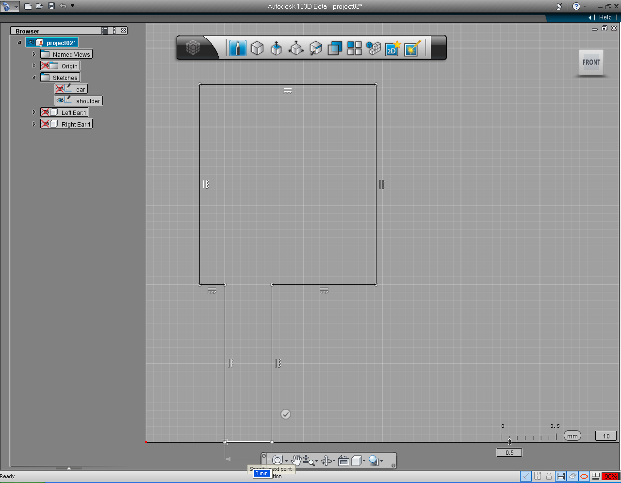
16. Then join the next end point to the start point of the profile.
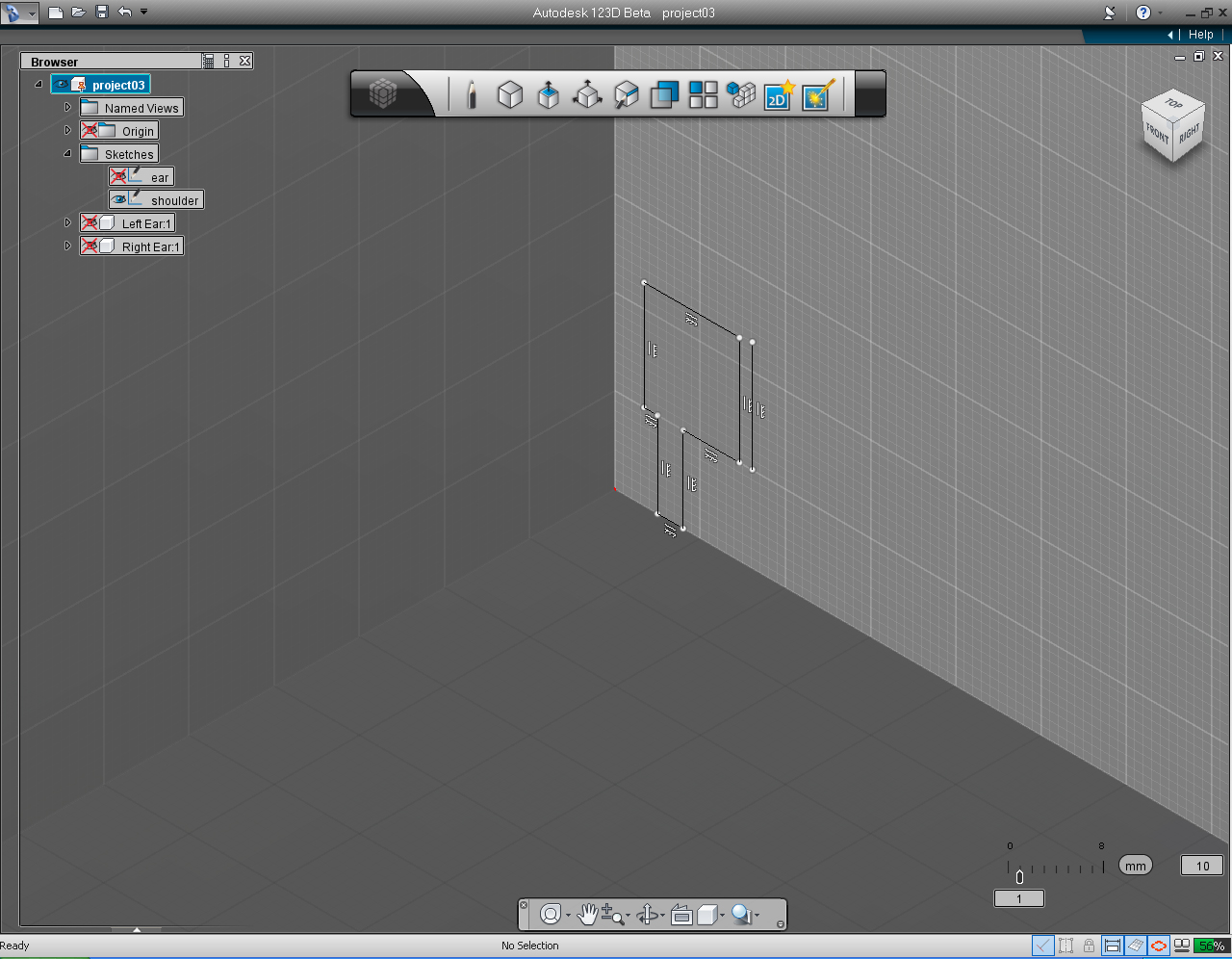
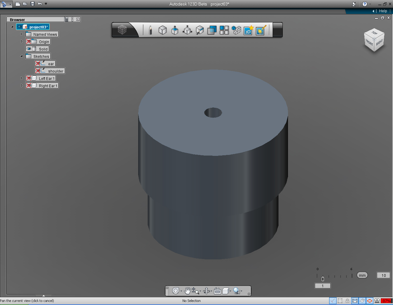
17. We now got the cross-section of the shoulder. Next, we will revolve the profile to create solid model.
18. Before we could "Revolve" the profile, we need to draw the revolving axis first. Select "Repeat.." pill on the "Sketch" Marking Menu.
19. Set the starting point of the line at the position of 11.1125 and 10, by using the keyboard entry.
20. Drag the endpoint of the line upward. And enter the length of the to any amount you preferred.
21. We are done with the shoulder profile. And ready to make a "revolve" the profile to make solid model. It a good time to save the file now.
22. Use "View Cube" to set to "Home" view.
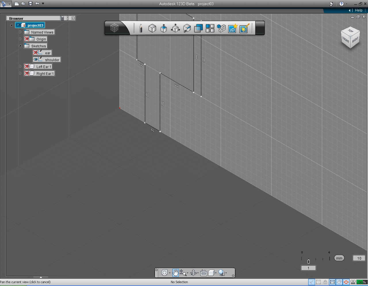
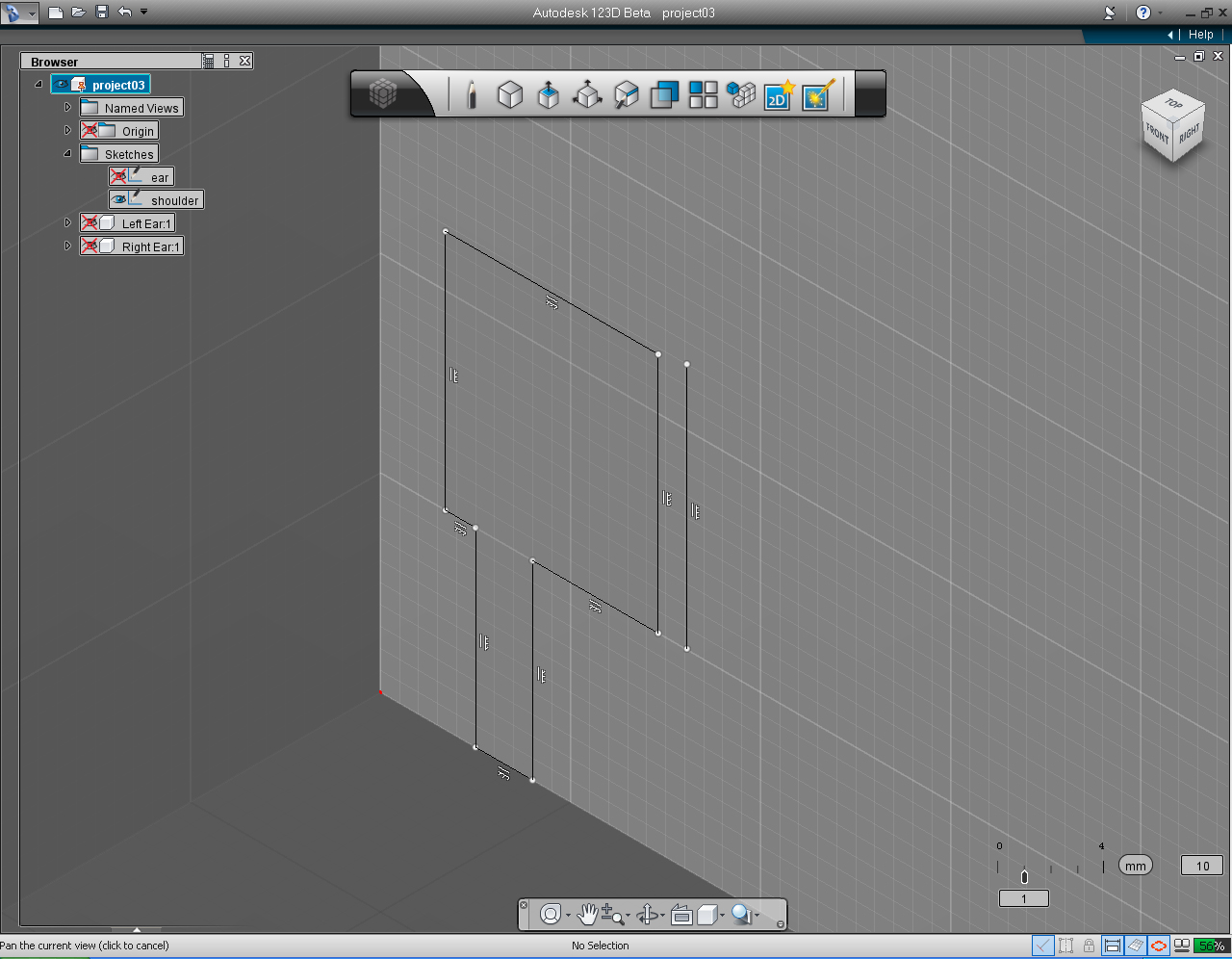
23. Use "Pan" function from "Navigation" Tool Menu to reposition the drawing in the middle of the screen.
24. Use mouse "Scroll" wheel (middle mouse button) to scroll drawing closer.
25. Select "Revolve" pill from "Create" Marking Menu.
26. Select the profile when 123D asks for it, and select the axis of revolution. (Note: We did this command before in creating ear steps.)
27. Click at drop down arrow next to keyboard input box, and Select "Full" function from the list.
28. Right click mouse buttom to bring up Marking Menu. Then click "OK" to commit the command.
29. Here we are, the incomplete shoulder. We are going to do some more editing to complete the shoulder solid model. Save the file!
Create Shoulders: Part 2 - Join Parts
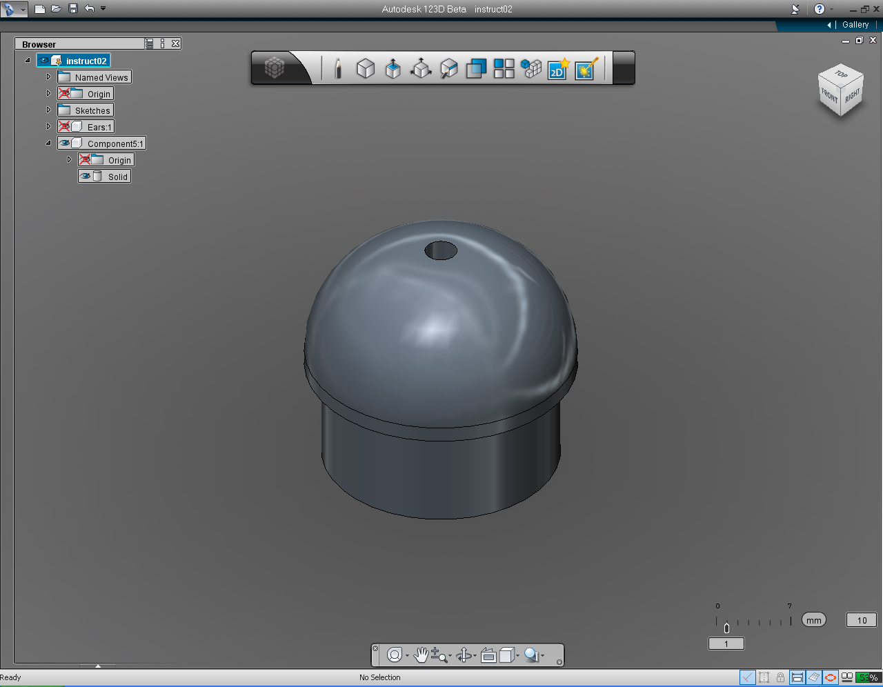
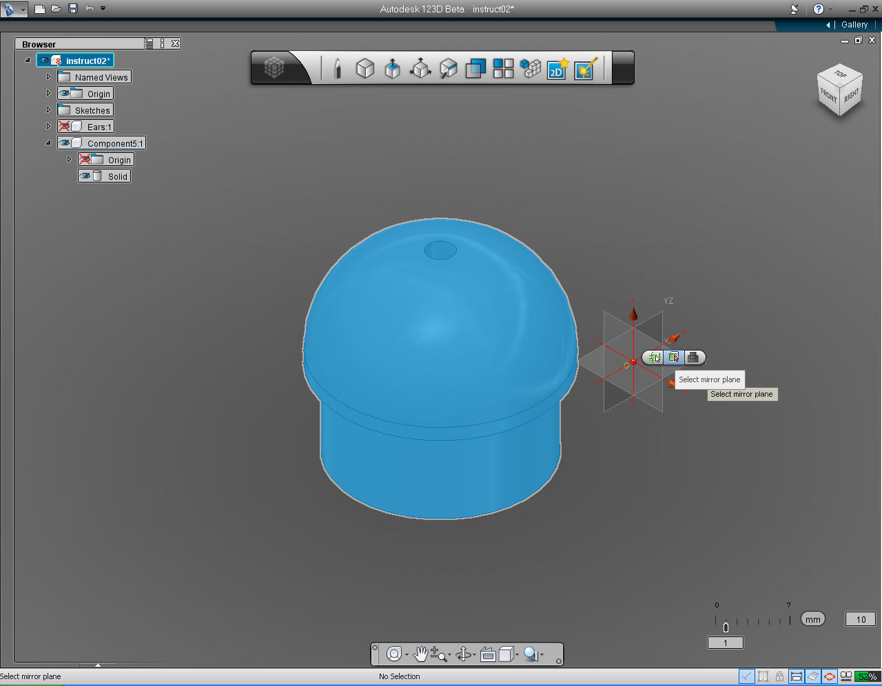
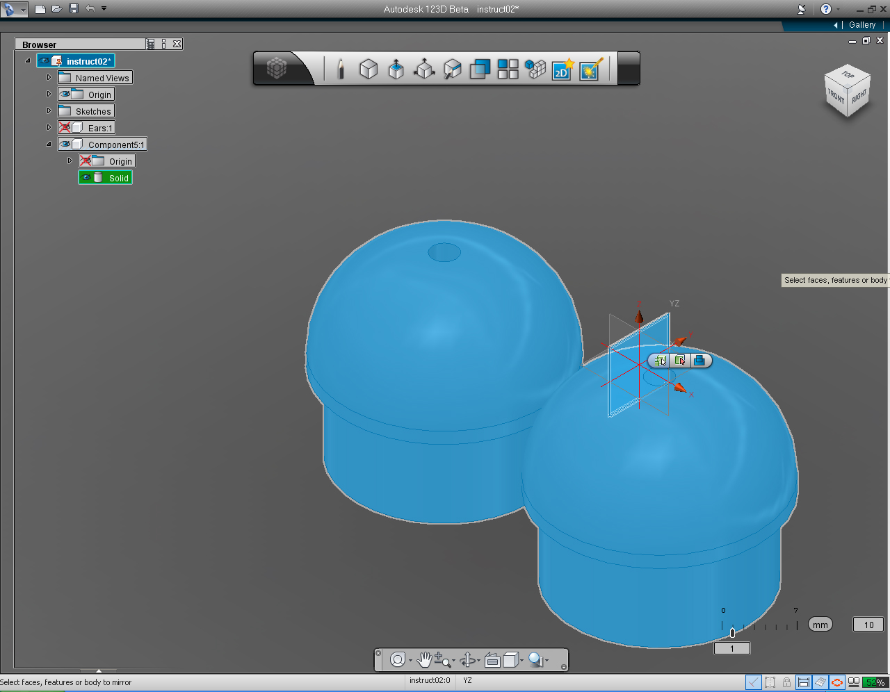
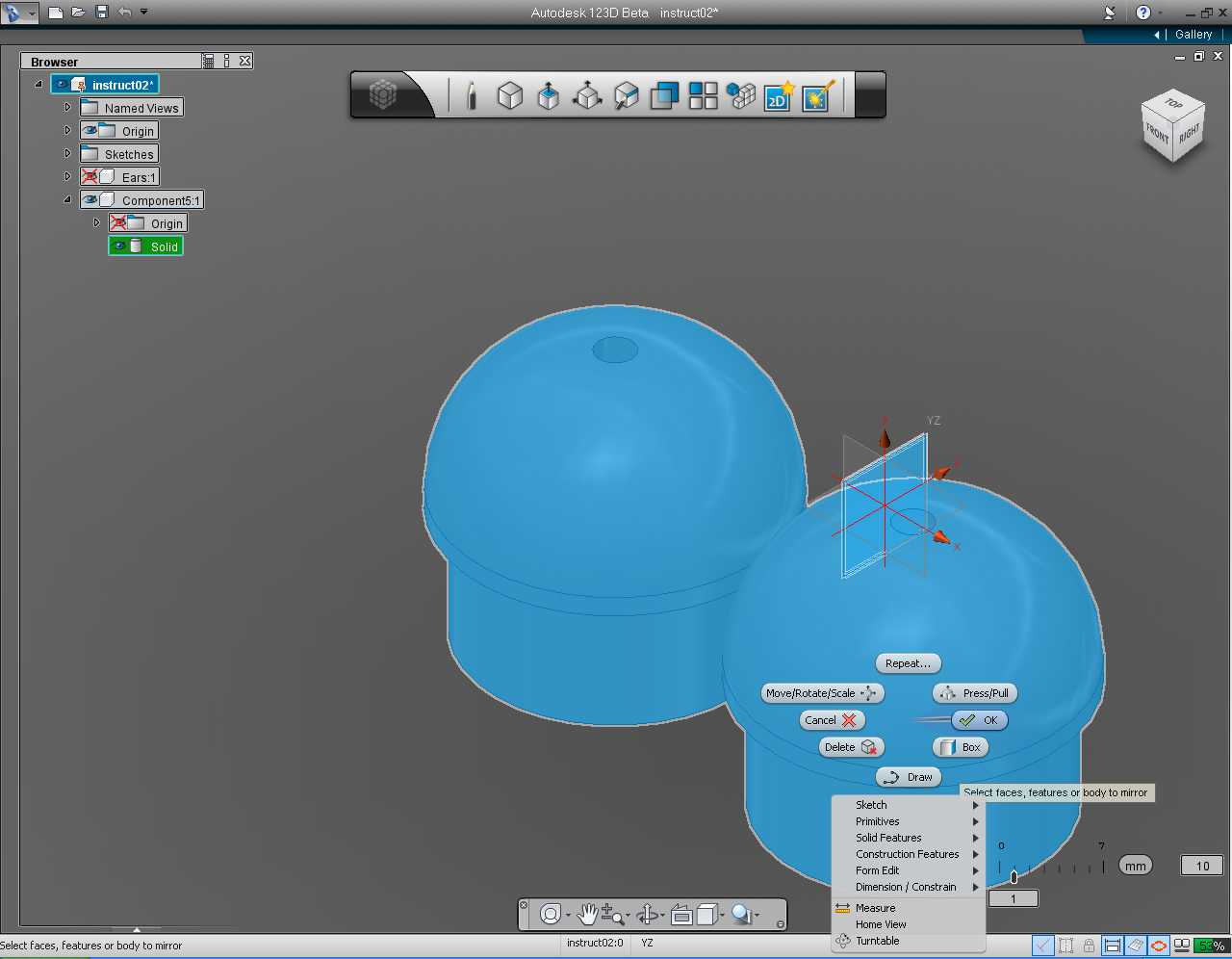
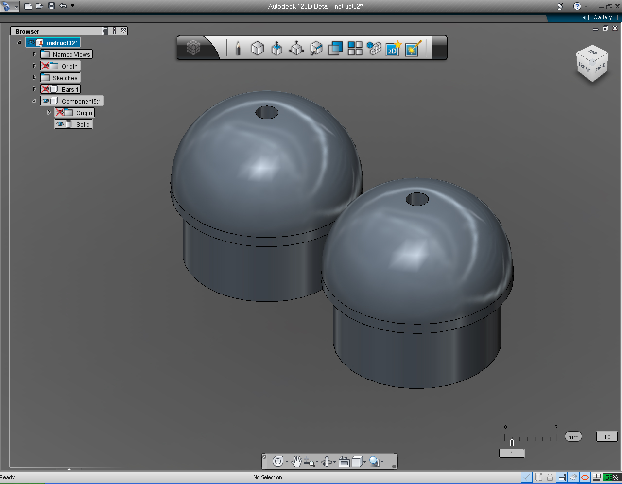
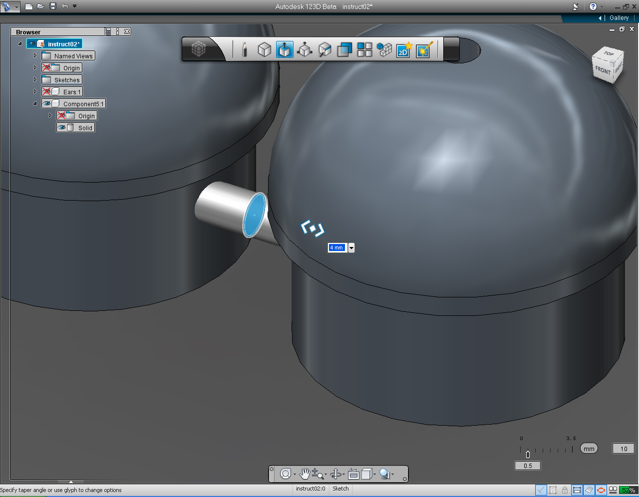
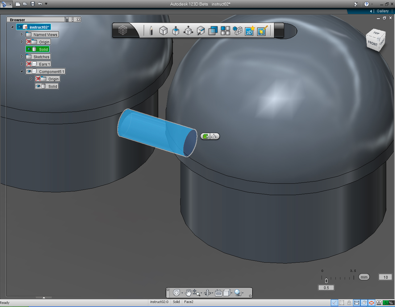
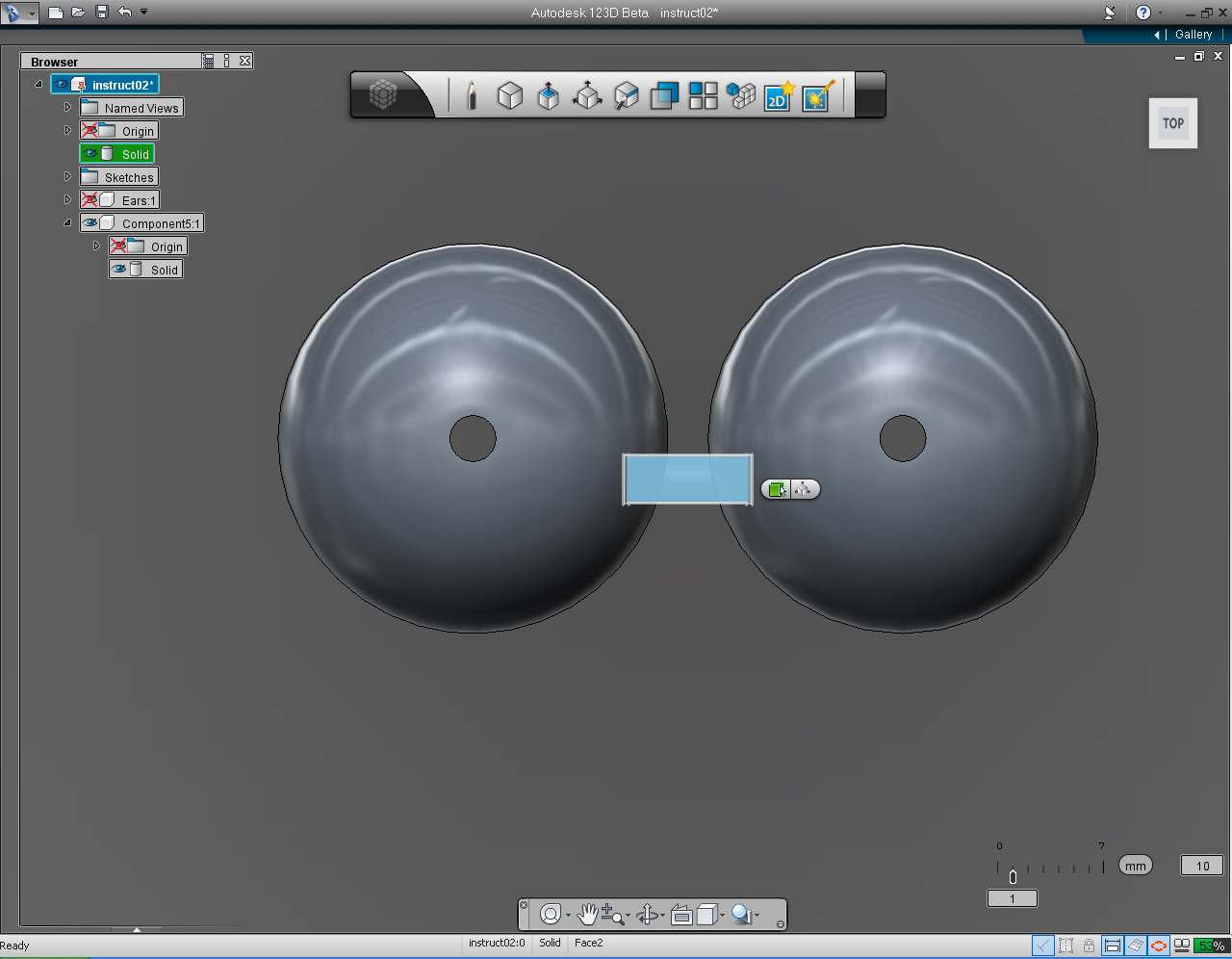
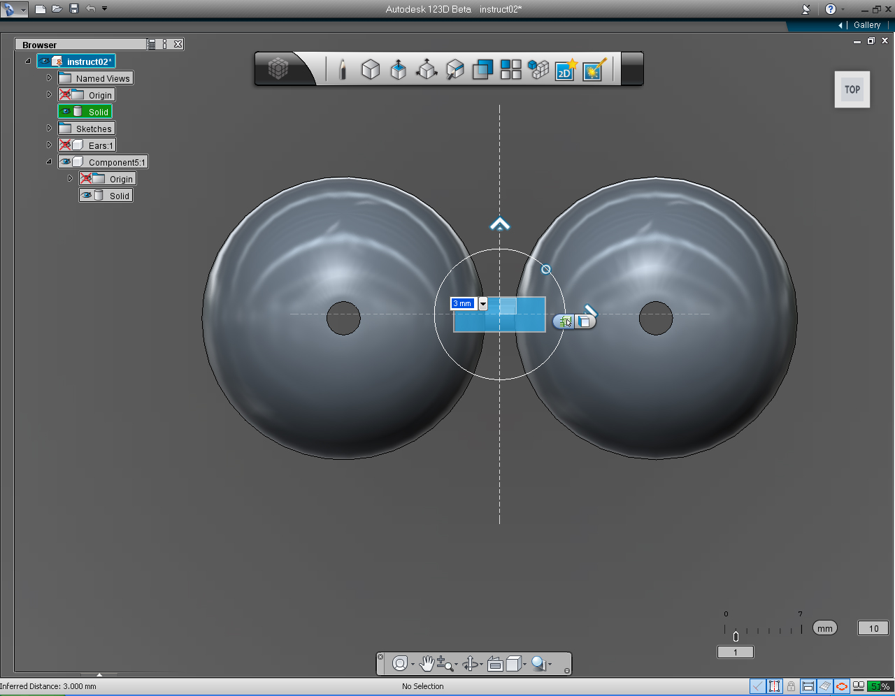
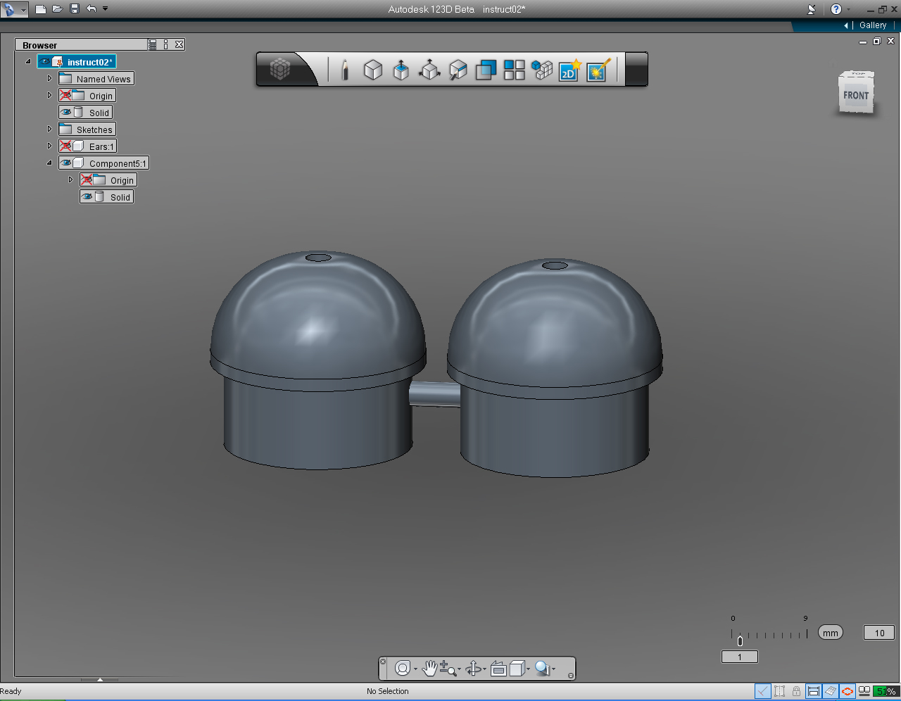
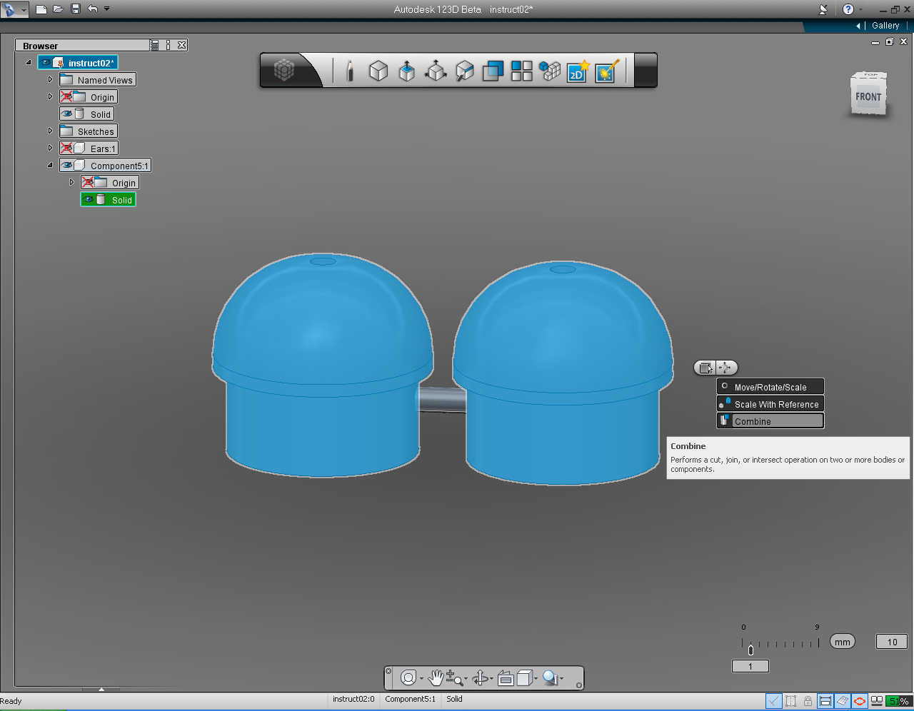
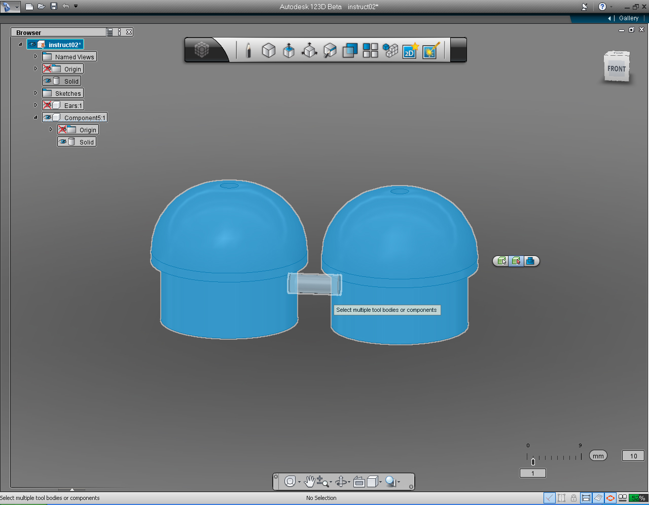
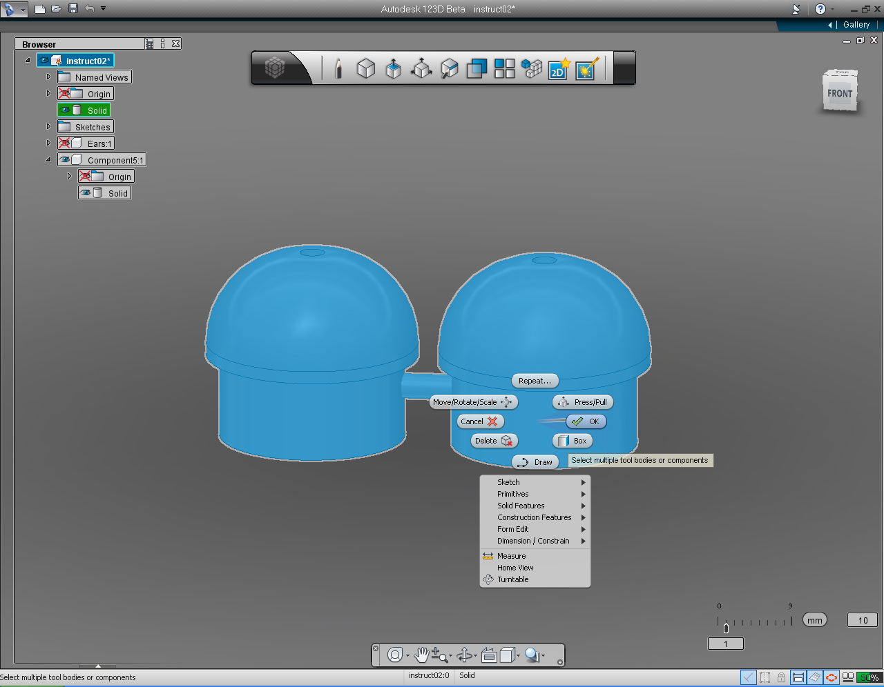
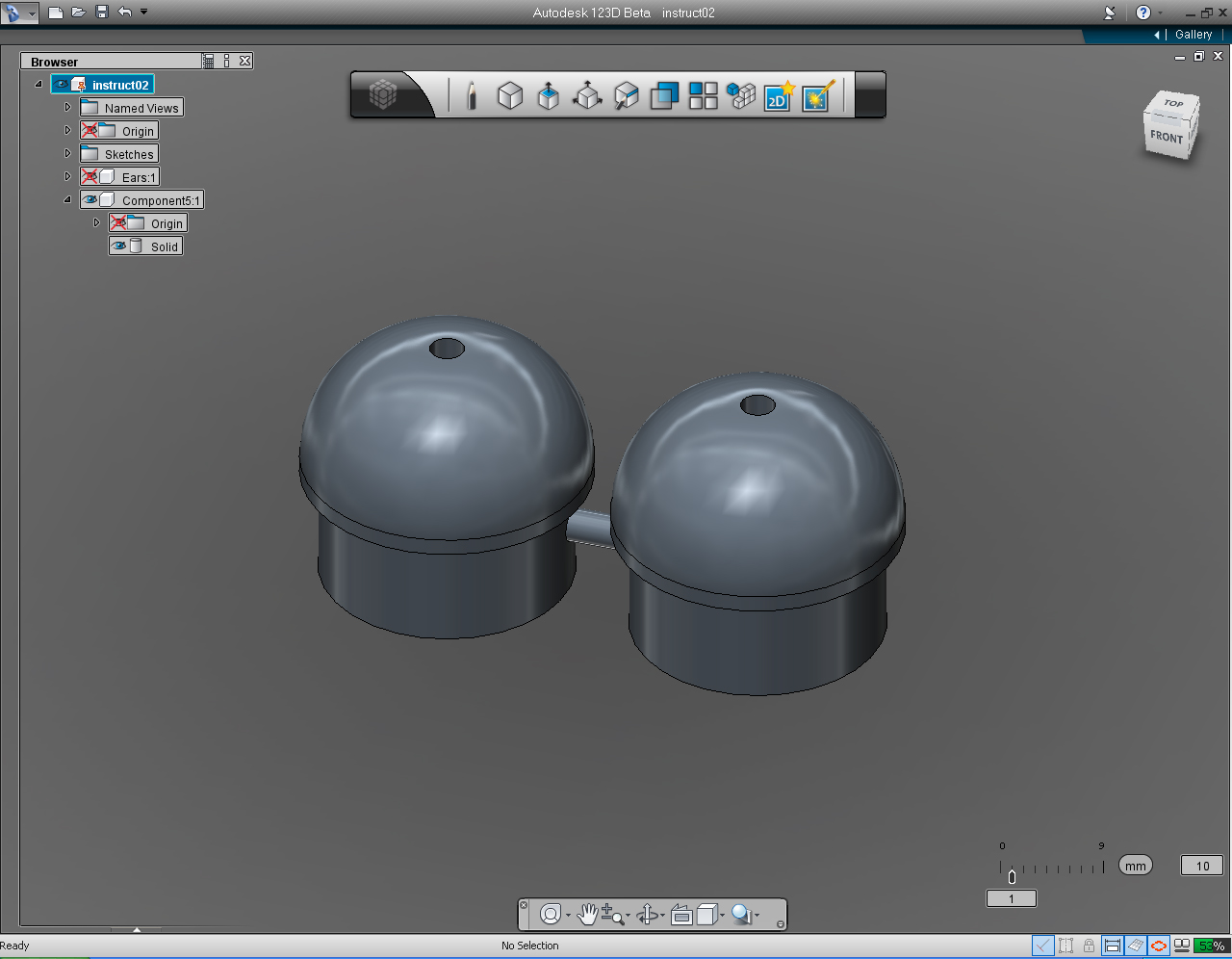
- "Fillet" pill in "Create" tool in Main Tool Bar.
- "Move/Rotate/Scale" pill menu
- "Mirror" function in the "Pattern" Marking Menu
- "Circle" pill in "Sketch" tool in Main Tool Bar.
- "Extrude" pill in "Create" tool in Main Tool Bar.
- "Symmetric" in "FreeForm" tool in Main Tool bar or in "Extrude" submenu
- "Combine" pill in "Create" tool in Main Tool Bar
And these are the steps:
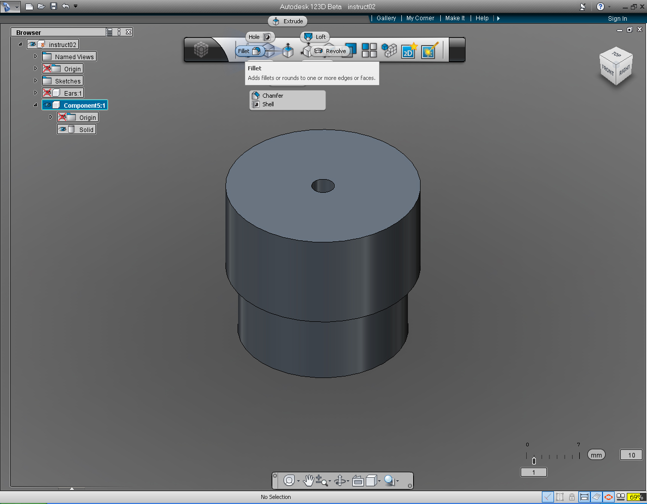
1. Repeat Step 6 to- Add solid model to a browser as Left Shoulder
- Make a copy of a shoulder add a solid model to a browser
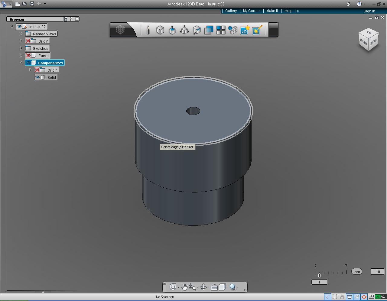
3. Select the top edge of the solid model.
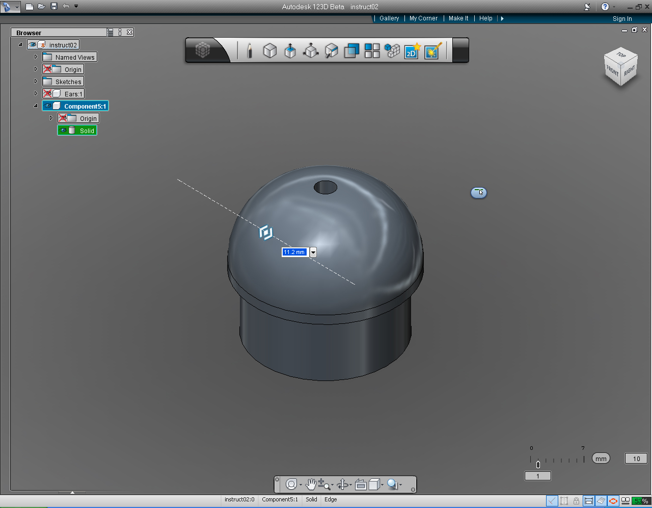
4. Specify the fillet radius, by drag the bi-direction arrow or use keyboard input to the amount of 11.2
5. Select "TOP" View on the "View Cube"
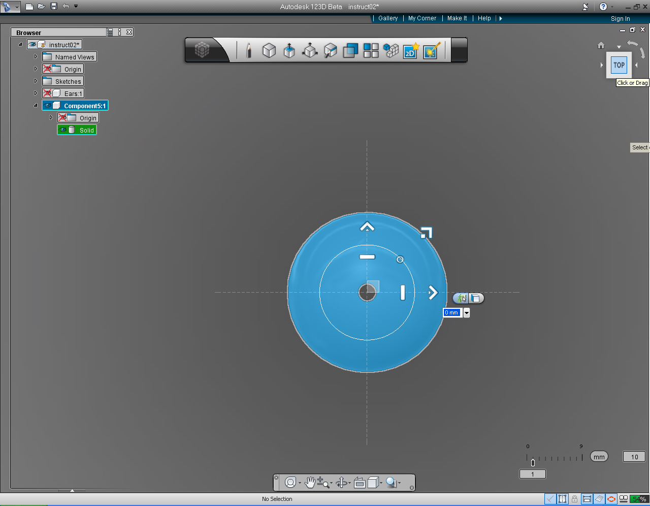
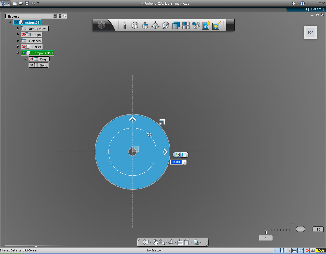
6. Right click at shoulder solid model to bring up the Marking Menu. Then select "Move/Rotate/Scale" pill.
7. Drag the the Right arrow to -14, or enter -14 in the input box.
8. Set the "View Cube" to Home.
9. Unhide the Coordinate Origin.
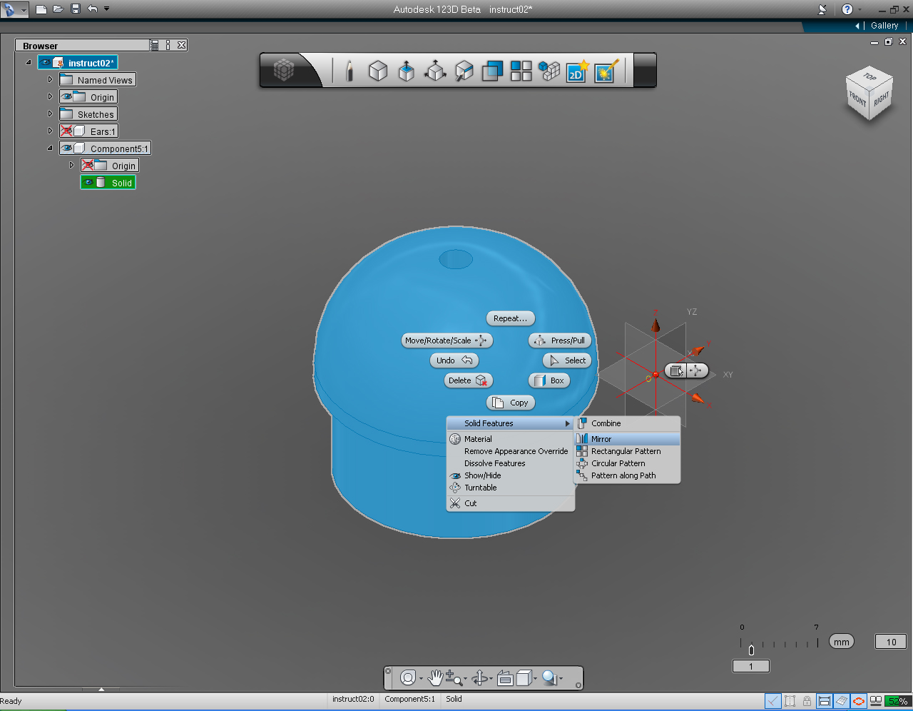
10. Right click at the solid model to bring up the Marking Menu. Then select "Mirror" in the "Solid Features" list.
11. Select YZ Plane on the Coordinate Origin to "Mirror" the shoulder.
12. Right click the mouse to bring up Marking Menu, and select "OK" to commit the command.
13. Now we got he complete left and right shoulders!
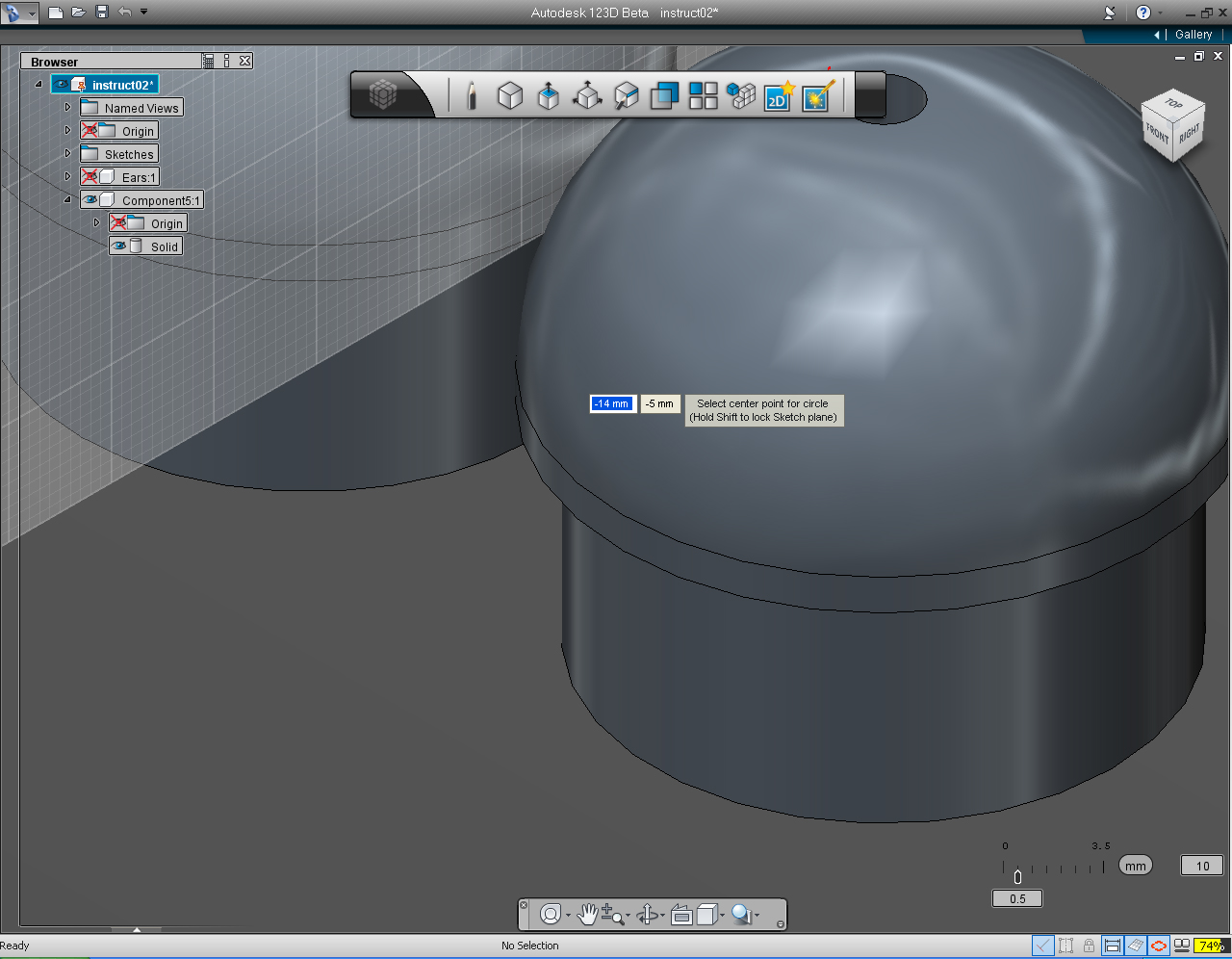
14. Start to draw the "Circle" on the "Right Plane", using the "Circle" pill from the "Sketch" Marking Menu.
15. Set the center of the circle to -14 and -5.
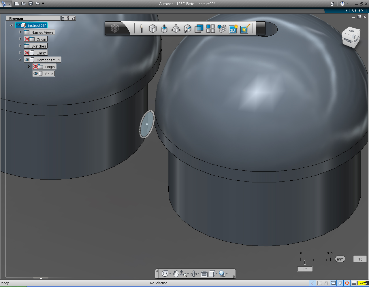
16. Assign the radius of the circle as 1.5mm
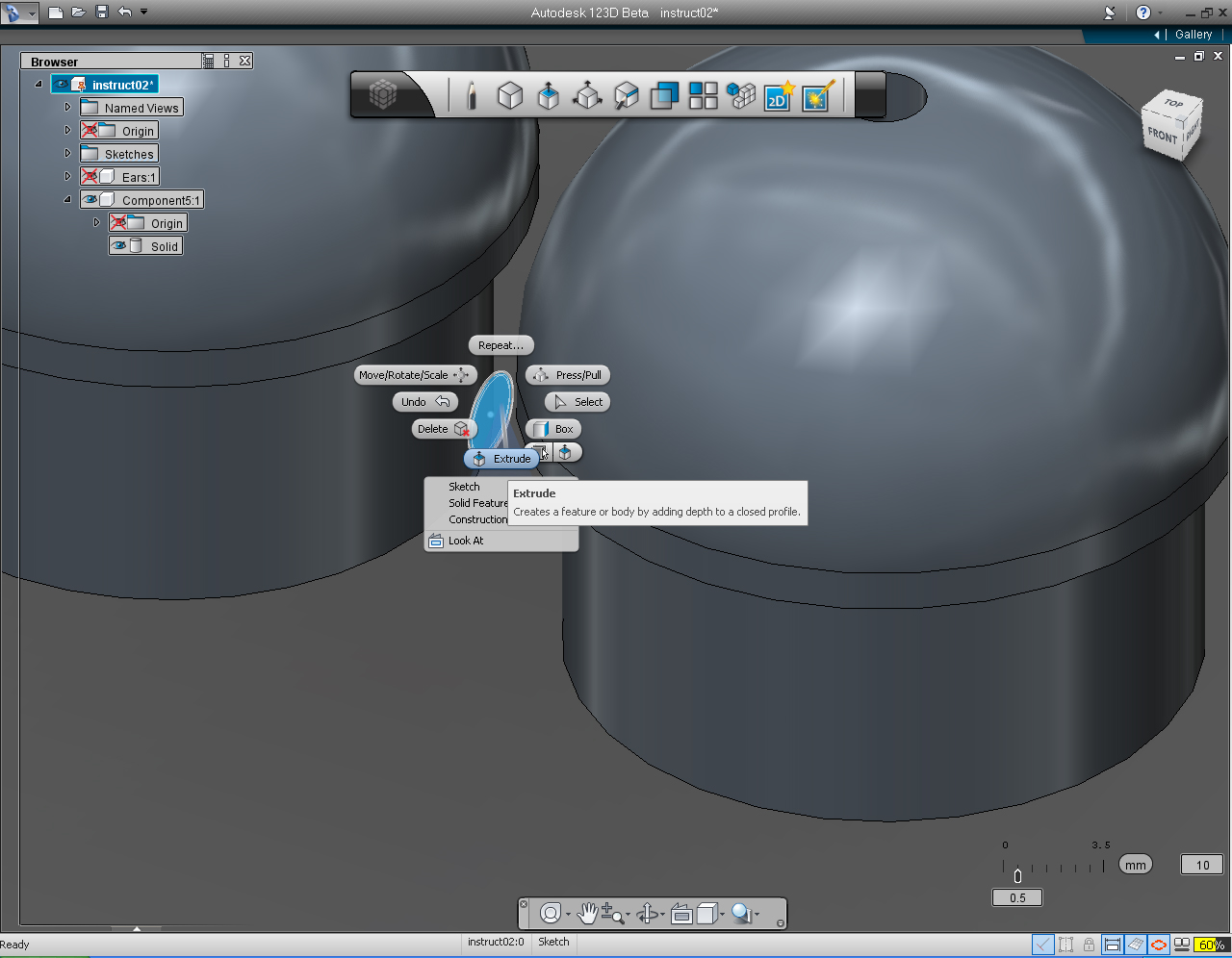
17. Select the circle that we just drawn. Right click at the circle to brign up Marking Menu, then select "Extrude" pill from the menu.
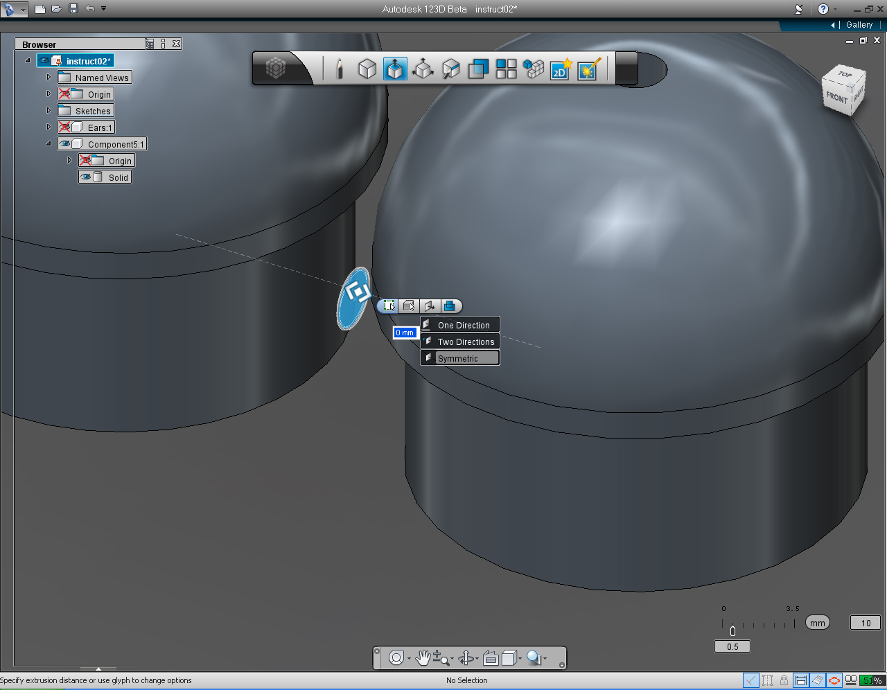
18. On the "Extrude" submenu, select the fourth or right most icon on the pill. Then select "Symmetric". This will extrude the circle in both direction.
19. Drag the bidirectional arrow (or use keyboard input) to 4.5 unit.
20. Right click to bring the Marking Menu, then select "OK" pill to commit the command.
21. Change "View Cube" to TOP Plane.
22. Right click the mouse to bring up the "Move/Rotate/Scale" Marking Menu. Then drag the up arrow to move the cylinder to approximately middle of the shoulder.
23. Rotate the "View Cube" to view the FRONT view.
24. Select the Solid model of shoulder component.
25. Right click on the shoulder solid model to bring up Marking Menu. Then select "Combine" from the list.
26. Select the cylinder, to combine to shoulder solid model.
27. Right click mouse to bring up Marking Menu, Then Click "OK" to commit command.
28. Now we got both shoulders and an extruded solid circle "joined" together.
29. Rename the "Component" to "Shoulder"
After you're done with the shoulders, save the file.
And always save the file often, this can prevent you from starting over from scratch!
Further Study:
Autodesk 123D - Intro to Sketches Video Series: Multiple Sketches Part 1
Hands: Part 1- Fingers


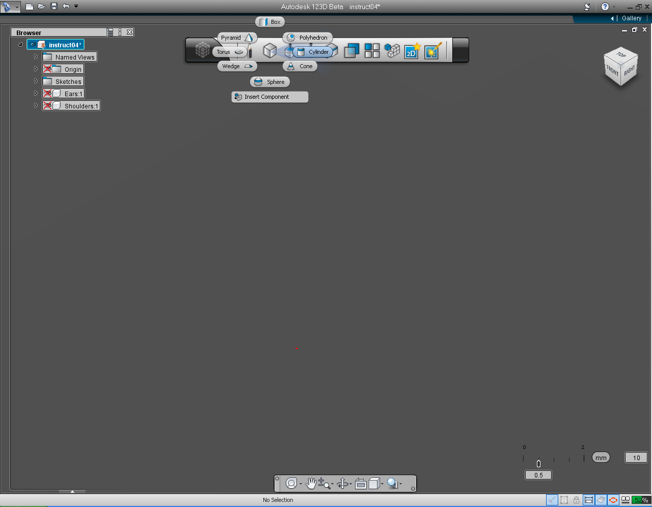
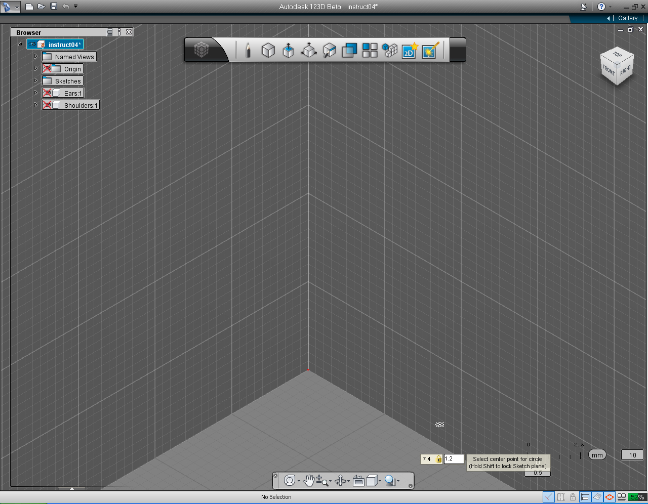
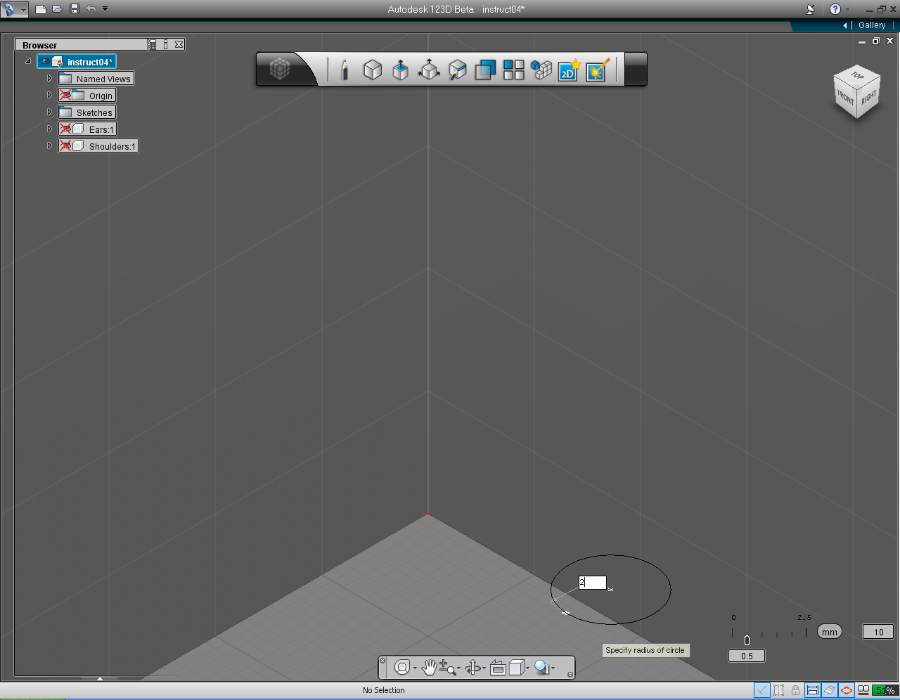
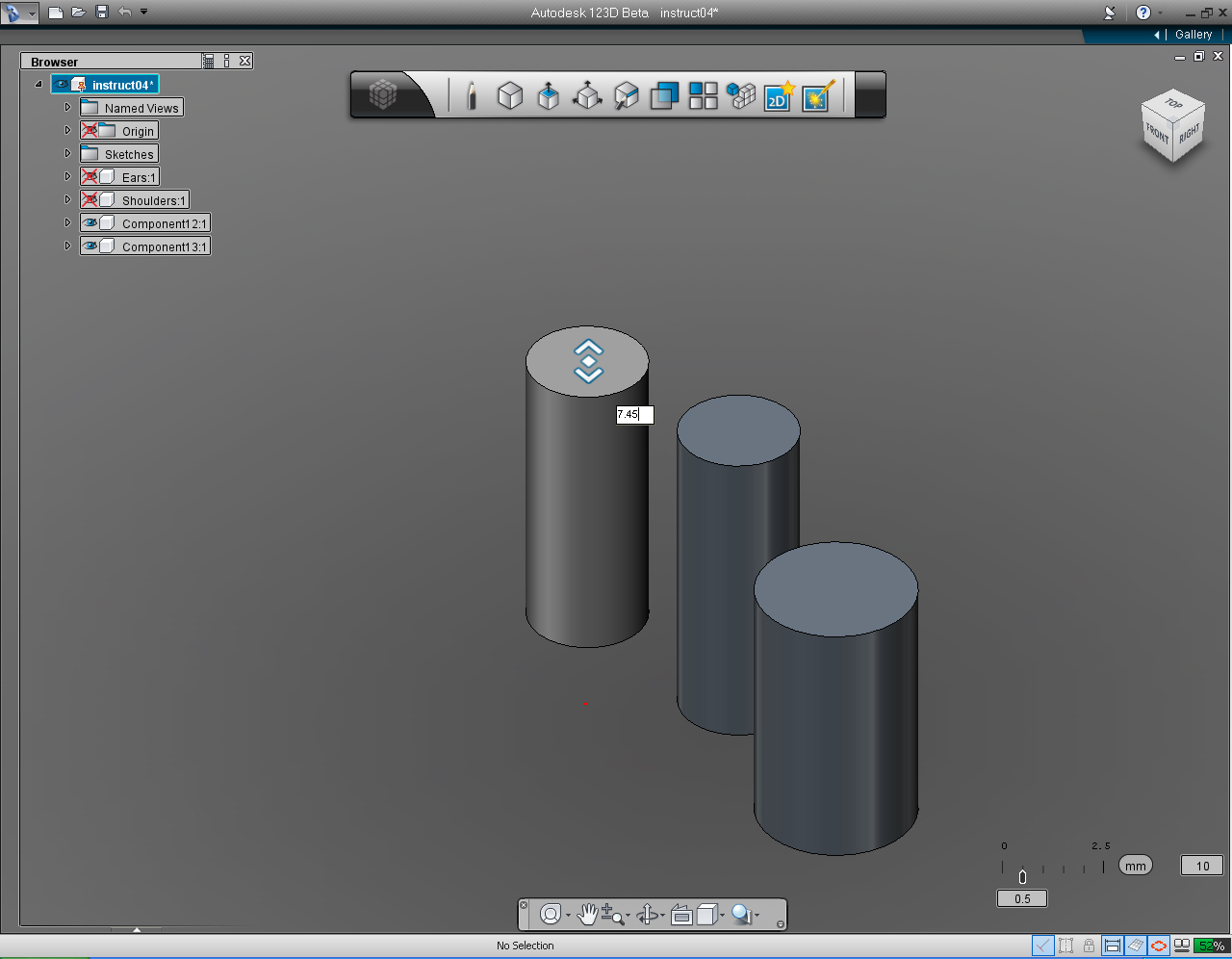
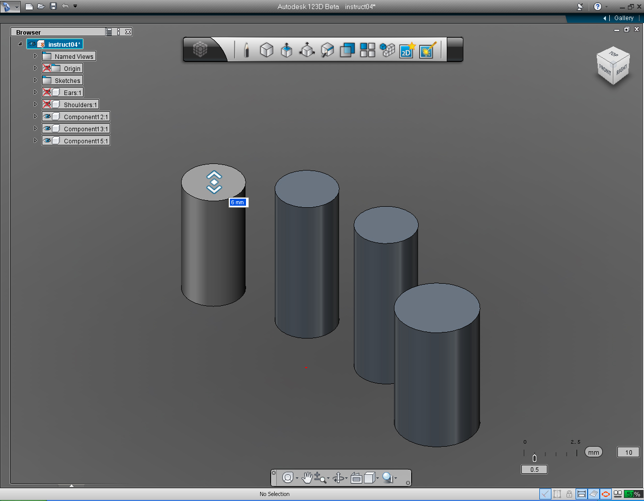
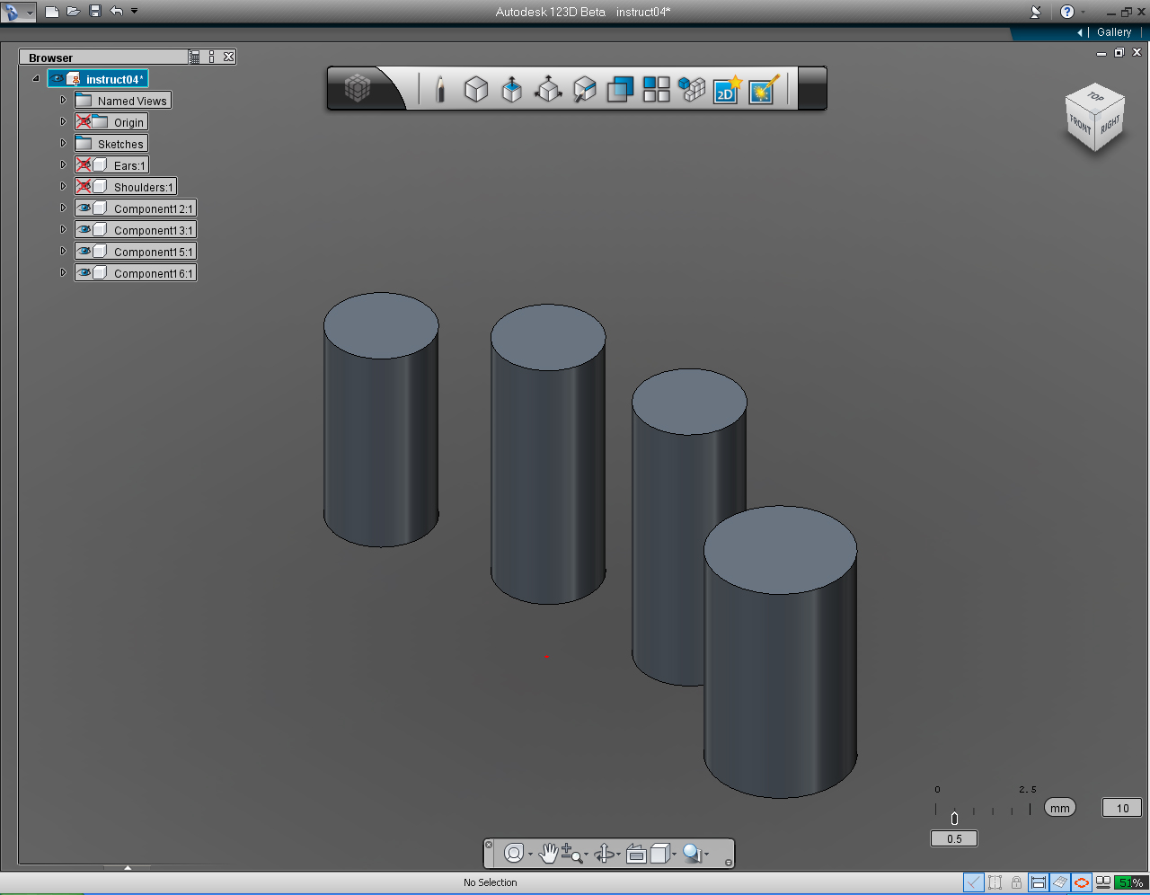
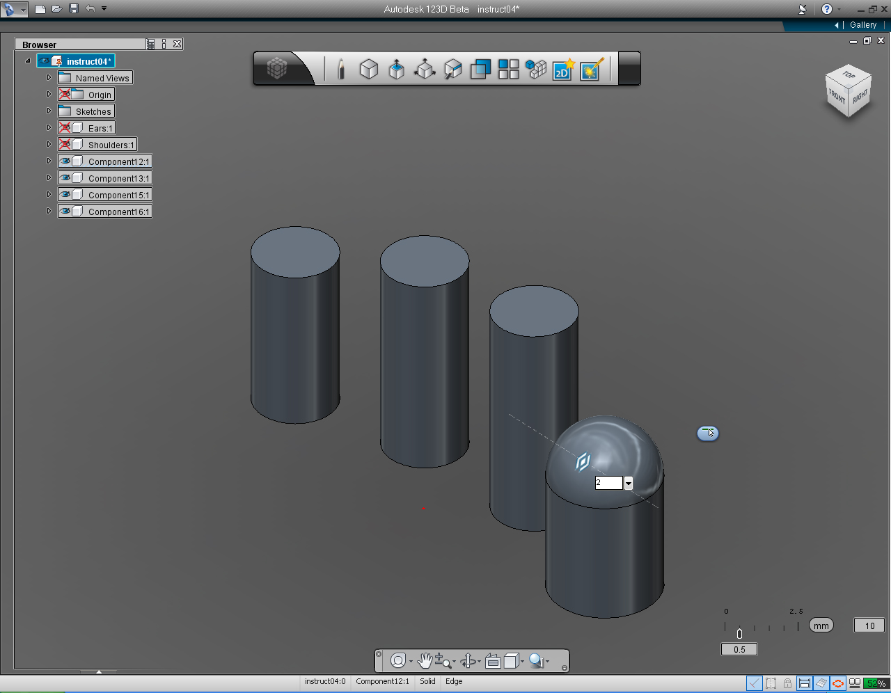
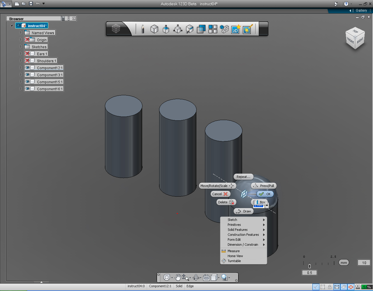
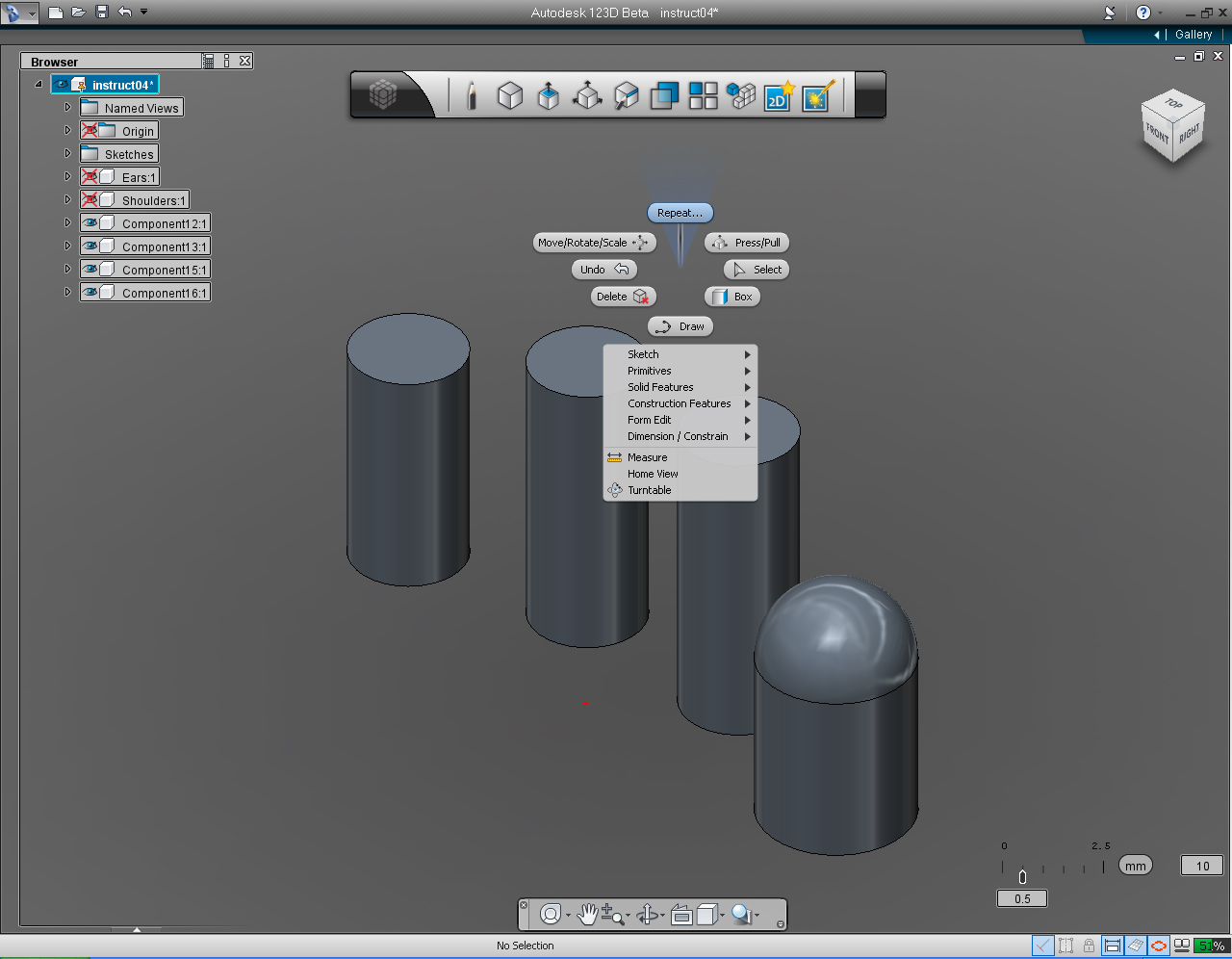
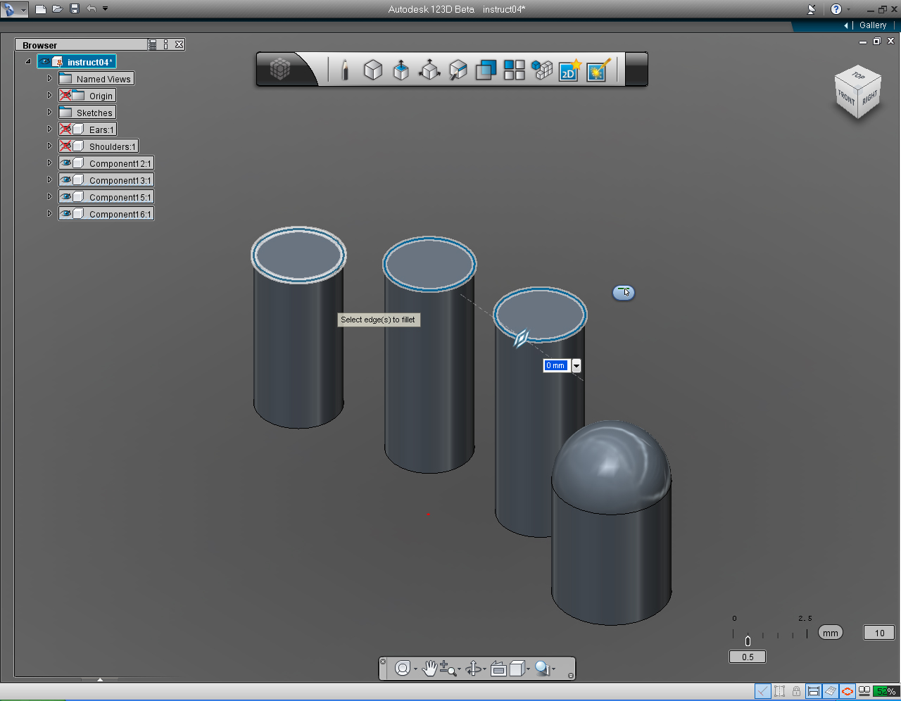
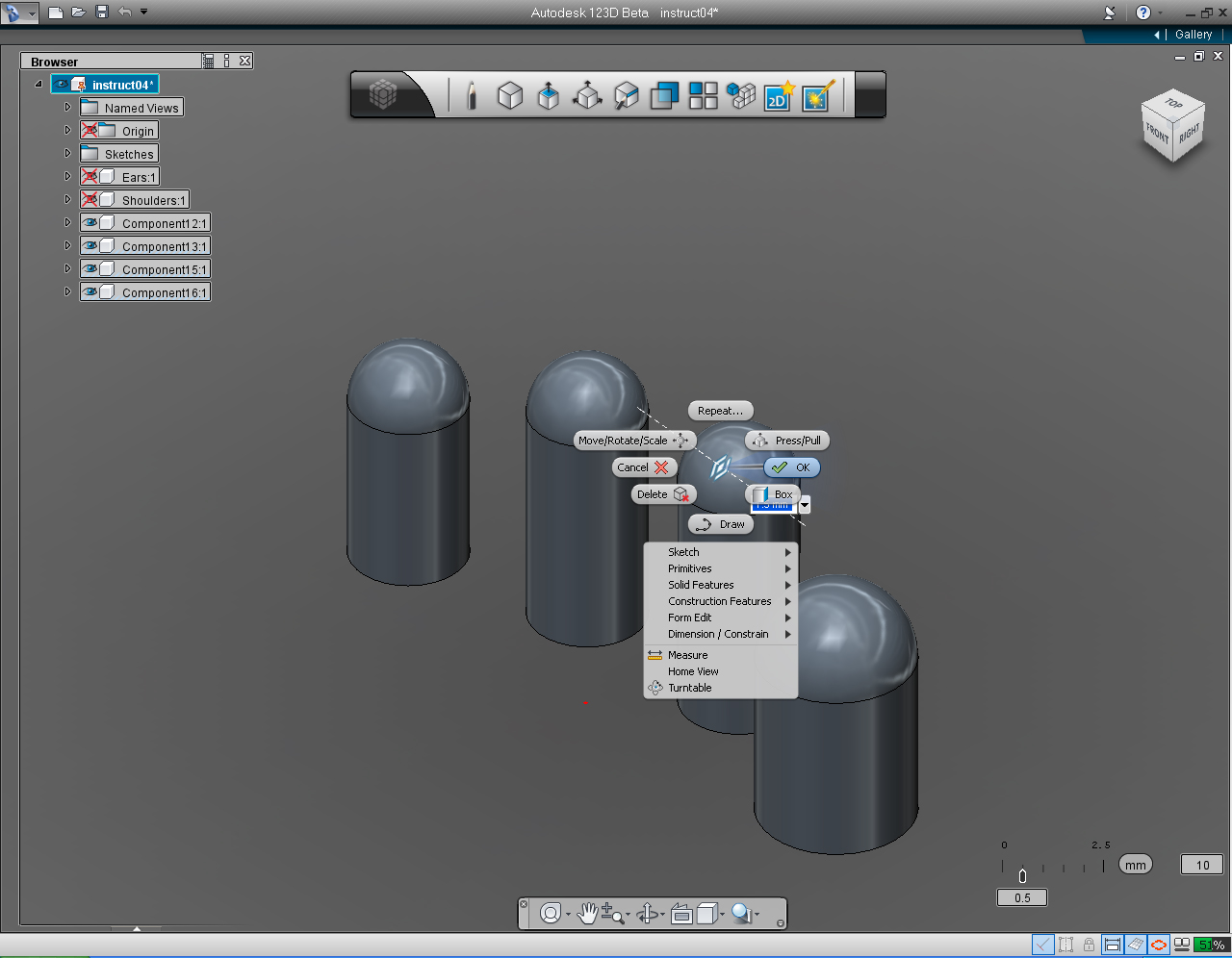
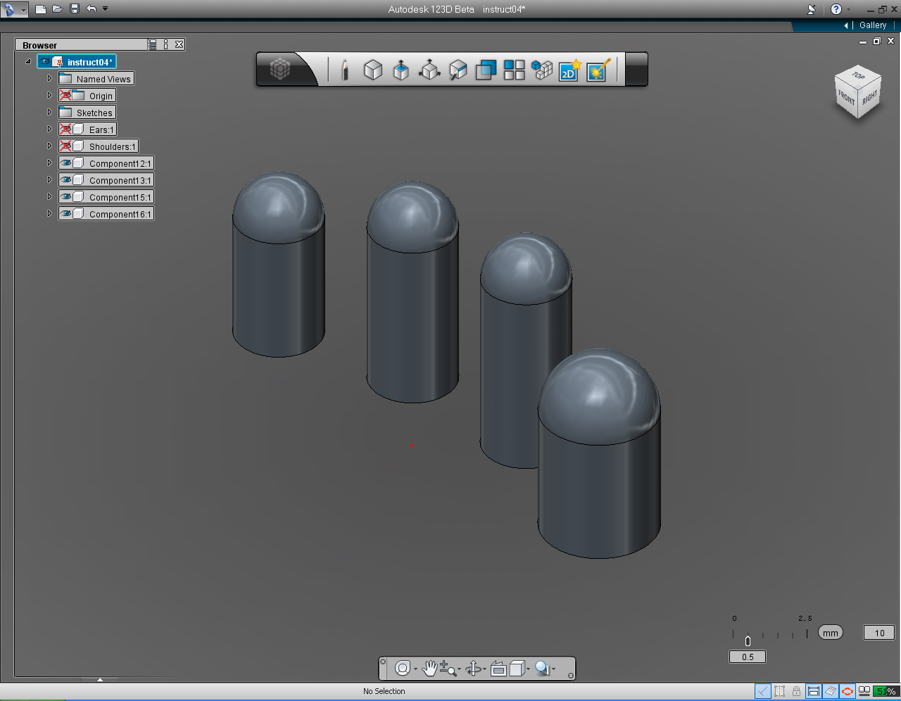
Alright, we are going to create 3D model of hands and fingers using different approach. This time we are going to create hand with four fingers, without going through the the process of lines drawing any more. A lot more fun! And we are going to do this in the "Orthogonal View" alone. No swapping view around either!
Let's plan ahead of how we are going to create an hand, using the available cross-section.
On the cross-section sketch sheet, we can only see that there is a profile of the finger. with no locations or coordinates of any finger found. That is not the problem, because I have the information of these four (Yes, four. Because It's the robot!) fingers as follow:
Thumb:
Also the cross-section of the hand indicates that there are three circle with the radius of 8.1125 (The void area inside the hand), the OD (Outside Diameter) circle with the radius of 12.7mm, and the ID (Inside Diameter) circle of the hand has the radius of 11.1125mm. These info. are adequate to build the hand.
- We are going to create all the fingers on the top plane first. Using "Cylinder" function in the "Primitive" Marking Menu or bucket.
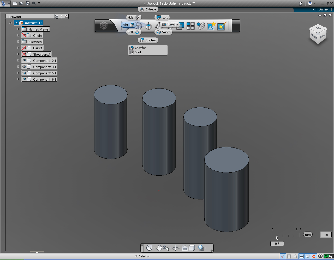
- Then "Extrude" them up to their height. And "Fillet" the top end of those fingers.
- Next, we will use "Create" tool in Main Tool Bar to create two "Cylinder" and assign the thickness of the palm and wrist.
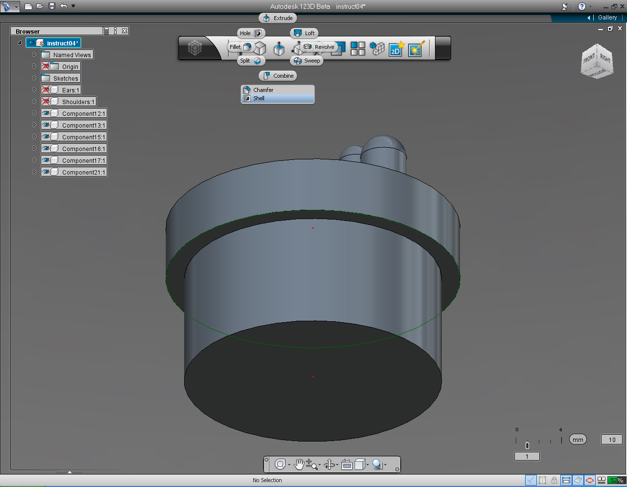
- Then use the "Shell" function in the "Create" bucket to create the void area in the wrist.
- Add use "Combine" function in the "Create" bucket to combine all the fingers, palm and wrist together as one single hand.
- Make a copy of hand and add a solid model to a browser.
And these are the steps:
1. Rendering of the hand 3D model that we are creating.
2. Cross-section of the hand, with dimension to be drawn in 123D.
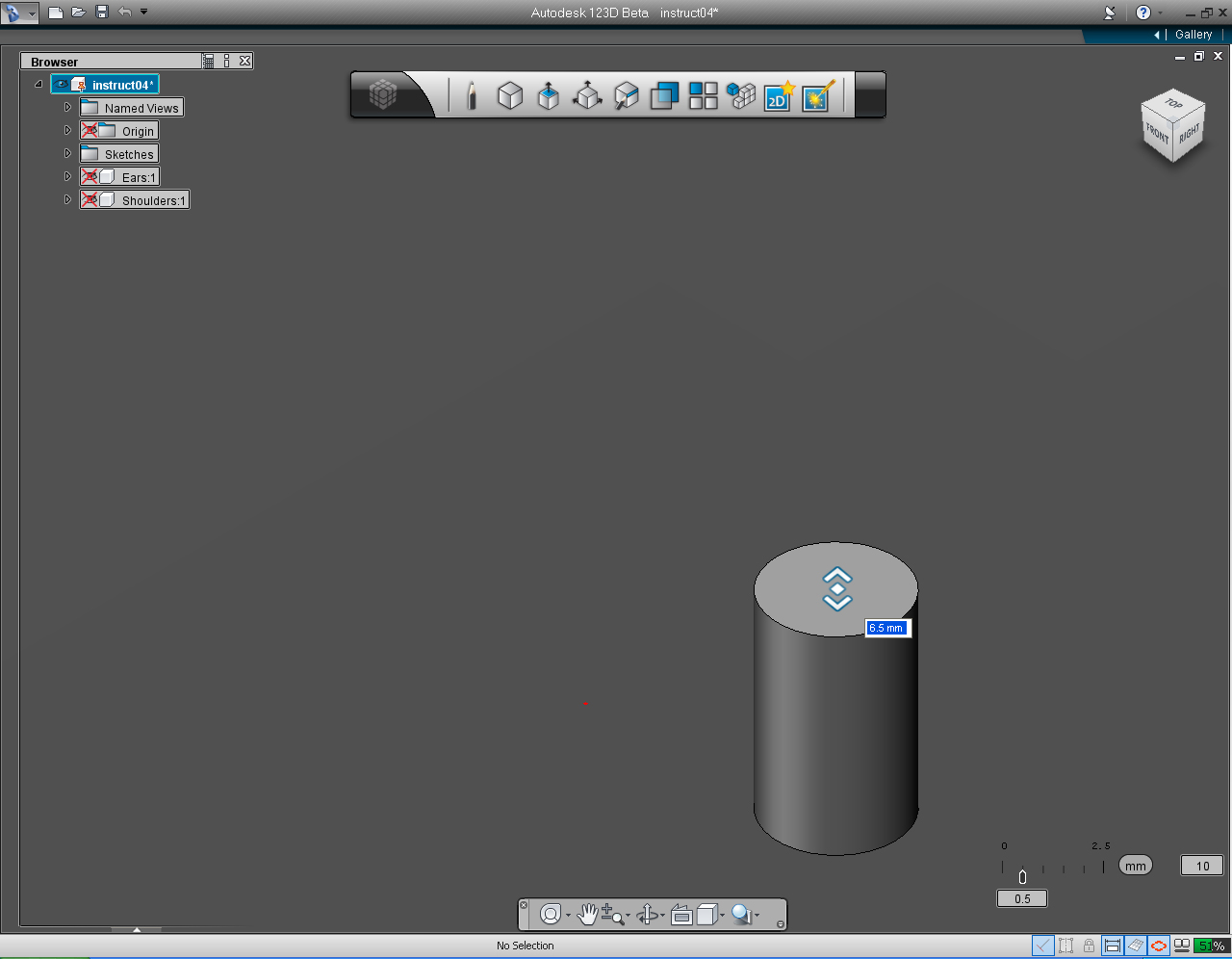
3. To draw the thumb, select "Cylinder" pill in the "Primitive" Marking Menu
4. Set center point of the cylinder at 7.4 and 1.2
5. Assign the radius of the circle as 2mm.
6. Drag the bi-directional arrow up to specify the height of the thumb as 6.45mm
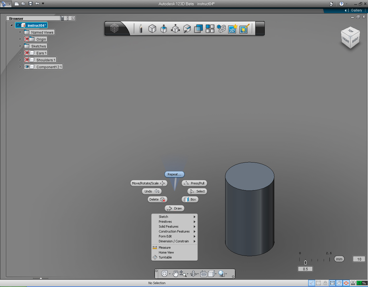
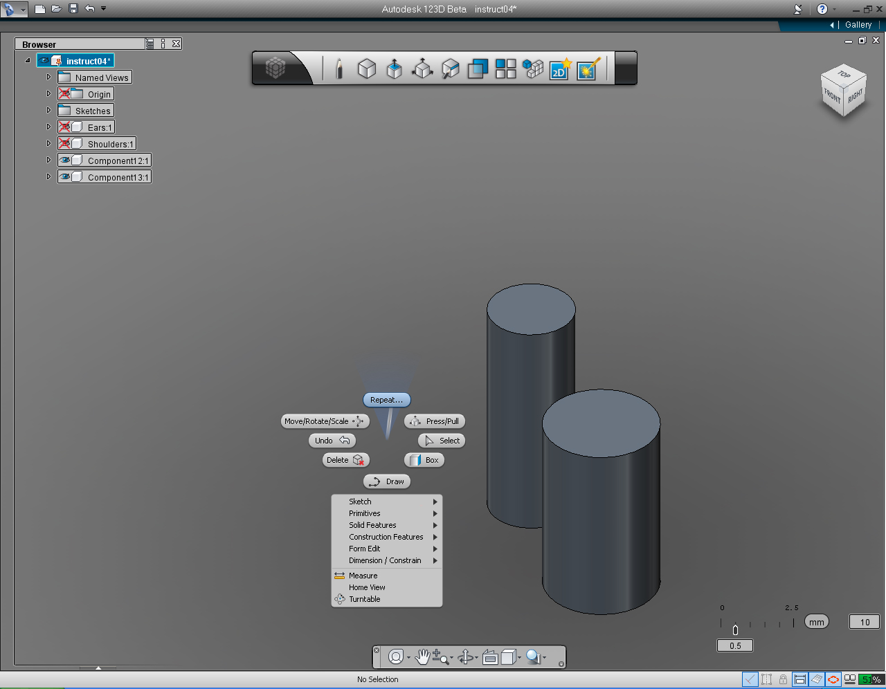
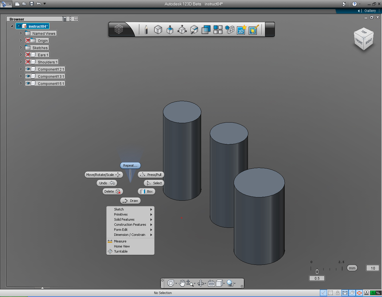
7. Right click the mouse to bring up the Marking Menu, then select "Repeat.." pill to draw the new cylinder, the First finger.
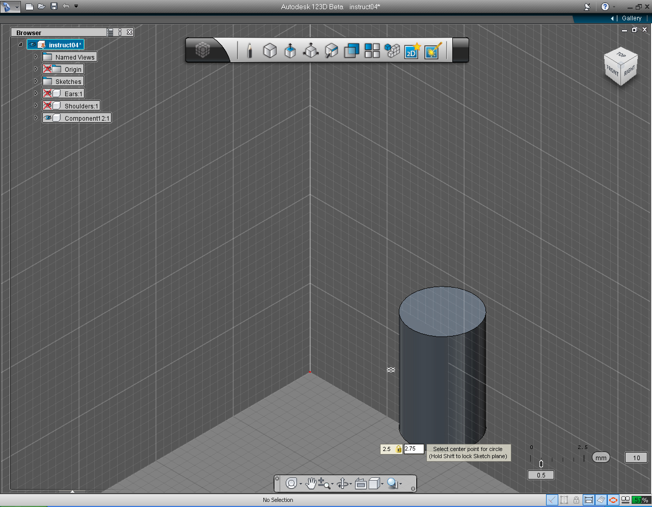
8. Set the center point of the cylinder to 2.5 and 2.75
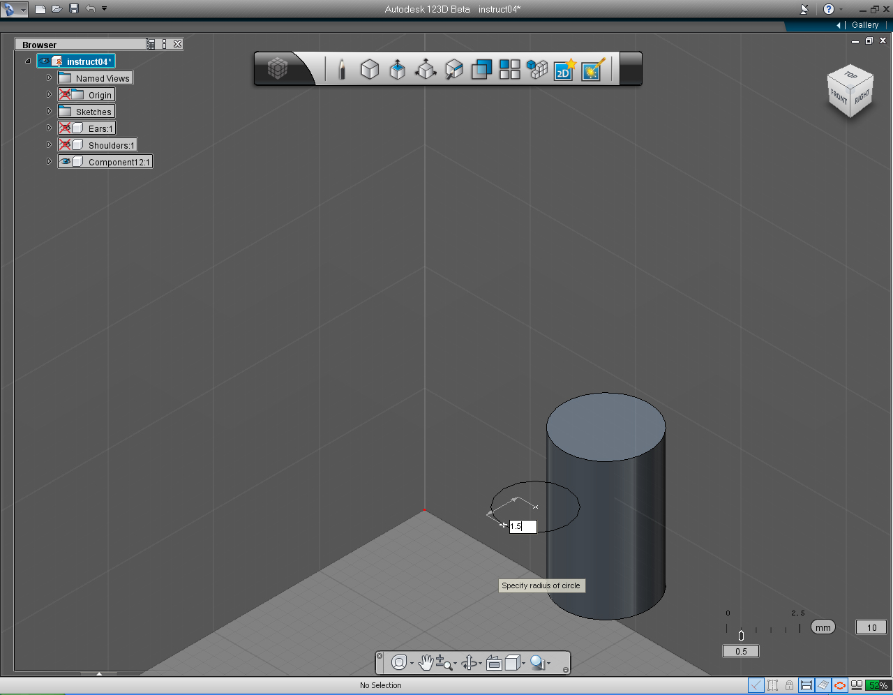
9. Specify the radius of the First finger to 1.5mm
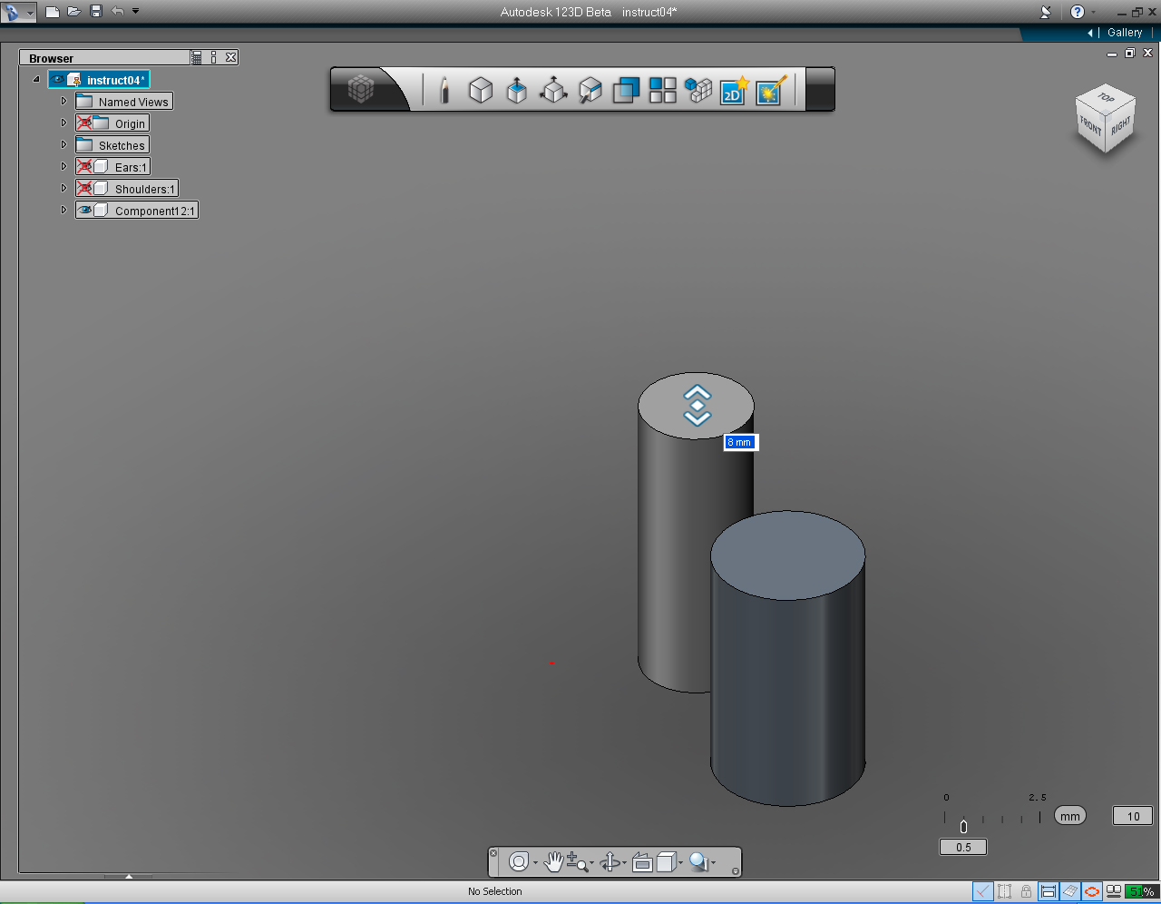
10. Drag the bi-directional arrow to set the height of the First finger to 8mm
11. "Repeat.." the command again to draw the new cylinder, the Second finger.
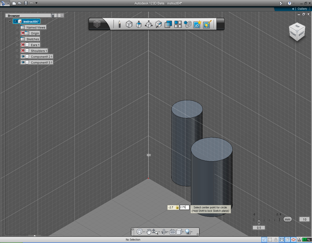
12. Set the center point of the cylinder to -2.7 and 2.75
13. Set the radius to 1.5mm
14. Drag the bi-directional arrow up to specify the height of the thumb as 7.5mm
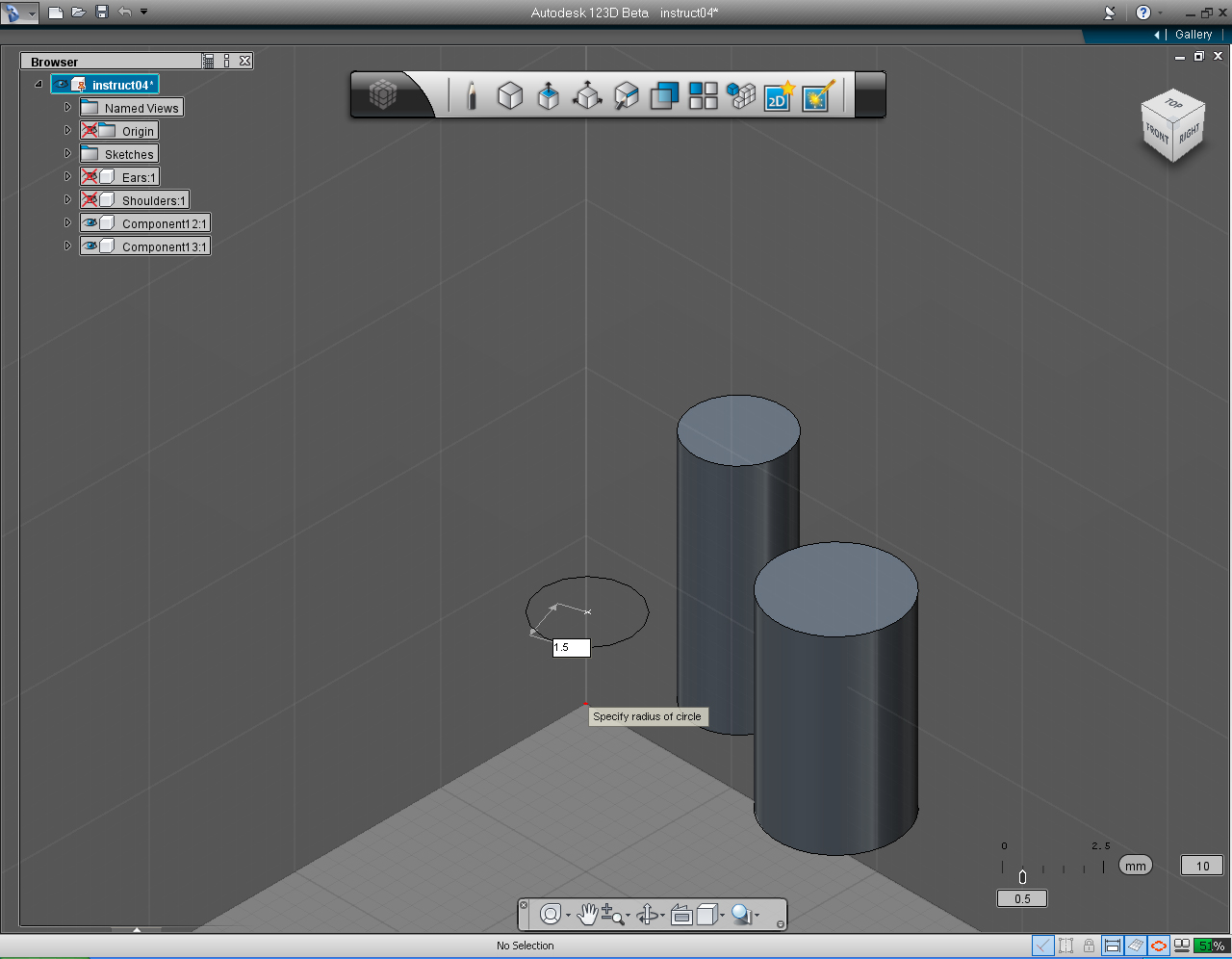
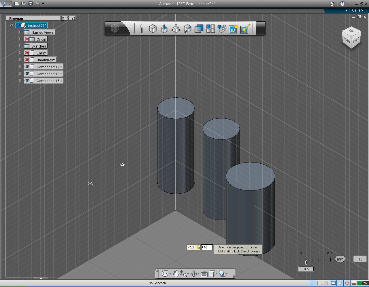
15. "Repeat.." the command again to draw the new cylinder, the Third finger.
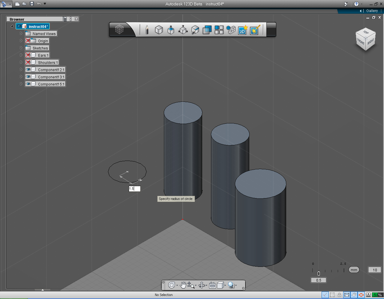
16. Set the center point of the cylinder to -7.6 and 1.5
17. Set the radius to 1.5mm
18. Drag the bi-directional arrow up to specify the height of the thumb as 6mm
19. These are the new components for the fingers.
20. Next we are going to "Fillet" the fingers to have the round ends. Select the "Fillet" pill from the "Create" Marking Menu
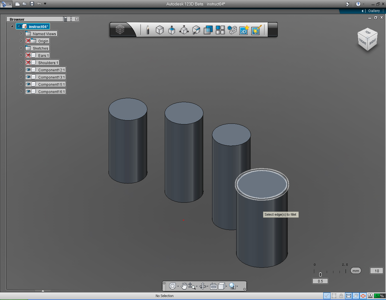
21. Select the top edge of the Thumb.
22. Drag the bi-directional arrow to specify the fillet radius to 2mm
23. Right click to bring up Marking Menu, then select "OK" pill to commit the command.
24. Right click to bring up Marking Menu, then select "Repeat.." pill to "fillet" all the rest of the finger.
25. Select the top edge of the First, Second and Third fingers.Then specify the fillet radius to 1.5mm, either by dragging the bi-directional arrow, or input the value using keyboard.
26. Commit the command by right click the mouse and select "OK"
27. Now we got the fingers done!
Further Study:
Autodesk 123D - Intro to Sketches Video Series: Multiple Sketches Part 2
123D Tips Video Series by 123d:Tip#9: Using the Mirror Function to Copy Objects
Hands: Part 2 - Palm and Wrist
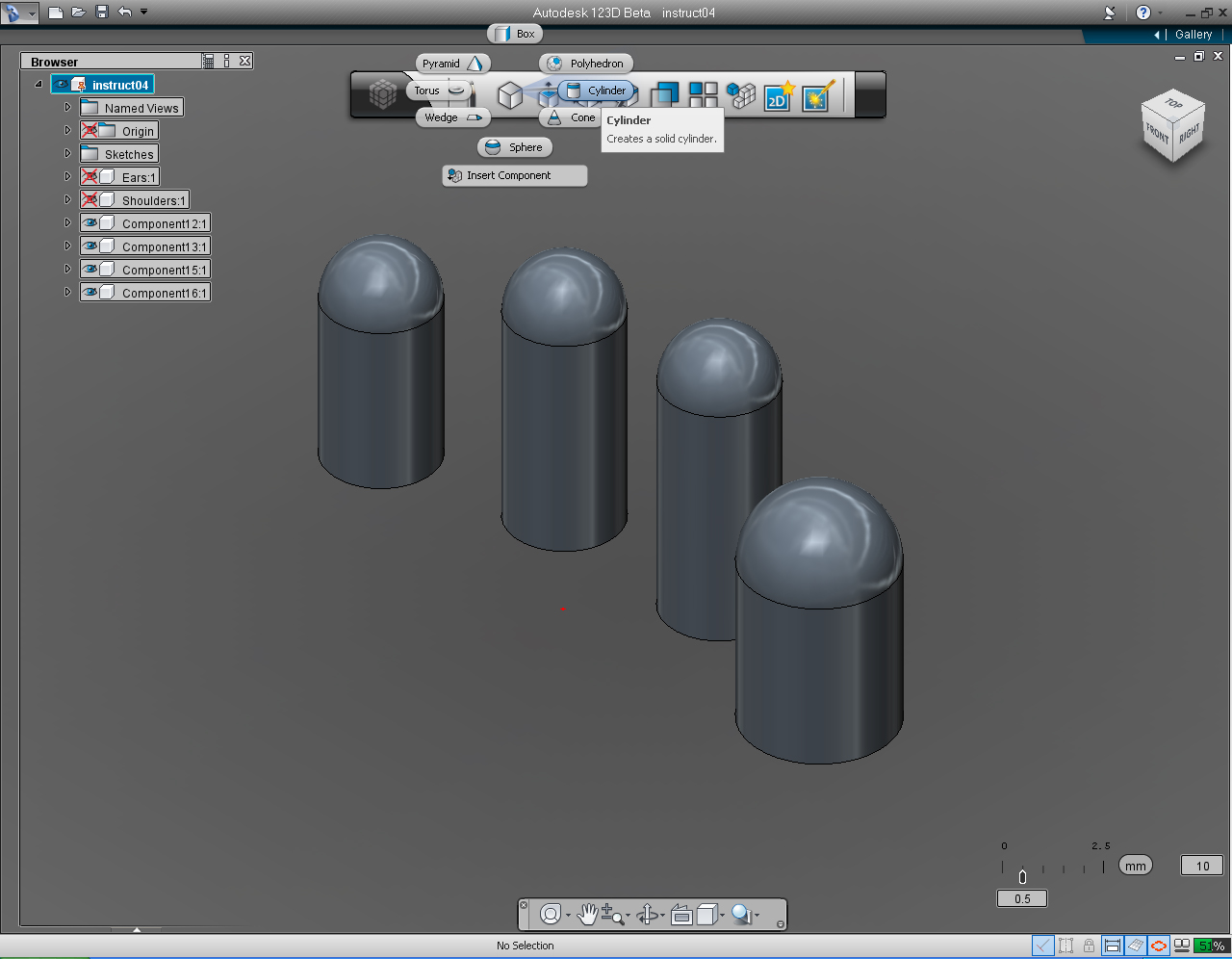
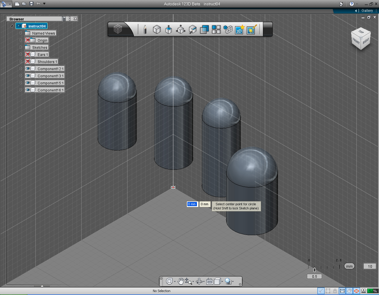
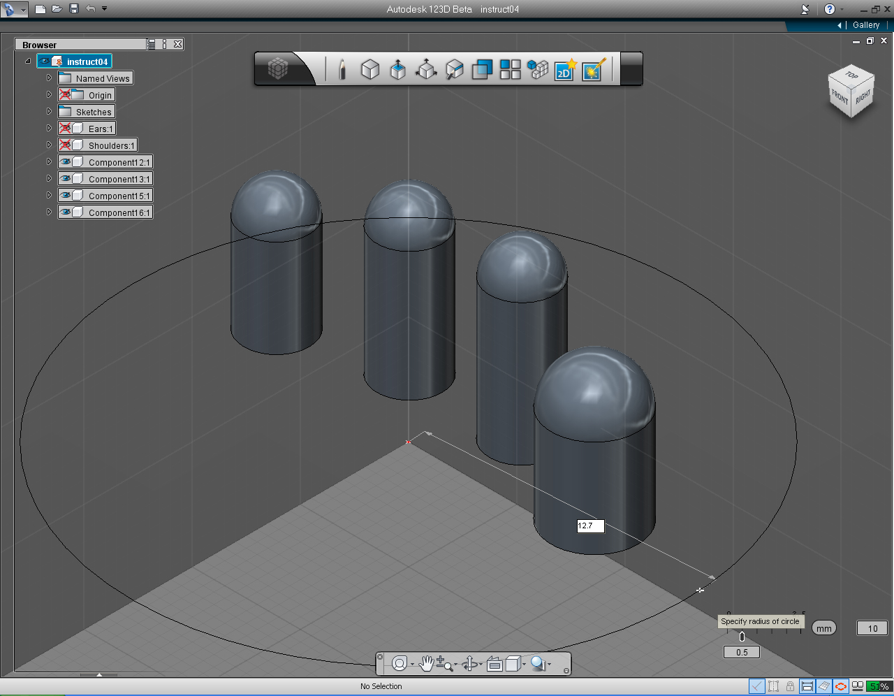
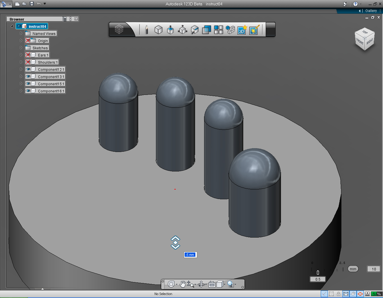
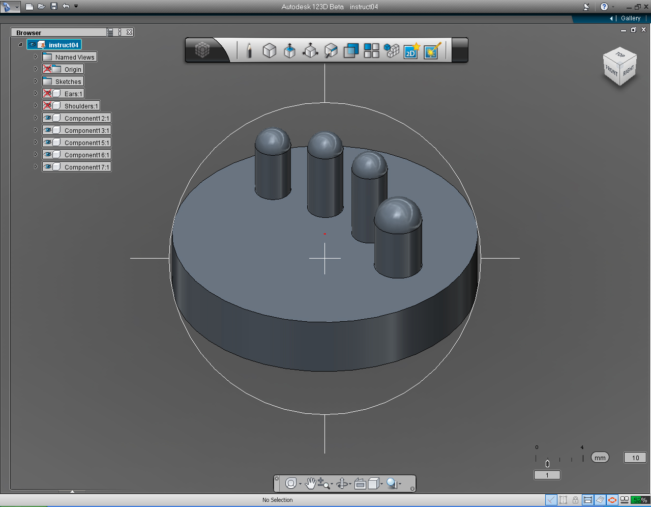
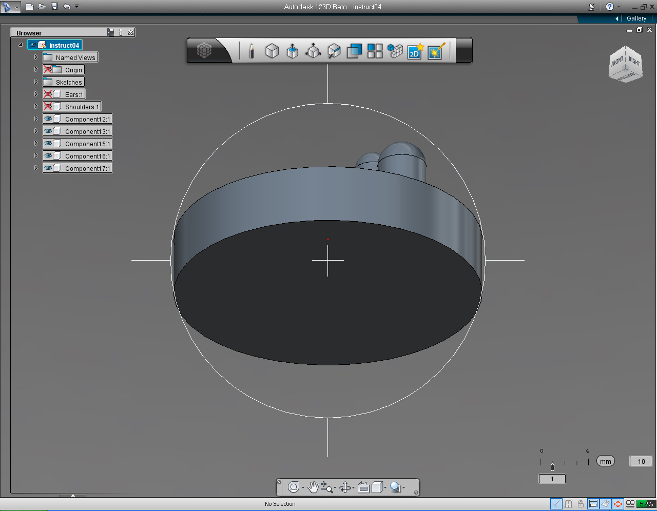
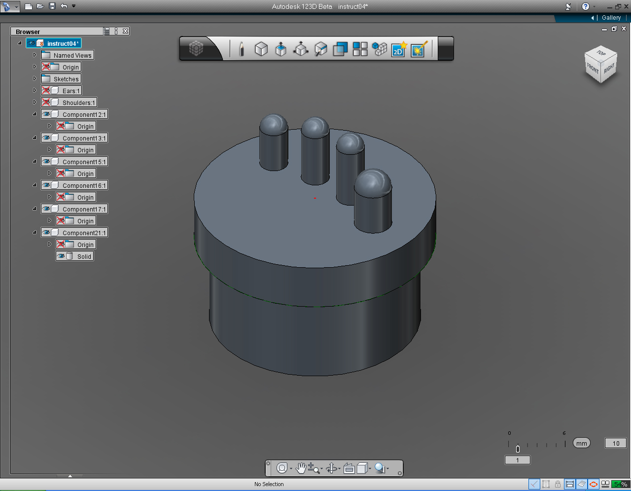
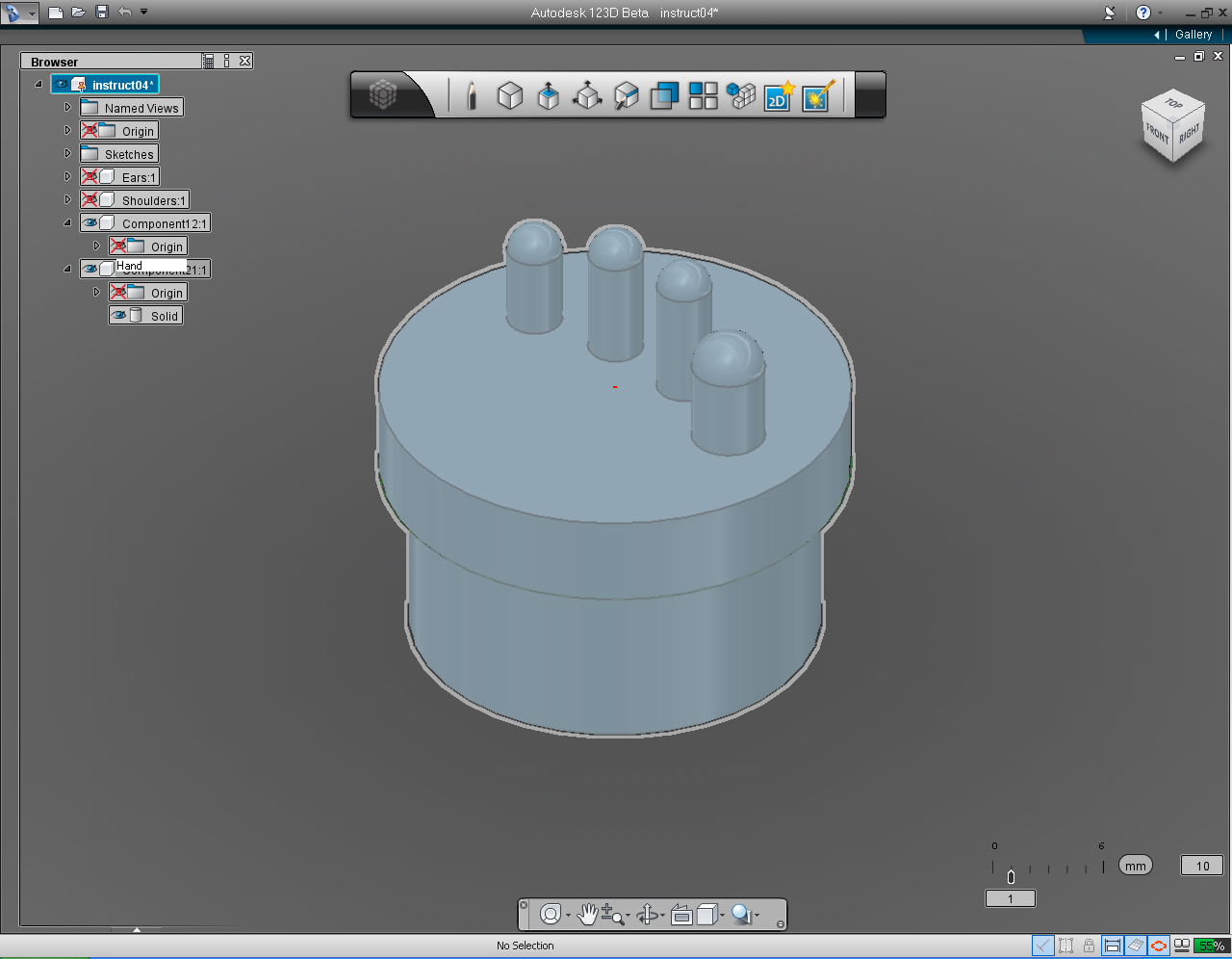
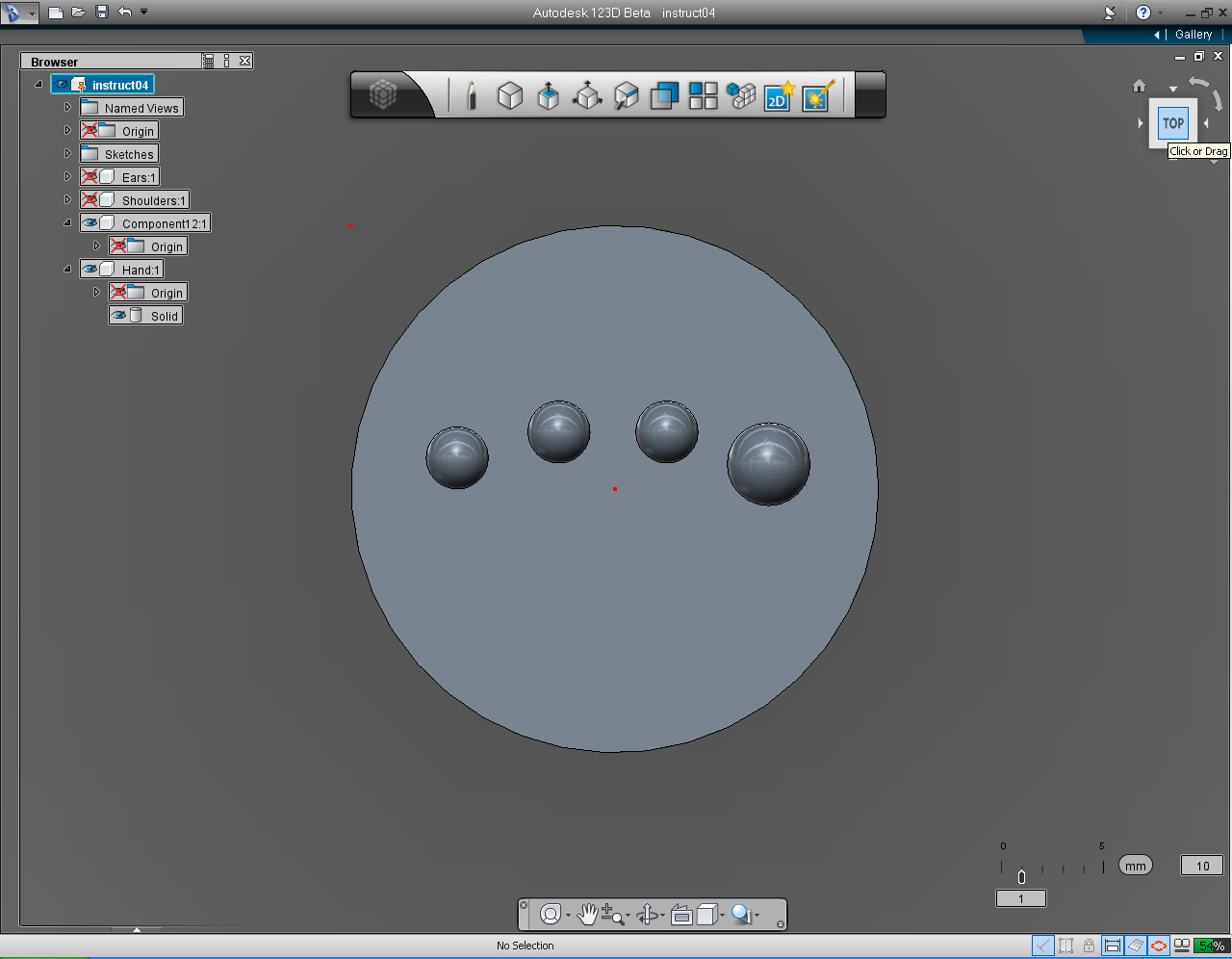
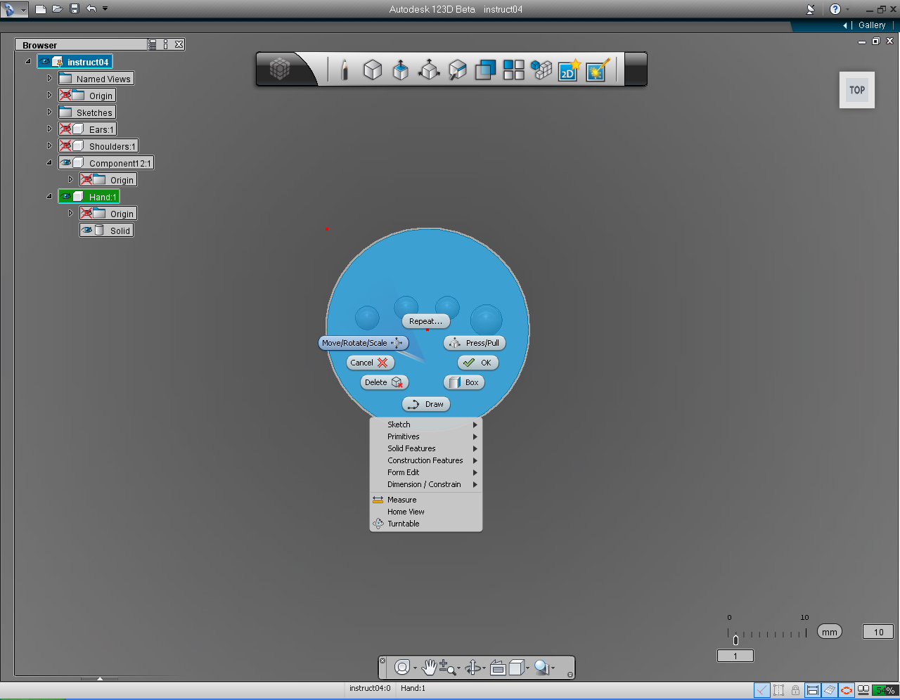
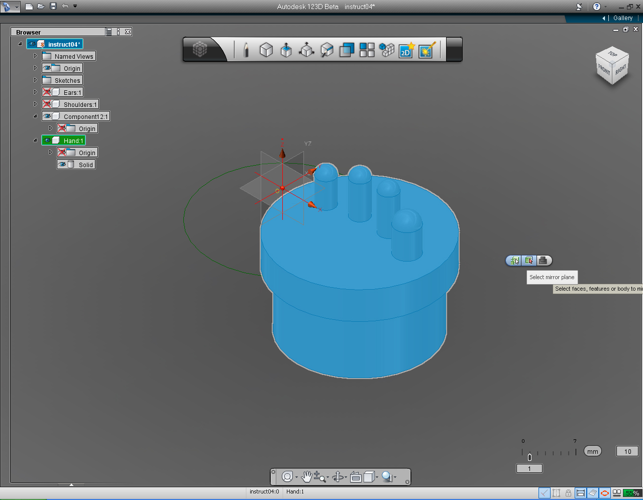
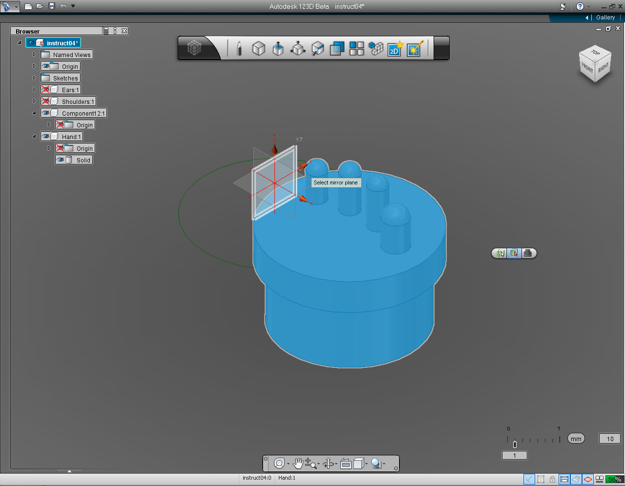
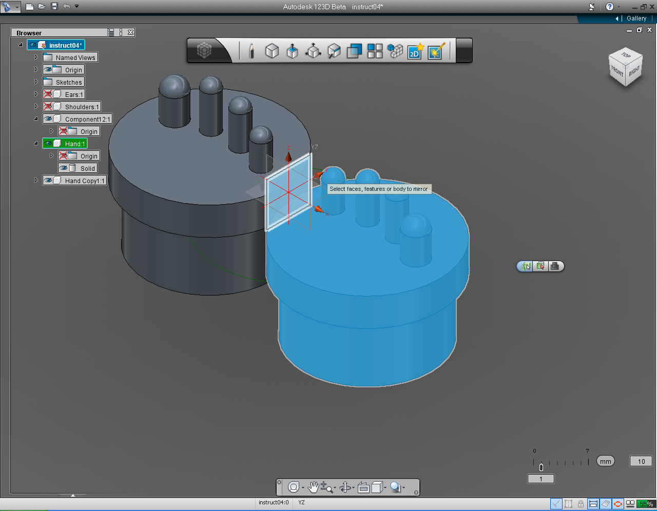
- "Cylinder" function in "Primative" Marking Menu
- "Orbit" function from the "Navigation" Menu
- "Shell" command from the drop-down list of the "Create" Marking Menu
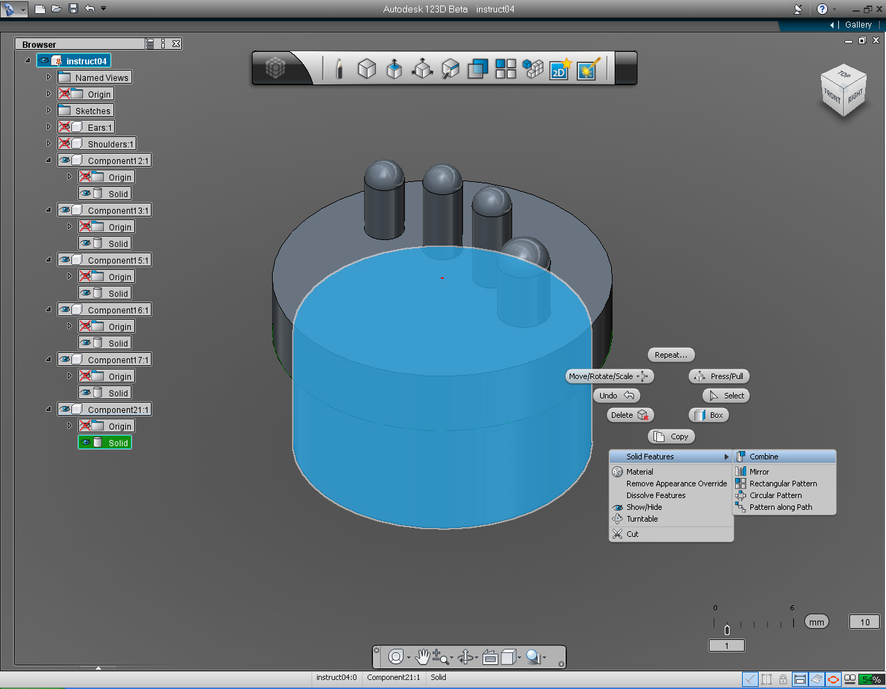
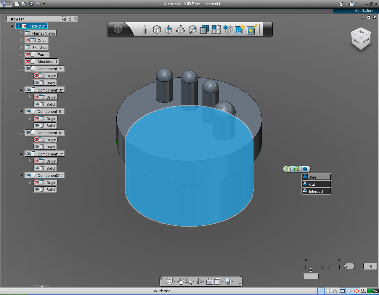
- "Solid Features" -> "Combine" -> "Join"
- "Mirror" pill from the "Pattern" Marking Menu
Continue on from the previous Step (9).
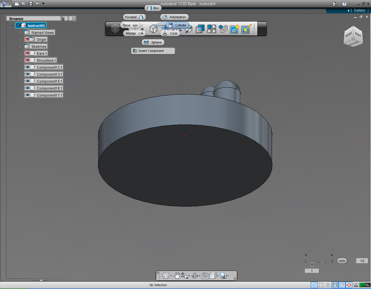
1. Select "Cylinder" pill from the "Create" Marking Menu.
2. Specify the center of the cylinder at 0, 0 or the Origin Coordinate.
3. Specify the radius of the cylinder to 12.7
4. Specify the height of the cylinder (Palm) to -5mm
5. Use the "Orbit" function from the "Navigation" Menu tool rotating around the Palm and Fingers.
6. Set the view to see the bottom of the Palm
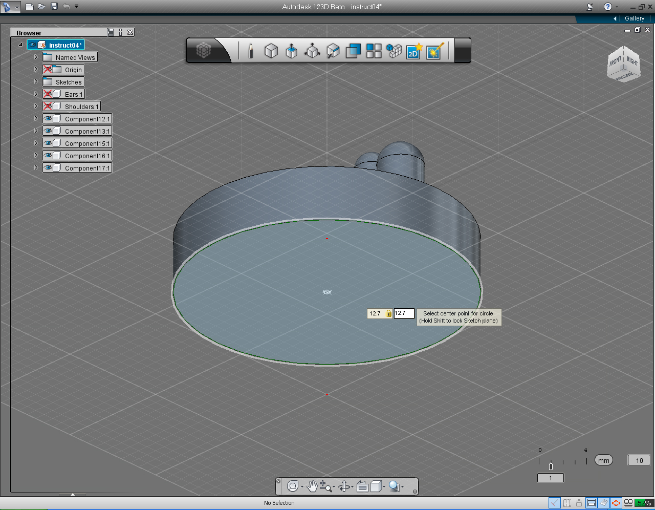
7.To create the Wrist of the hand Select "Cylinder" pill from the "Primative" Marking Menu
8. Move cursor into the bottom surface of the Palm, press the "Shift" key. Then specify the center of the cylinder, at 12.7 and 12.7
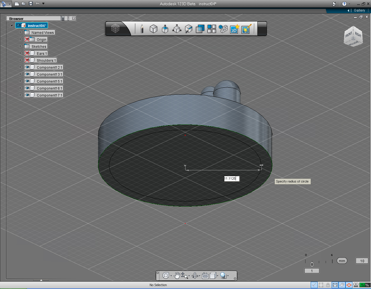
9. Specify the radius of the cylinder as 11.1125
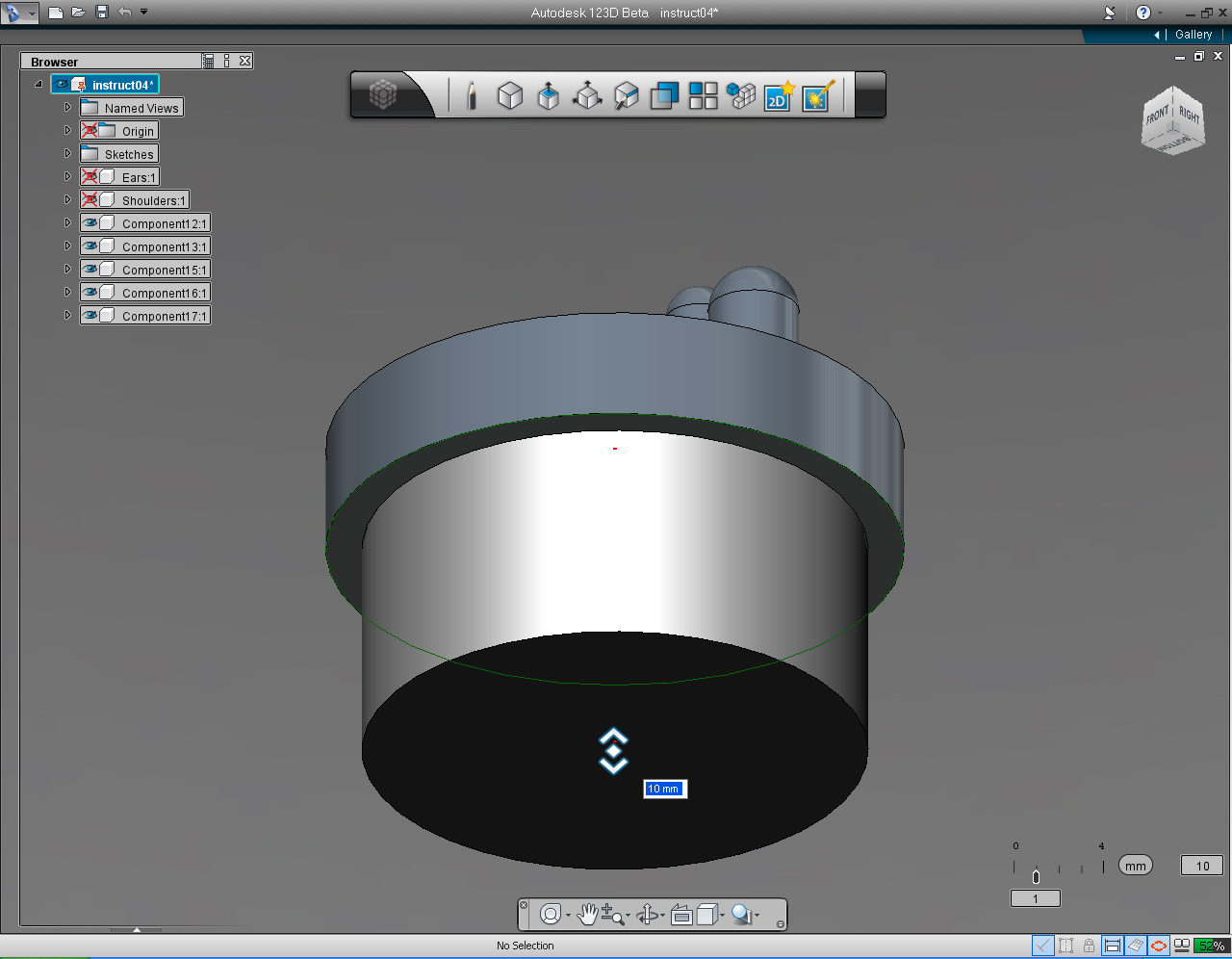
10. Drag the bi-directional arrow to specify the height of the cylinder to be 10mm
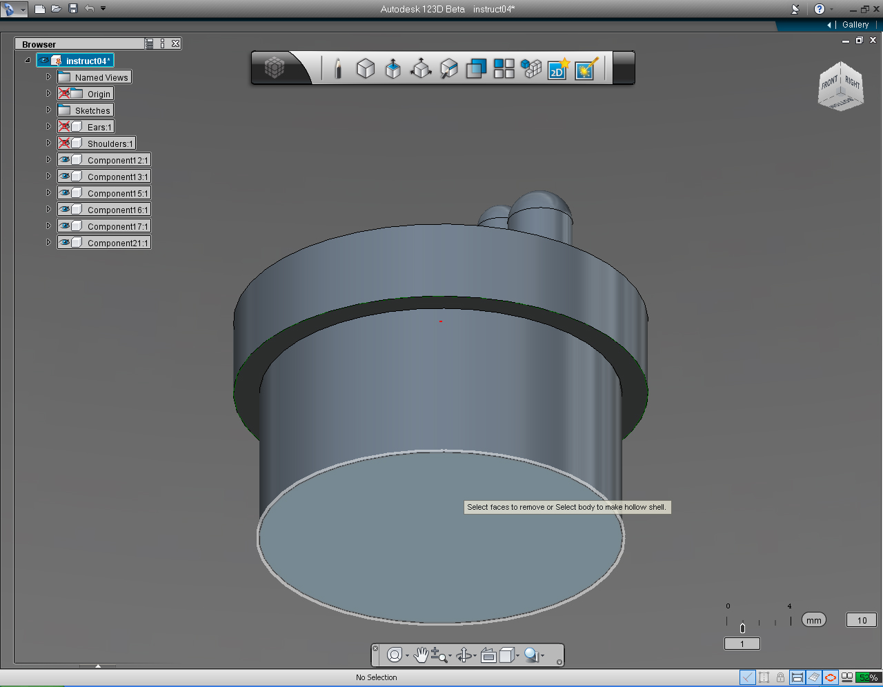
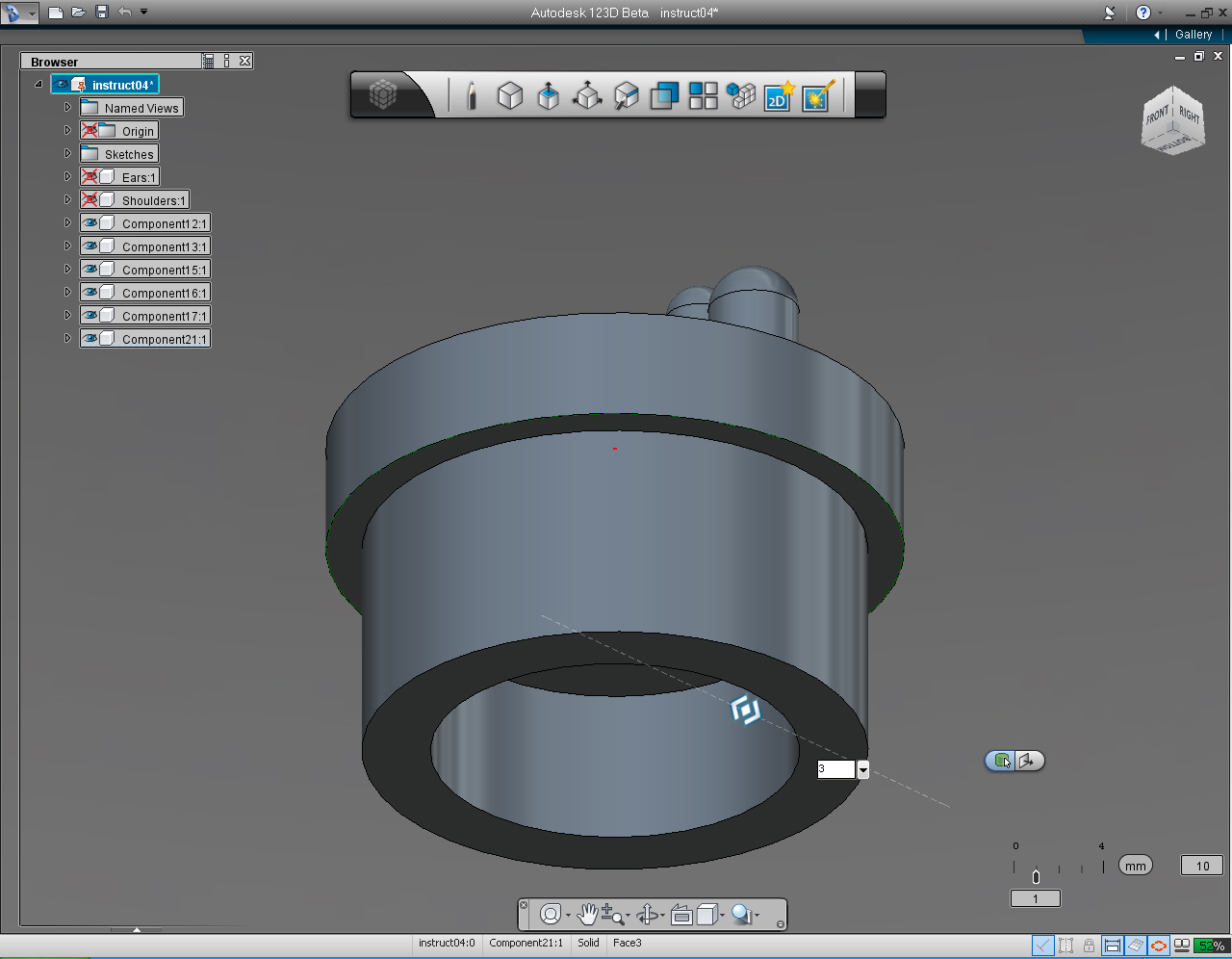
11. Select "Shell" command from the drop-down list of the "Create" Marking Menu
12. Move mouse cursor over the bottom surface of the cylinder.
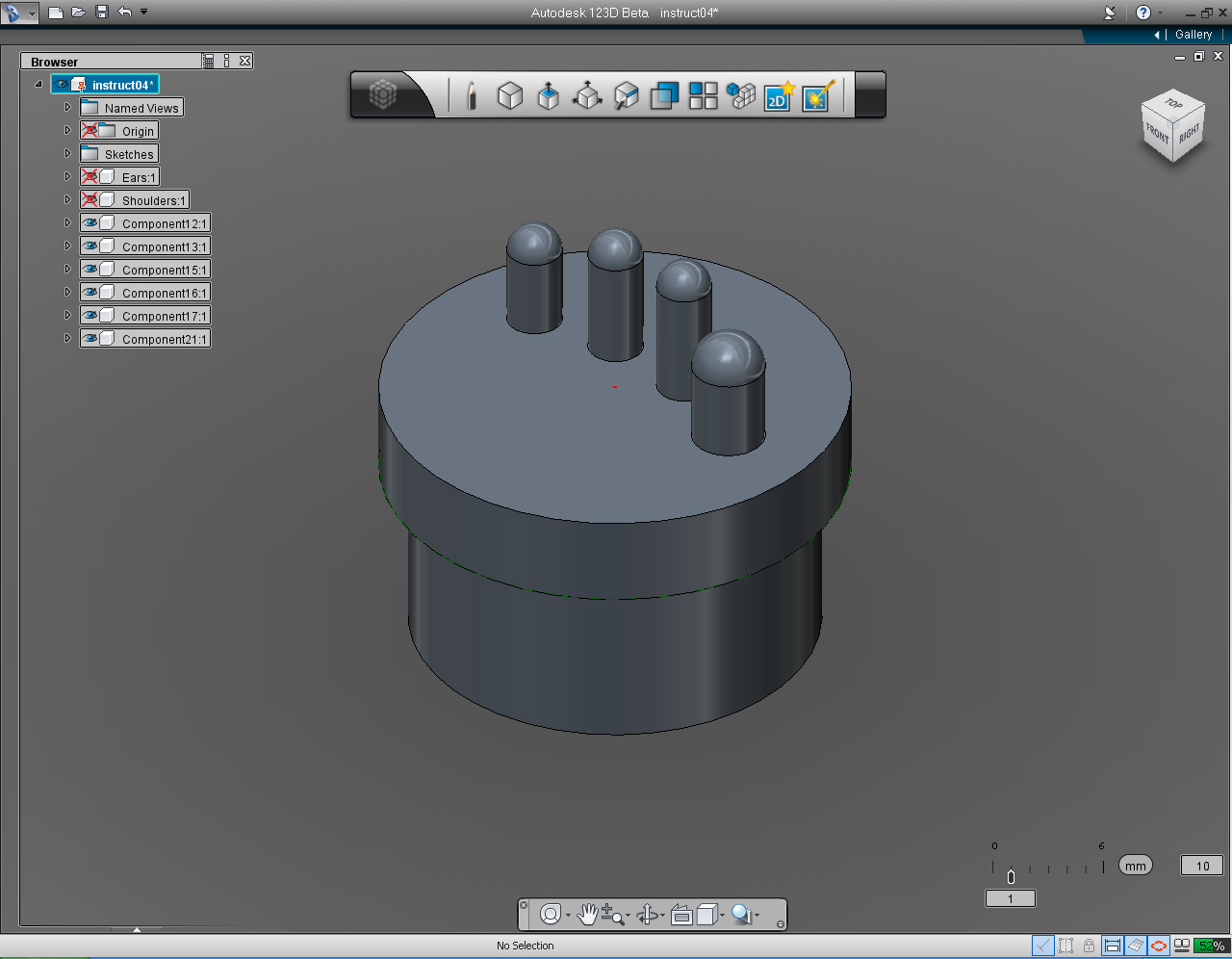
13. Now we have all solid parts of one hand.
14. To combine all the parts together to be one solid hand, first, select the Wrist. And right click to bring up the Marking Menu. Then select "Solid Features" and "Combine"
15. Select the middle icon on the appeared pill menu. Then select "Join" from the list.
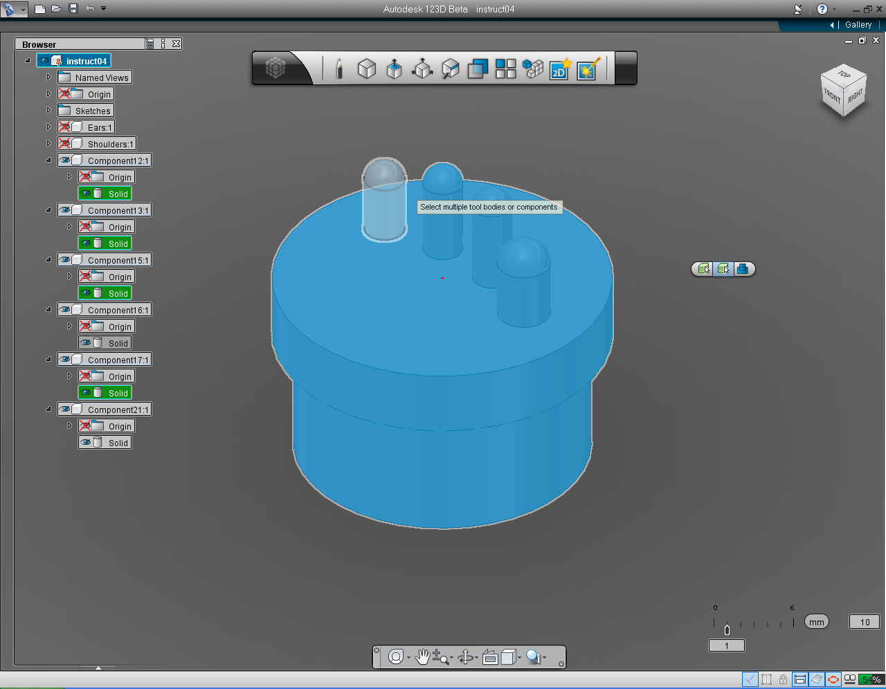
16. Select the Palm, all the fngers.
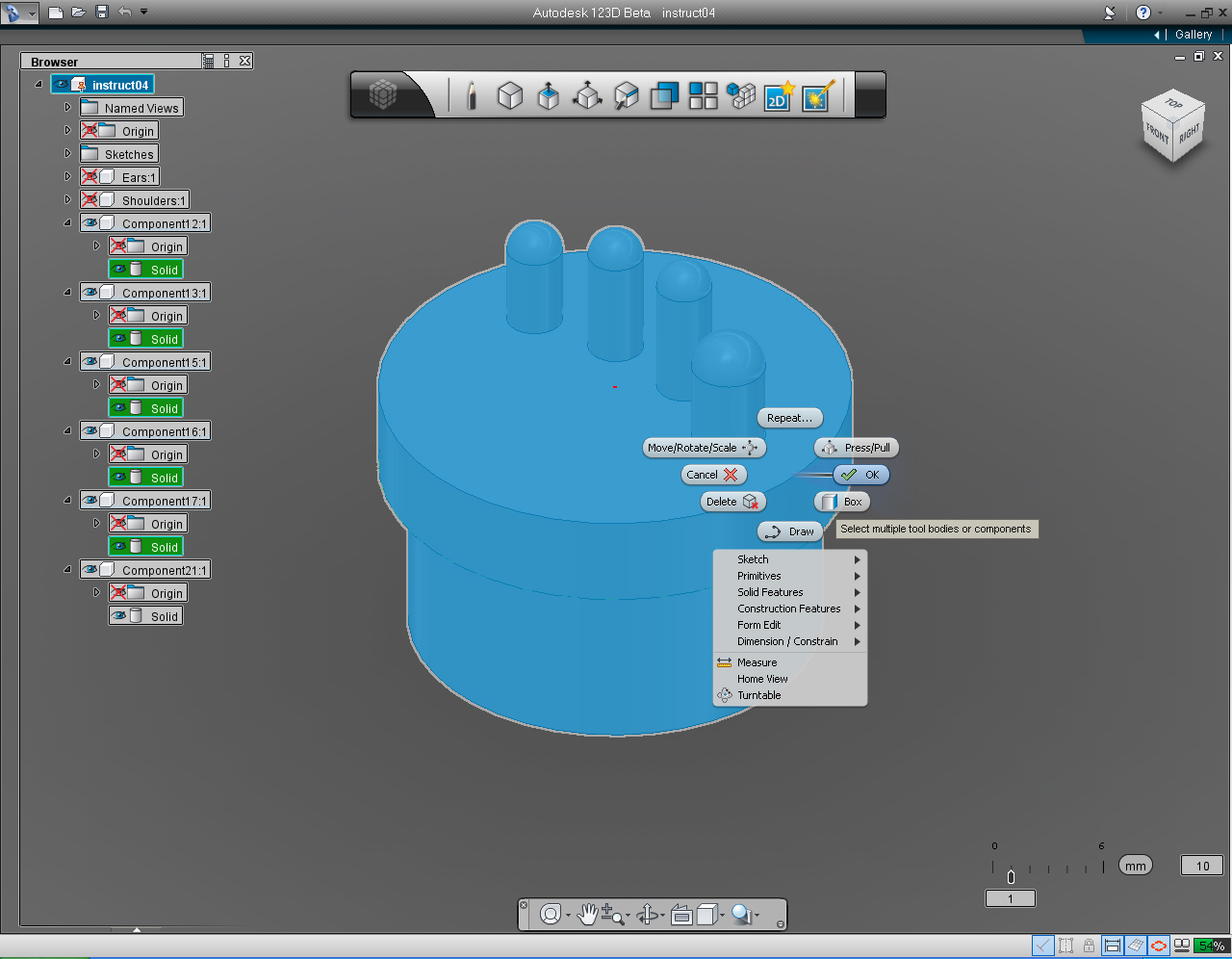
17. Right click the mouse to bring up the Marking Menu. Then select "OK" pill.
18. Now we have all the separate parts of hand combined to one.
19. Rename the component that only have "Solid" model in it (the last one on the list) to "Hand". Then delete all the "Component" that does not have "Solid" anymore.
20. Select the TOP view on the "View Cube".
21. "Scroll" the mouse scroll wheel (middle button) to adjust the size of the hand to look smaller.
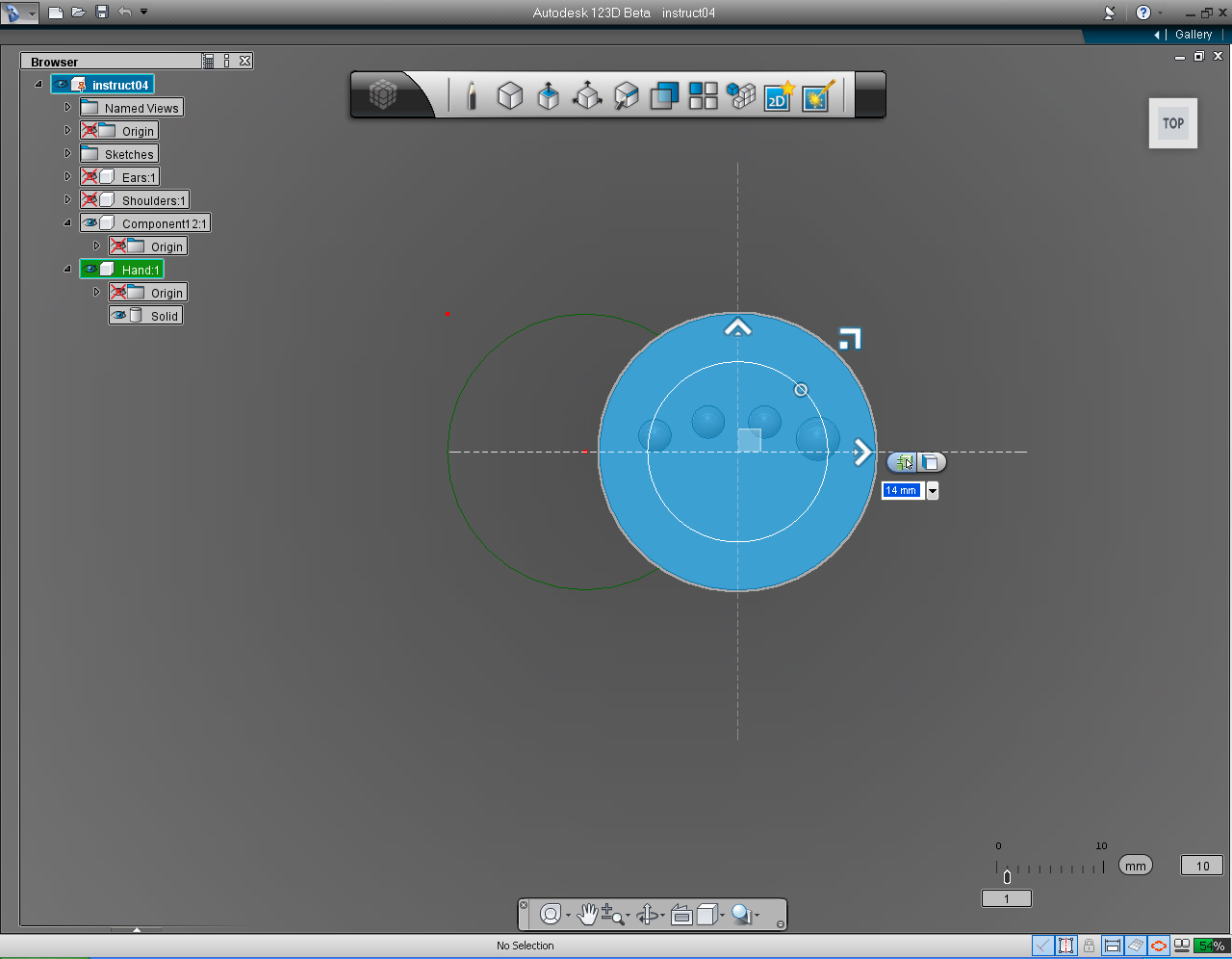
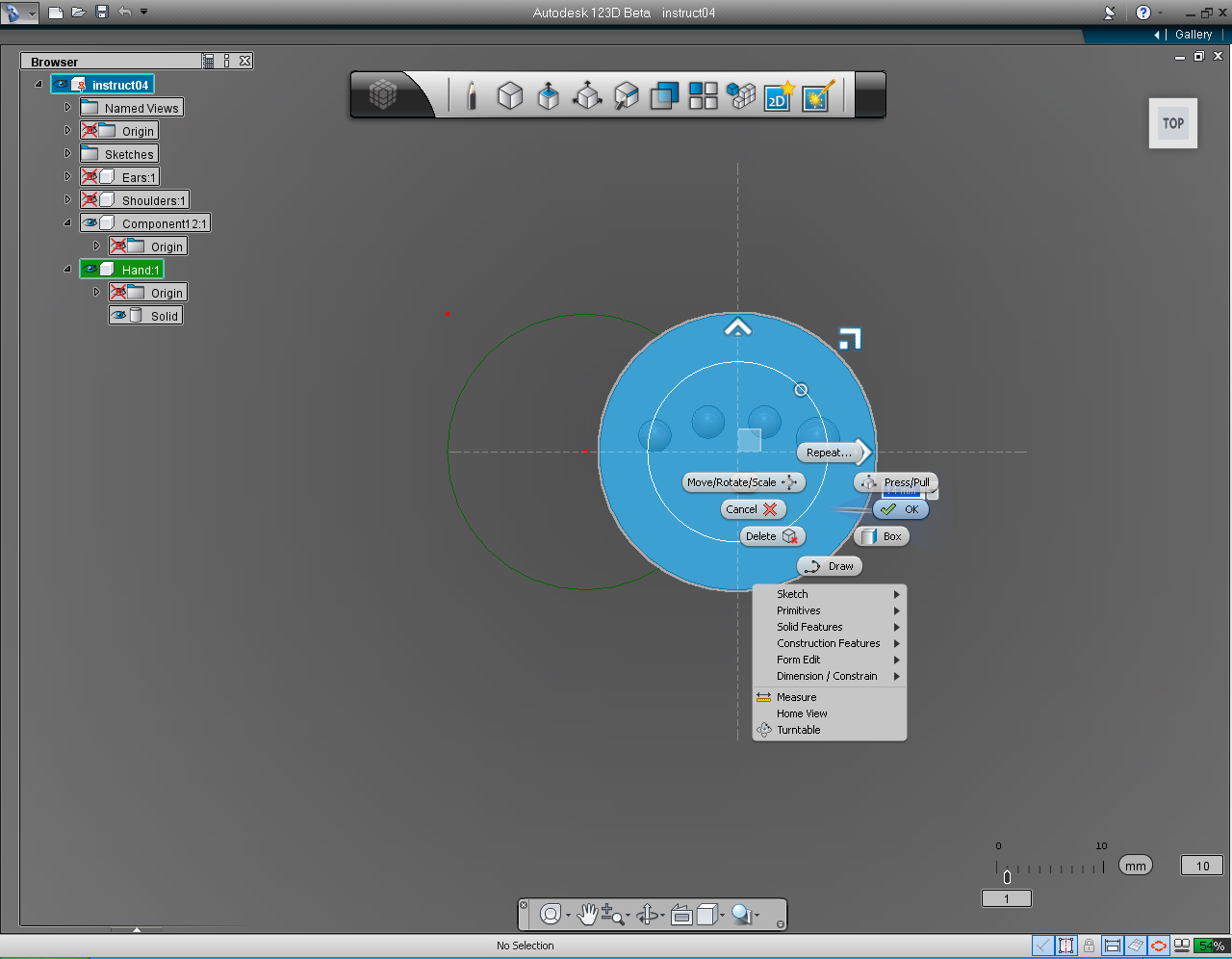
22. Right click the mouse button to bring up the Marking Menu. Select the "Move/Rotate/Scale" pill.
23. Drag the horizontal arrow to move the hand to 14mm to the right.
24. Right click the mouse to bring up the Marking Menu again. And select "OK" pill to commit.
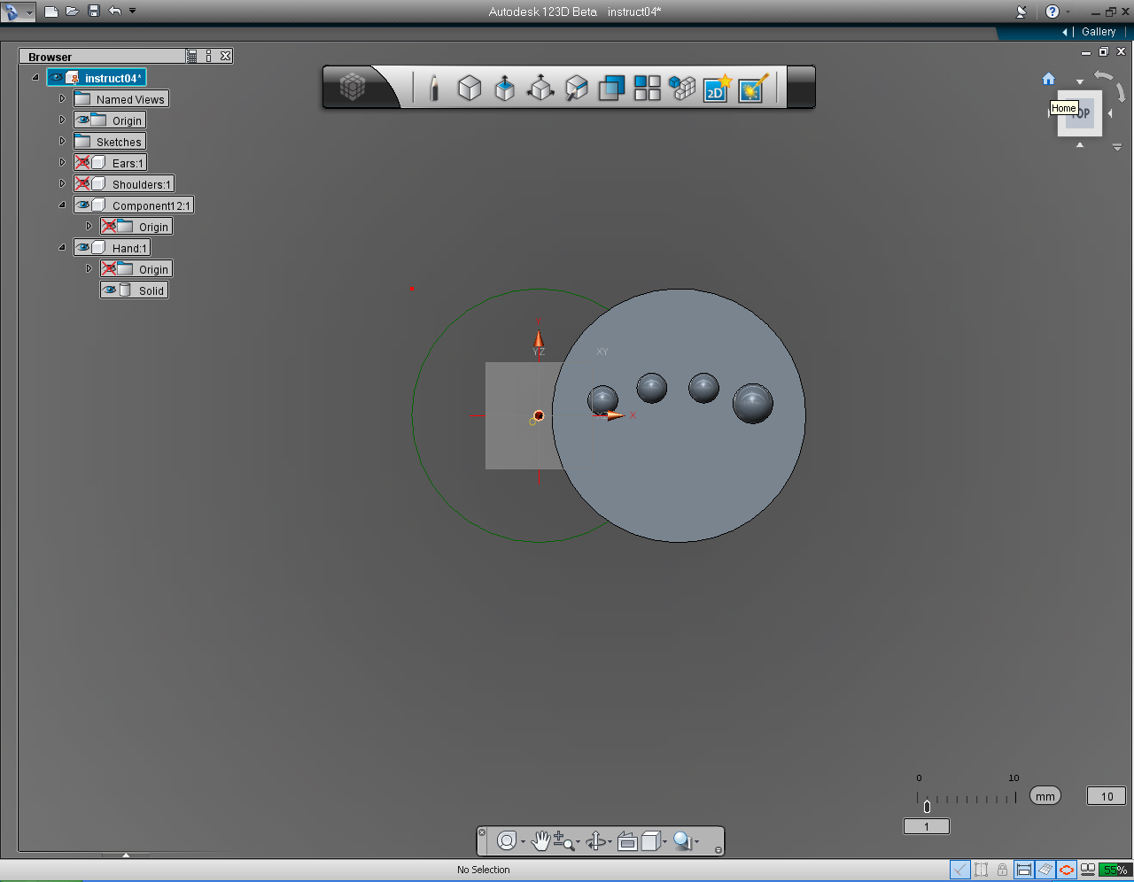
25. Unhide the Origin Coordinate.
26. Set the "View Cube" to Home position.
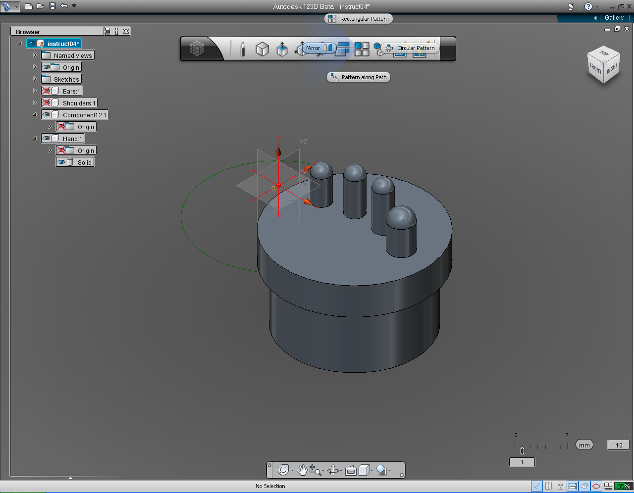
27. Select "Mirror" pill from the "Pattern" Marking Menu
28. From the appeared pill menu, select the middle icon.
29. Select the YZ plane to "Mirror" the hand.
30. Right click the mouse to bring up the Marking Menu again. Then Select the "OK" pill to commit the command.
Hands: Part 3 - Left and Right Hands
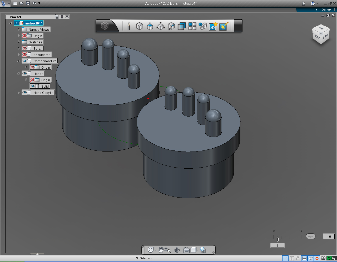
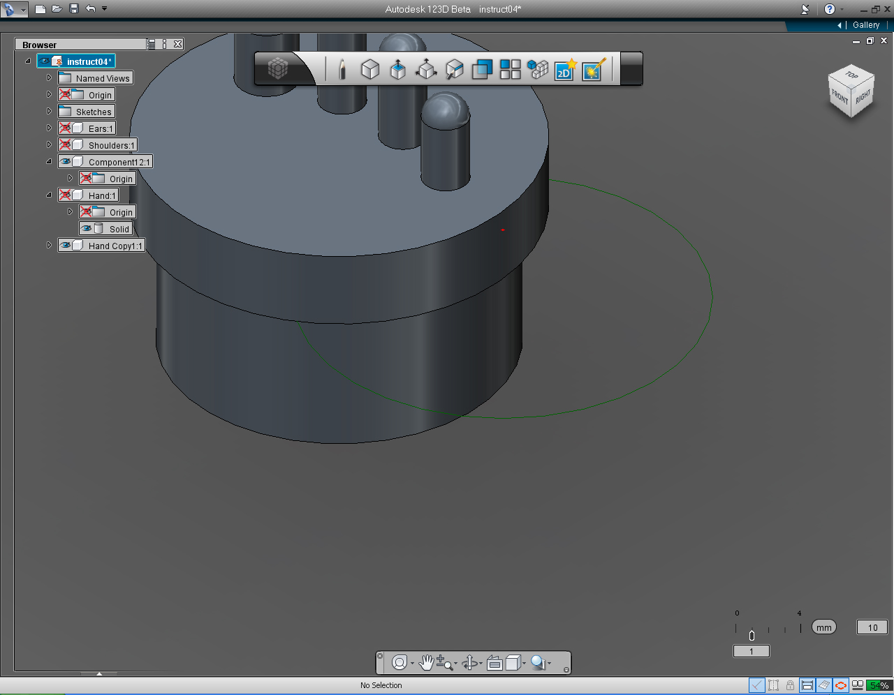
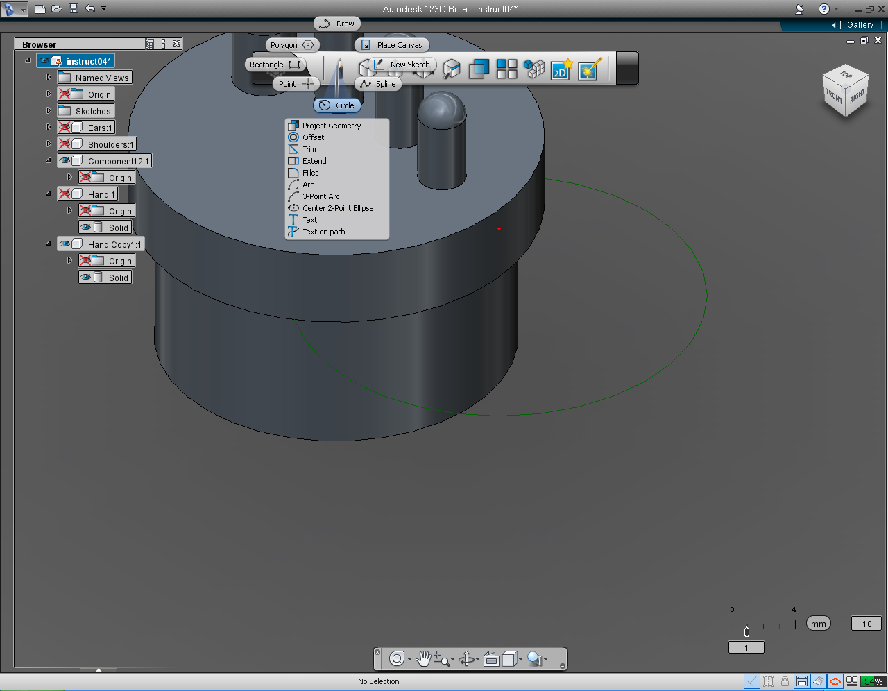
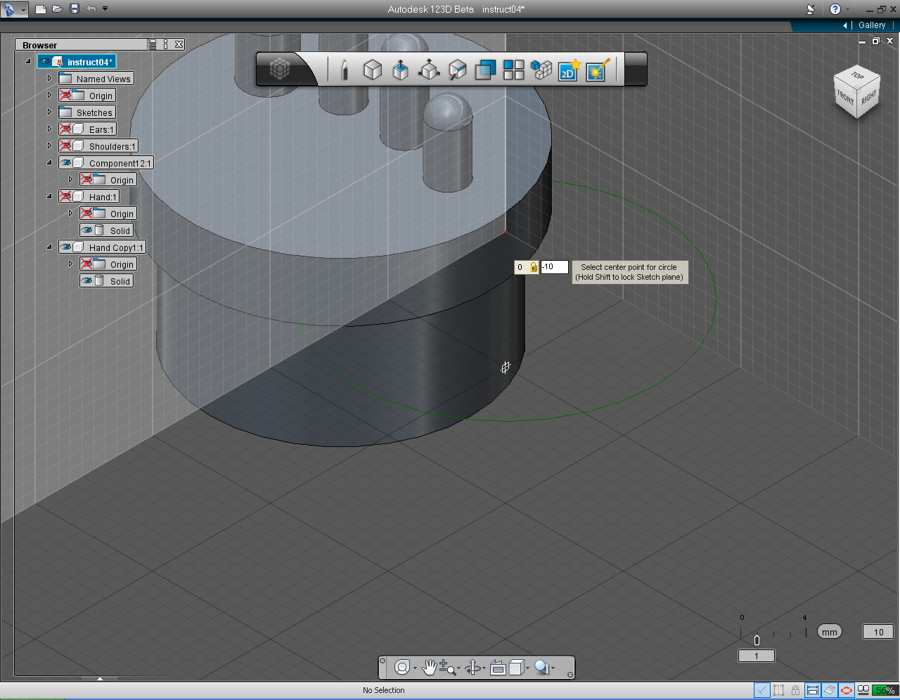
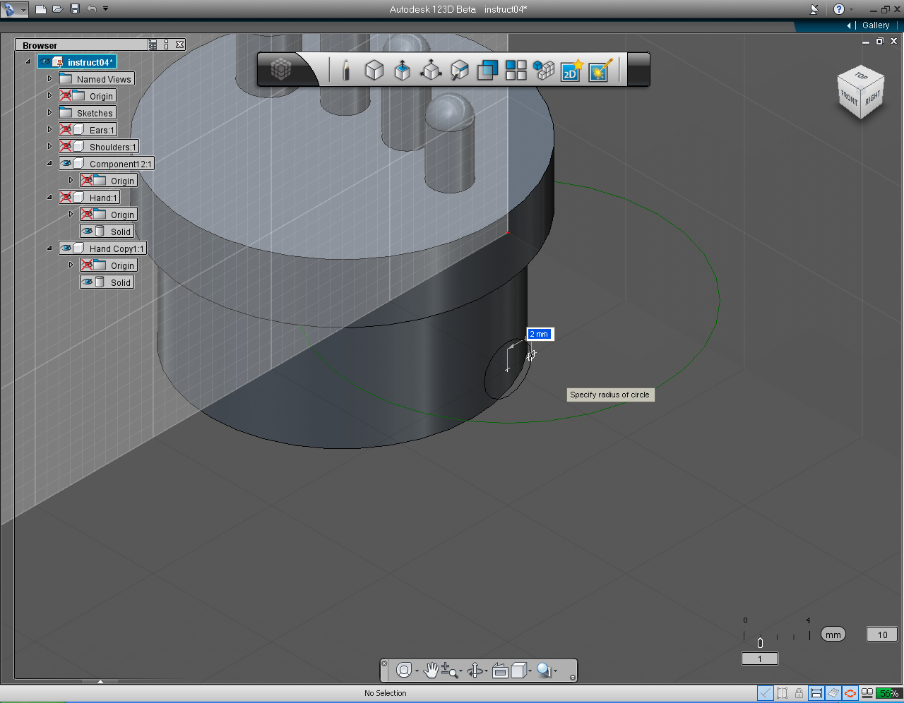
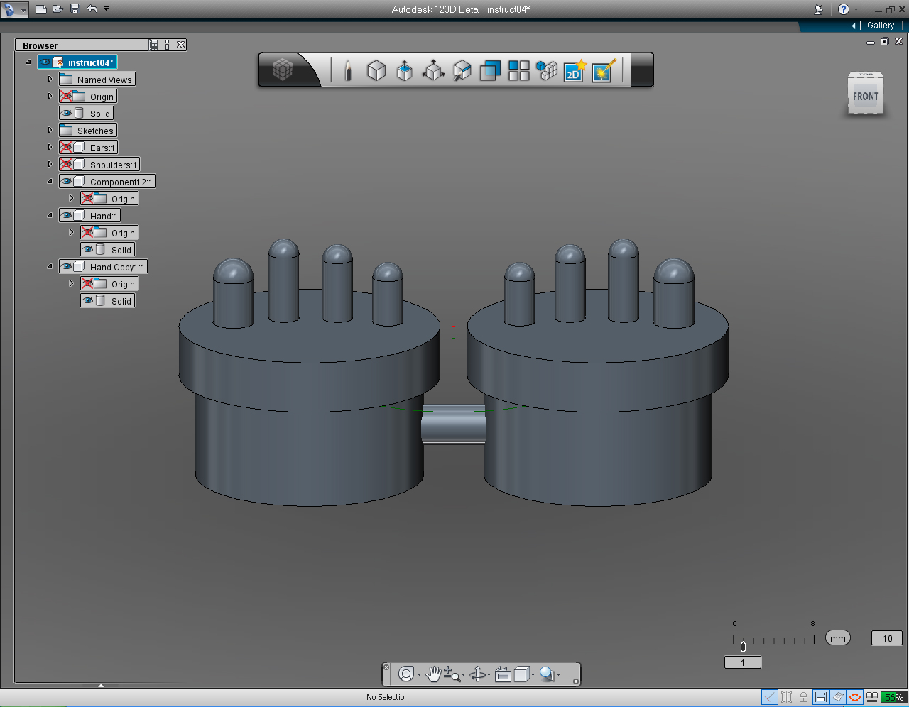
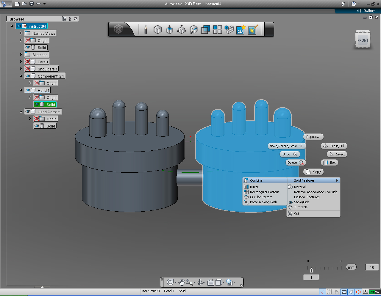
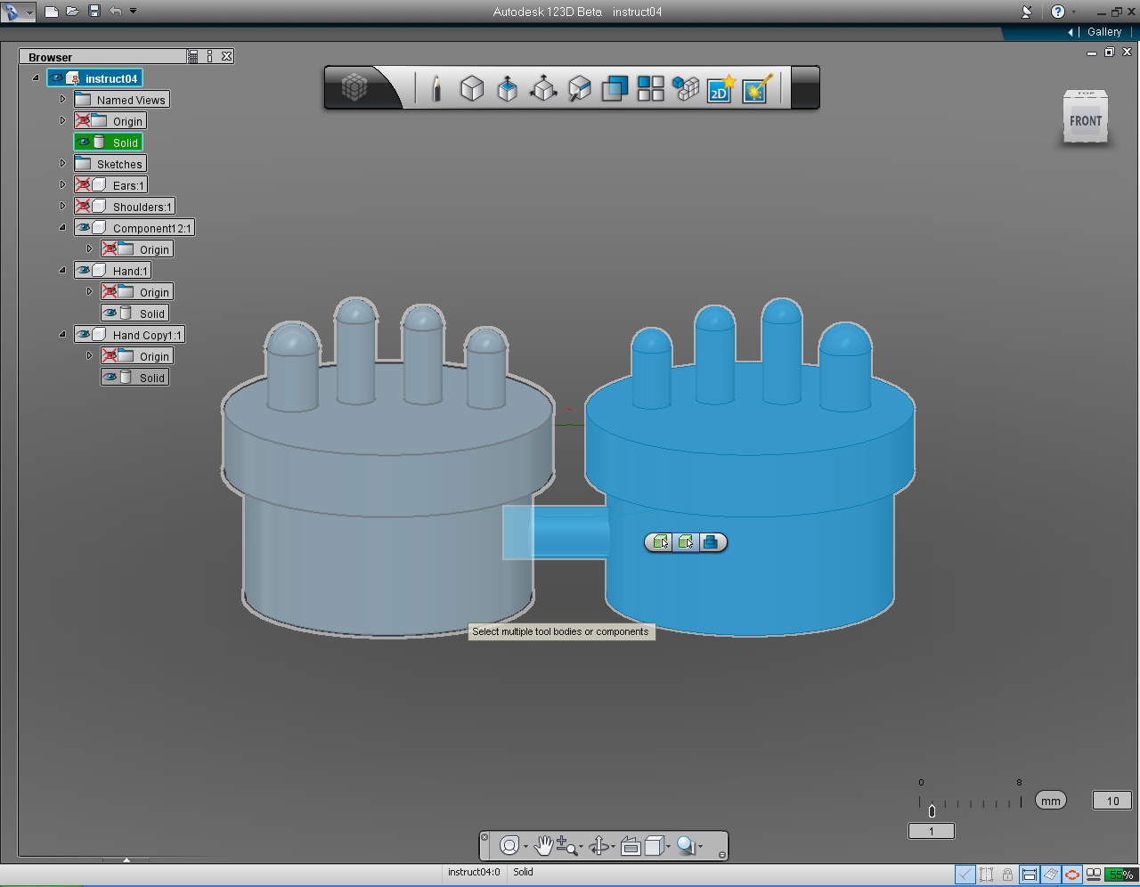
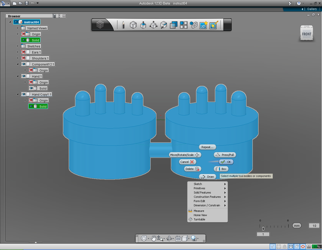
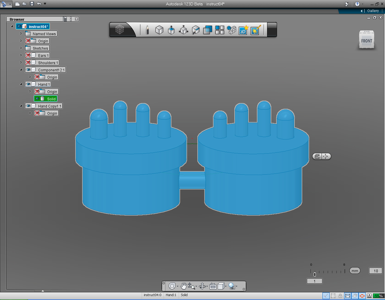
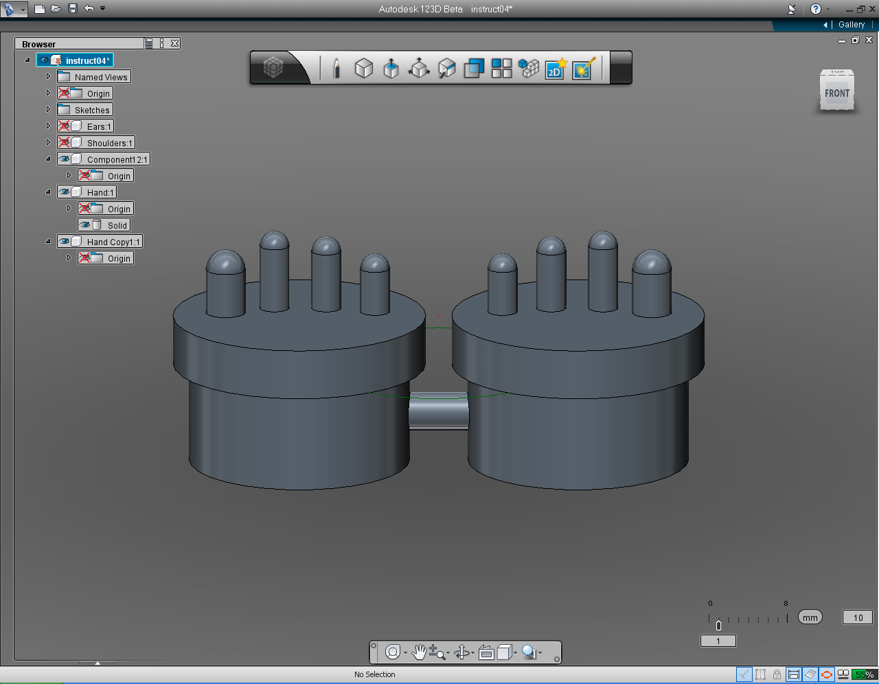
- "New Component" function in the "Feature Browser" Menu
- "Copy" function in the "Feature Browser" Menu
- "Paste" function in the "Feature Browser" Menu
- "Circle" pill in "Sketch" tool in Main Tool Bar.
- "Extrude" pill in "Create" tool in Main Tool Bar.
- "Symmetric" in "FreeForm" tool in Main Tool bar or in "Extrude" submenu
- "Combine" pill in "Create" tool in Main Tool Bar
Continue on from the last Step (10).
1. Copy the solid left hand model to "New Component", function in the "Feature Browser" ( I moved my right hand to "Hand Copy 1",
If you not sure how to do it, just go back to Step 6.)
Why we have to do this? One reason is that we want to hide right hand so it will not obstruct the view, while we are working on the joining cylinder.
2. Hide the right hand in Feature Browser.
3. Start to draw the "Circle" on the "Right Plane", using the "Circle" pill from the "Sketch" Marking Menu.
4. Set the center of the circle to 0 and -10.
5. Assign the radius of the circle as 2mm
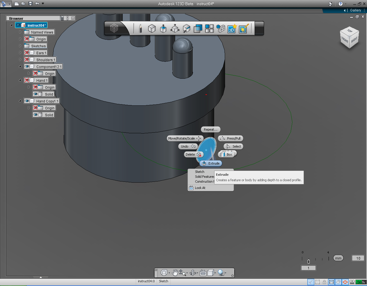
6. Select the circle that we just drawn. Right click at the circle to brign up Marking Menu, then select "Extrude" pill from the menu.
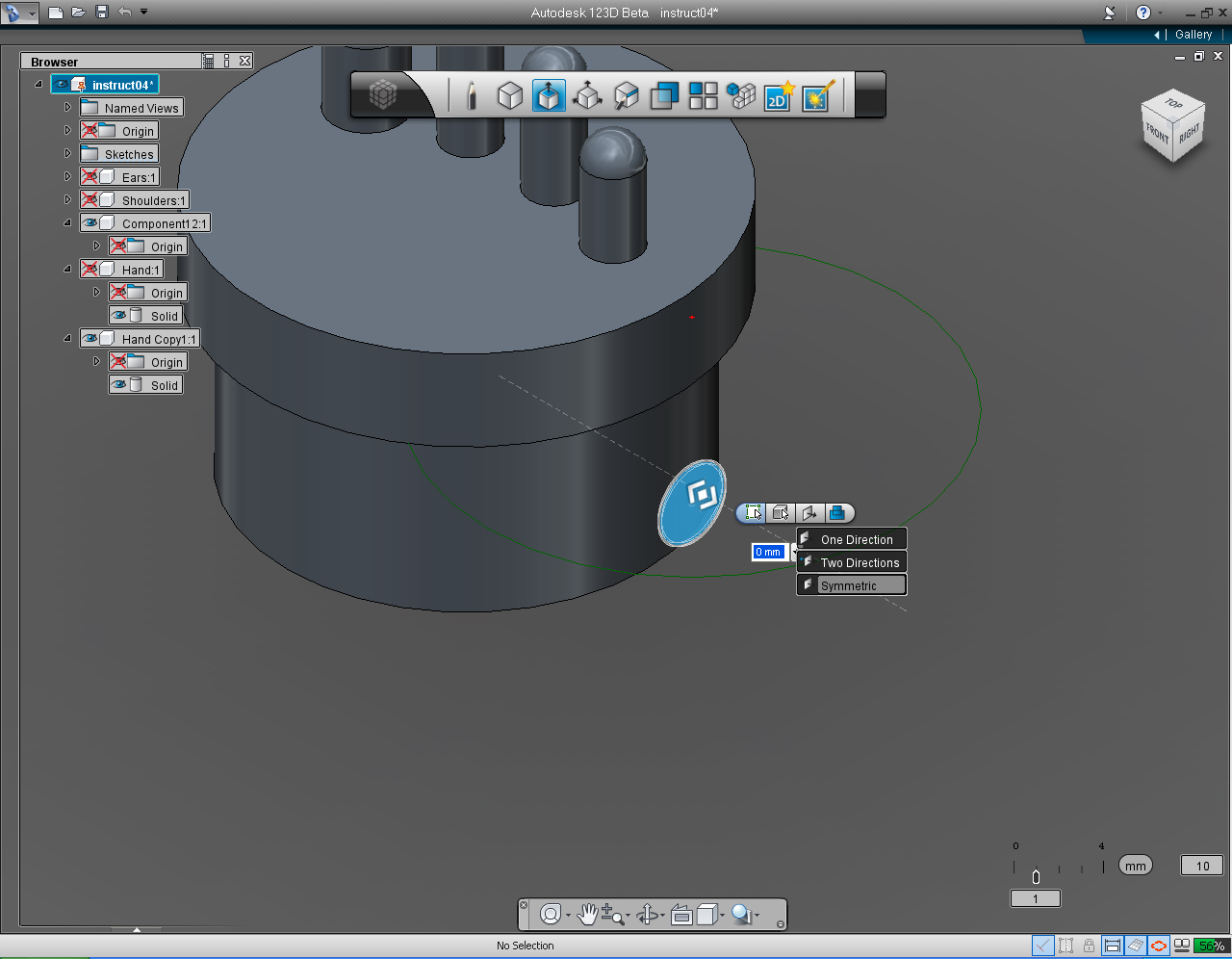
7. On the "Extrude" submenu, select the fourth or right most icon on the pill. Then select "Symmetric". This will extrude the circle in both direction.
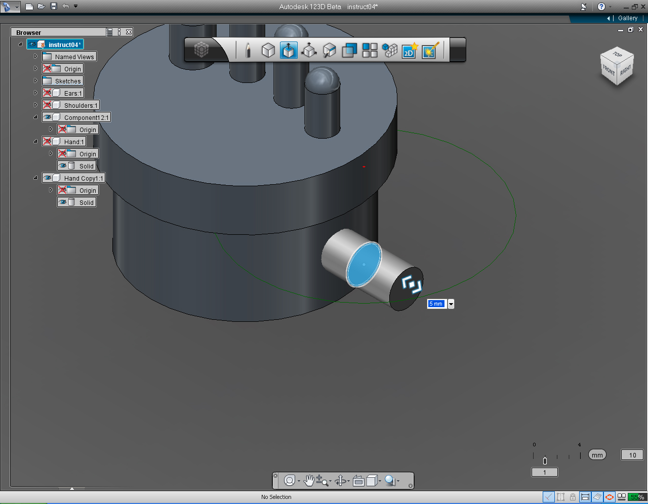
8. Drag the bidirectional arrow (or use keyboard input) to 4.5 unit.
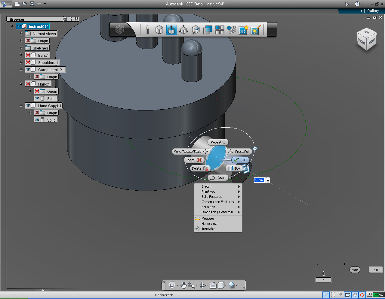
9. Right click to bring the Marking Menu, then select "OK" pill to commit the command.
10. Unhide the Hand 1 (right hand)
11. Right click on the right hand solid model to bring up Marking Menu. Then select "Combine" from the list.
12. Select the cylinder and left hand, to combine to right hand solid model.
13. Right click mouse to bring up Marking Menu, Then Click "OK" to commit command.
14. Now we got both hands and an extruded solid circle "joined" together.
15. Delete all the unnecessary components that did not contain Solid model anymore (i.e Component 2:1 and Hand Copy1:1).
After you're done with the shoulders, save the file.
Eyes: Part 1 - Eye Lens


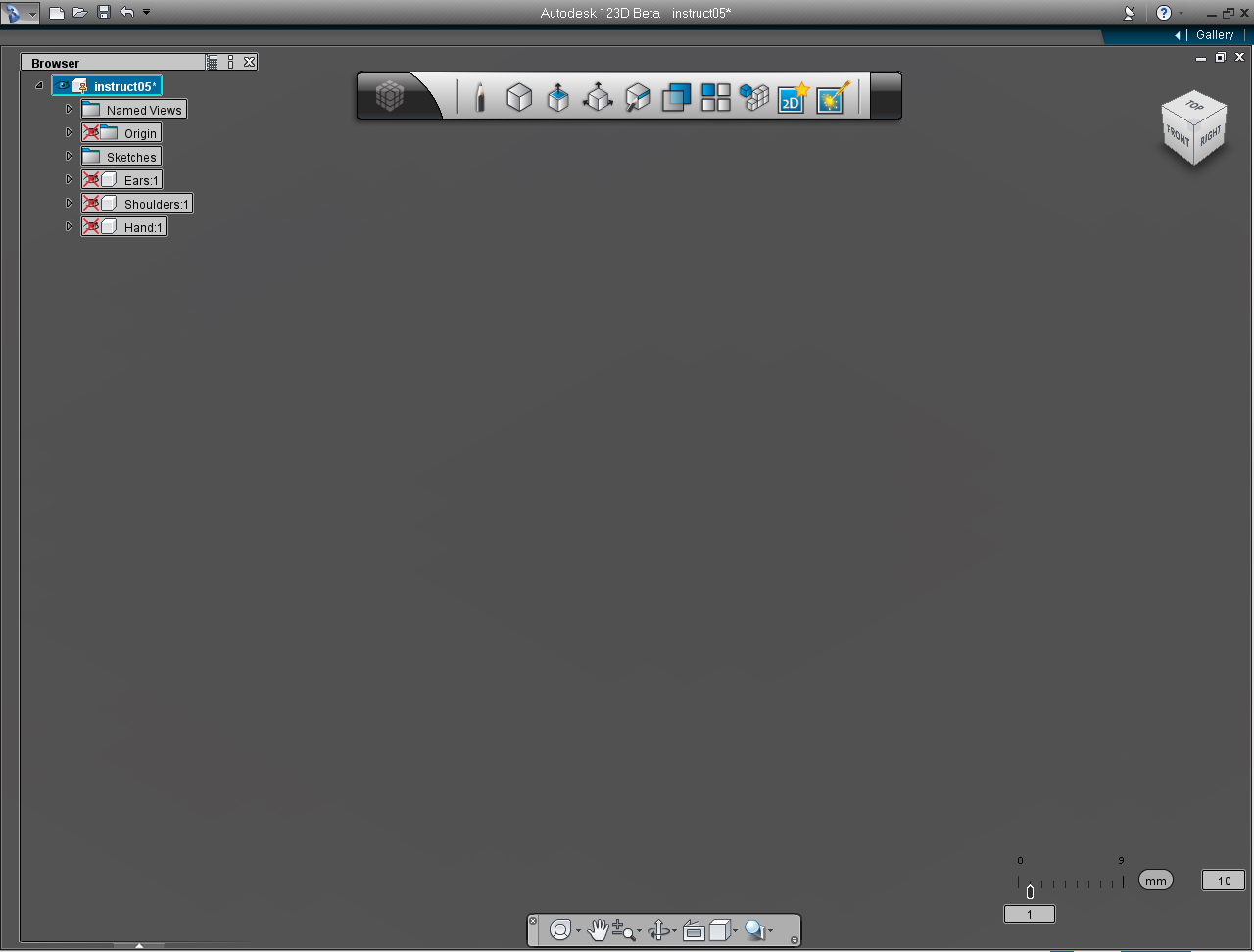
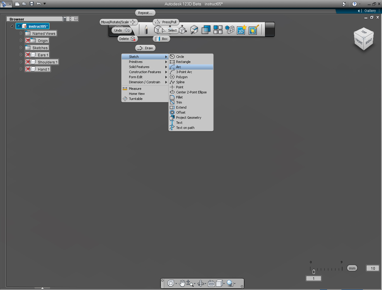
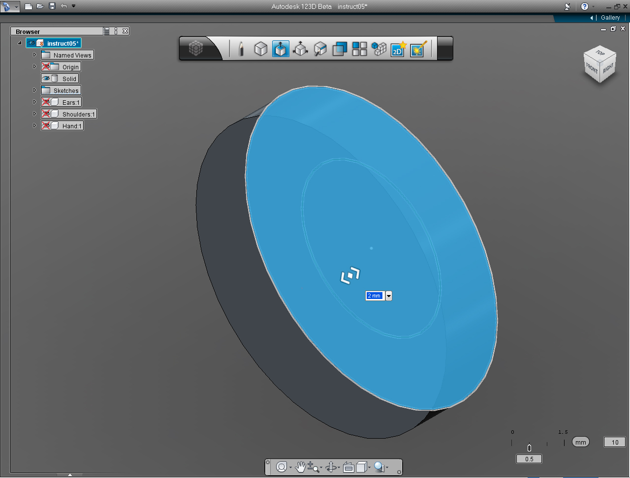
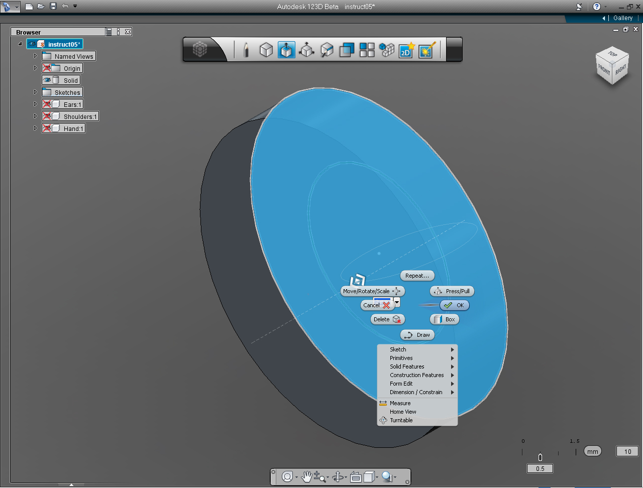
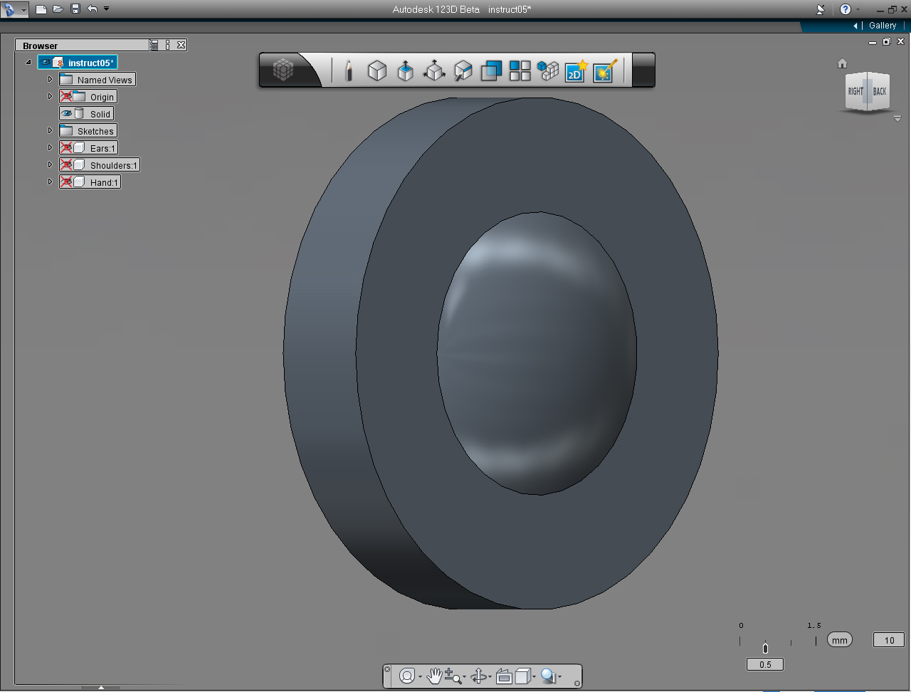
We are now at the half way point to be done with the project.
Now, we are about to create last 3D model for the project, Eyes and Eyebrows. As usuall we have the rendering image of the finish model, and dimensions on the cross-section sketch.
Up to this point, you have an idea how you want to go with creating this 3D model.
As I mentioned earlier, There are many possibilities, and choices of commands that you could come up to finish this simple model,
for example,
Draw all the lines with "Draw" function in the "Sketch" bucket, then "Revolve" it, just like what we did with the ear model. Or we could use the same methods that we use in the previous step (Step 7), when we create hands model, using "Cylinder" function in the "Create" Marking Menu or bucket, or you could use different commands to create the model, the possibilities are endless!
Some of the commands may be repeated in these step to create eyes and brows. But that will do you good, you earn more experience doing so. Like an old saying said "Practices make perfect!"
Summary of the commands to use in this step:
- "Sketch" -> "Arc"
- "Solid Features" -> "Revolve"
- "Circle" pill in the "Sketch" Marking Menu
And these are the steps:
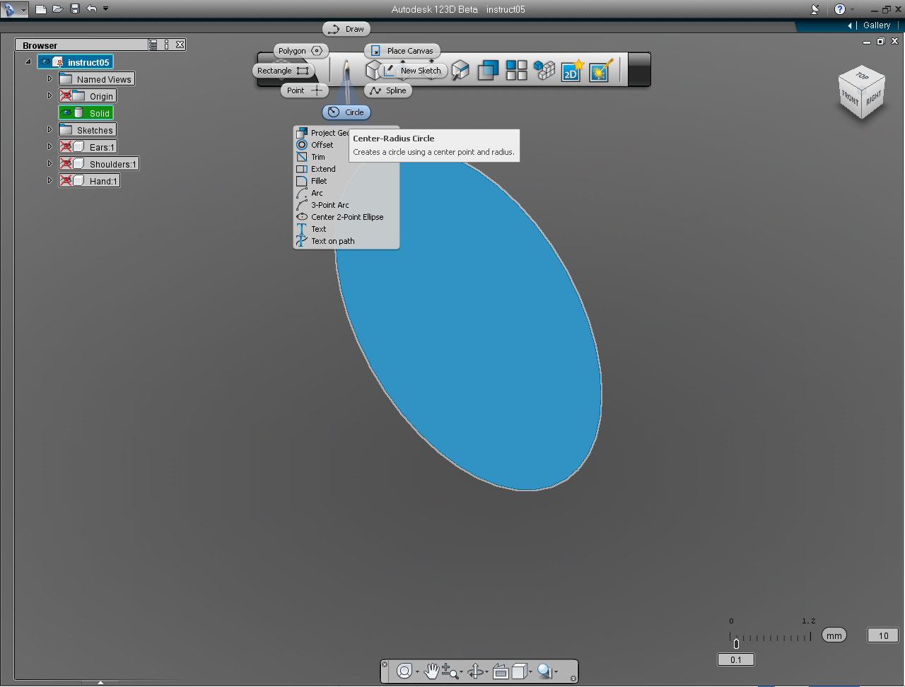
1. Rendering of the eyes with eyebrows 3D model that we are creating.
2. Cross-section of the eye, with dimension to be drawn in 123D. Eyebrows will be added after we created the eyes.
3. Hide all the Solid model of the previously created Steps(Ears, Shoulders, and Hands.)
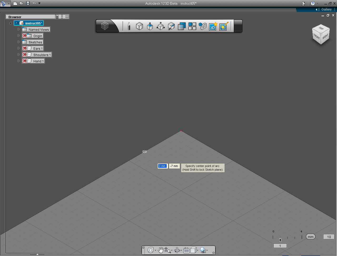
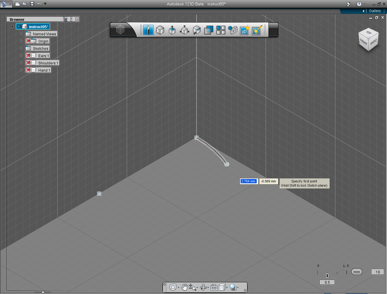
4. On the "Sketch" Marking Menu, Select "Sketch" -> "Arc" from the list.
5. Specify the center point of Arc at 0, -7 coordinate on the TOP plane.
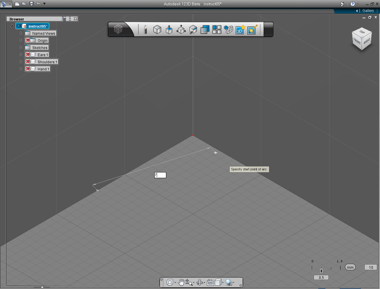
6. Specify the start point of arc at 0, 0.
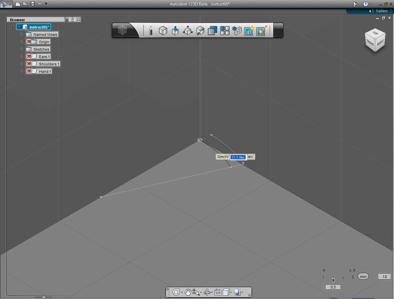
7. Specify the end point of arc by type in the value of 23.3.
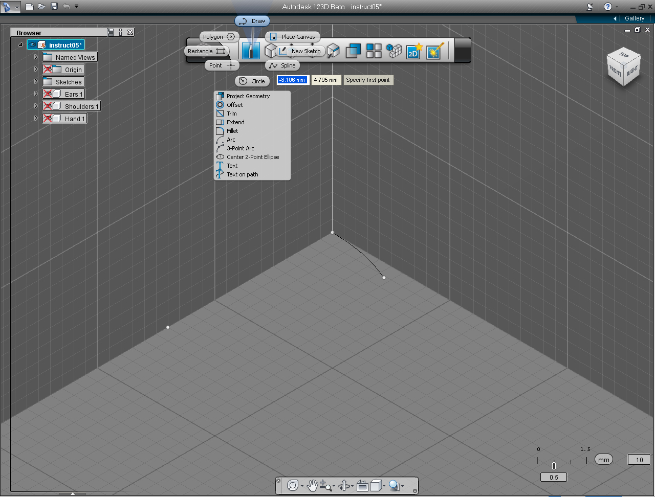
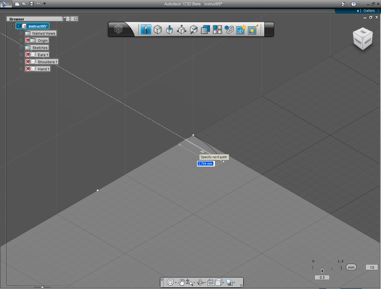
8. Select "Draw" pill in "Sketch" Marking Menu.
9. Click at the end point of arc.
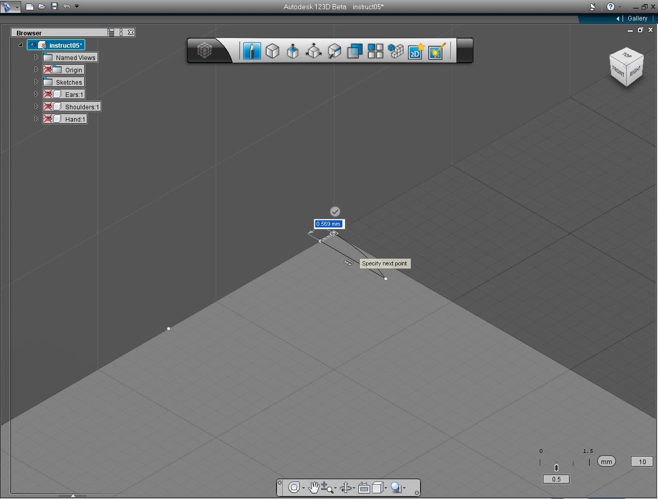
10. Drag the cursor toward left to perpendicular to the X coordinate line, then click to create line.
11. Drag the cursor to specify the end point of line at 0, 0 coordinate or the starting point of the arc.
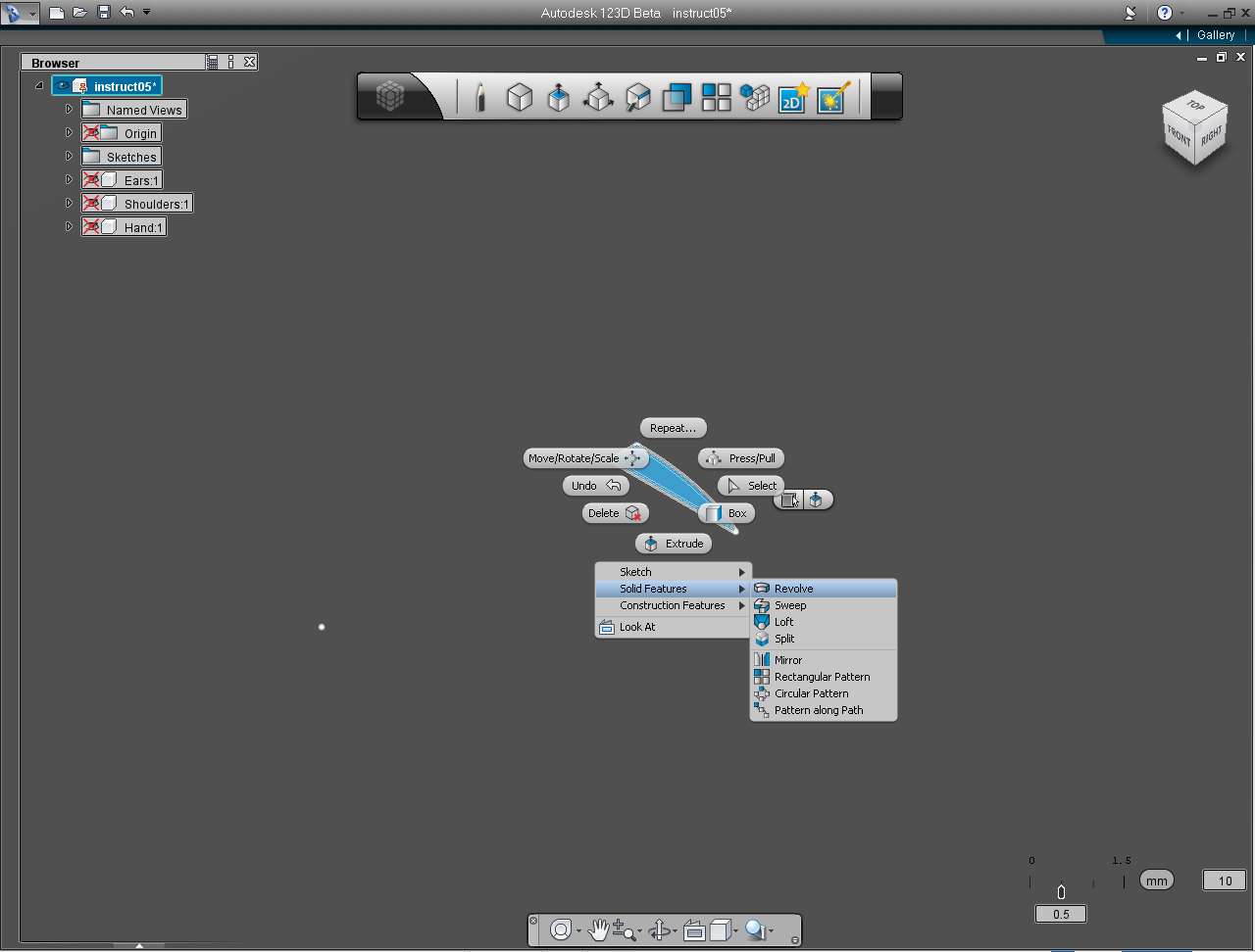
12. Now, we got the flat cross-section ready to "Revolve" into the eye lens. Right click at the the cross-section of the eye lens to bring up Marking Menu. And select "Solid Features" -> "Revolve"
13. Select short vertical line to be Revolving Axis.
14. Specify the "Full" revolution or type in 360 in the input box. Then, right click the mouse to bring up Marking Menu, and select "OK" to commit the command.
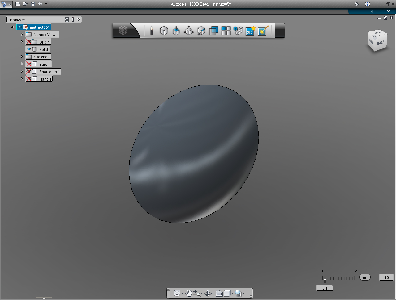
15. We got the lens! Use the "Orbit" tool from the "Navigation" Menu Bar to rotate the lens to the opposite direction, so we could see the back of it.
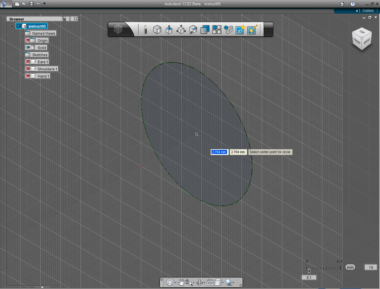
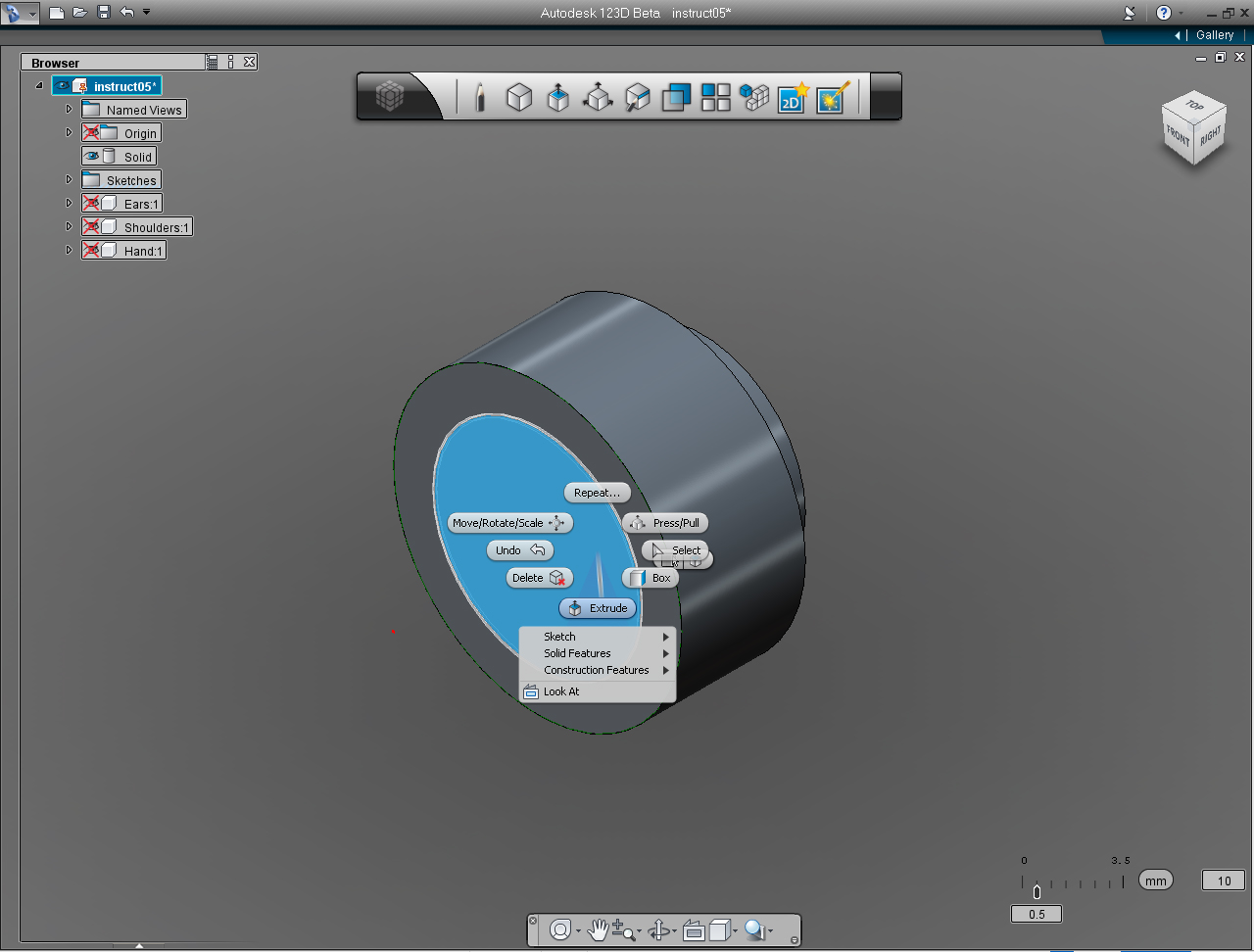
16. Select "Circle" pill in the "Sketch" Marking Menu
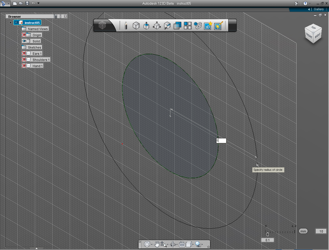
17. Move the mouse over the back plane of the Lens, then press Shift key to make the selected plane as the drawing plane. Then specify the cent point of the circle at 2.764, 2.764
18. Specify the radius of the circle to 5mm
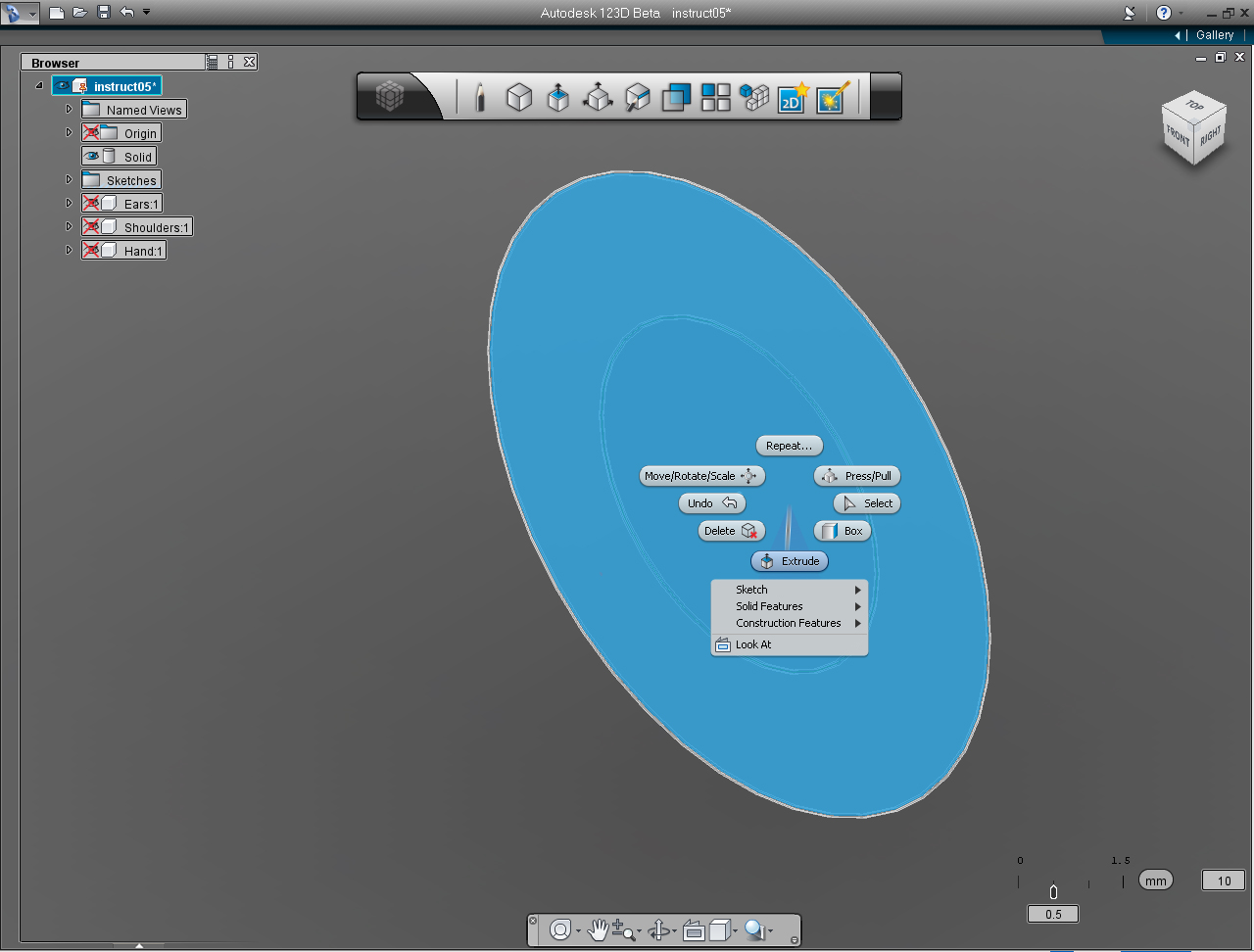
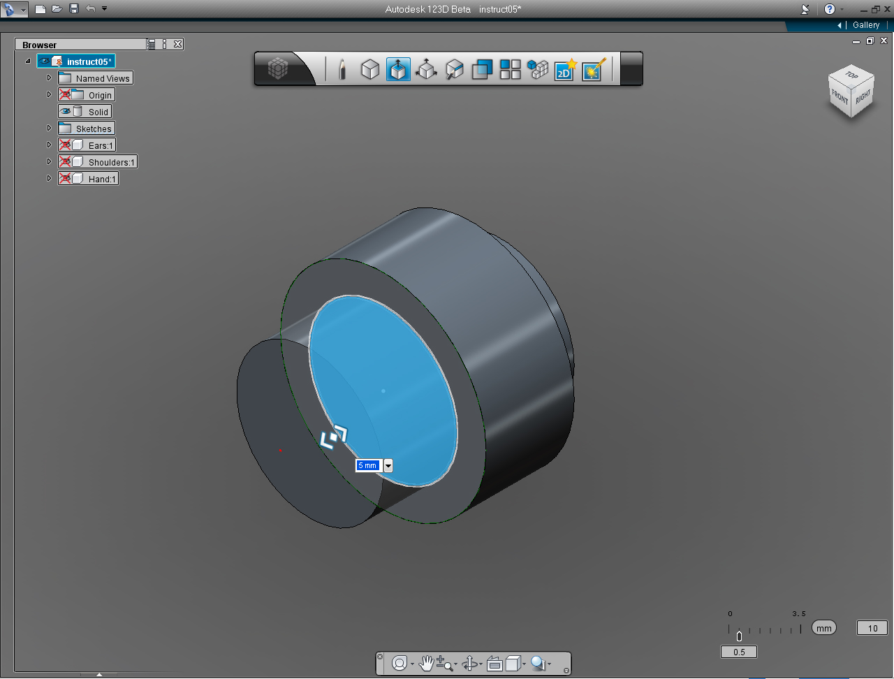
19. Right click at the newly created circle plane to bring up the Marking Menu, and select "Extrude" pill.
20. Drag bi-directional arrow or specify the height of the circle to 2mm.
21. Right click to bring up again the Marking Menu, click at "OK" pill to commit the command.
22. Use the "View Cube" (the edge between FRONT and RIGHT) to rotate the model around to see what we just have created.
Eyes: Part 2 - Eye
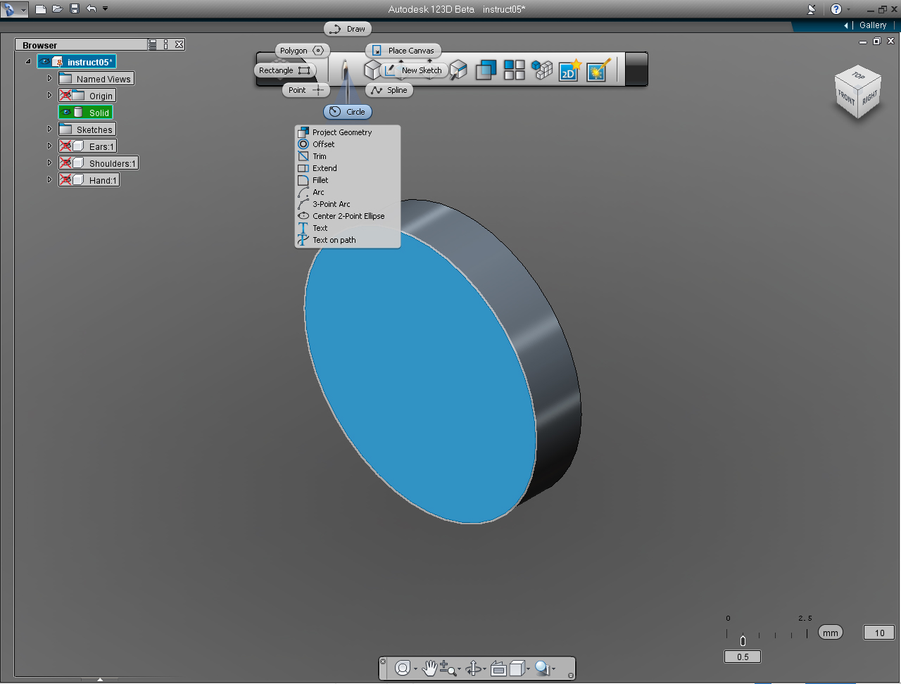
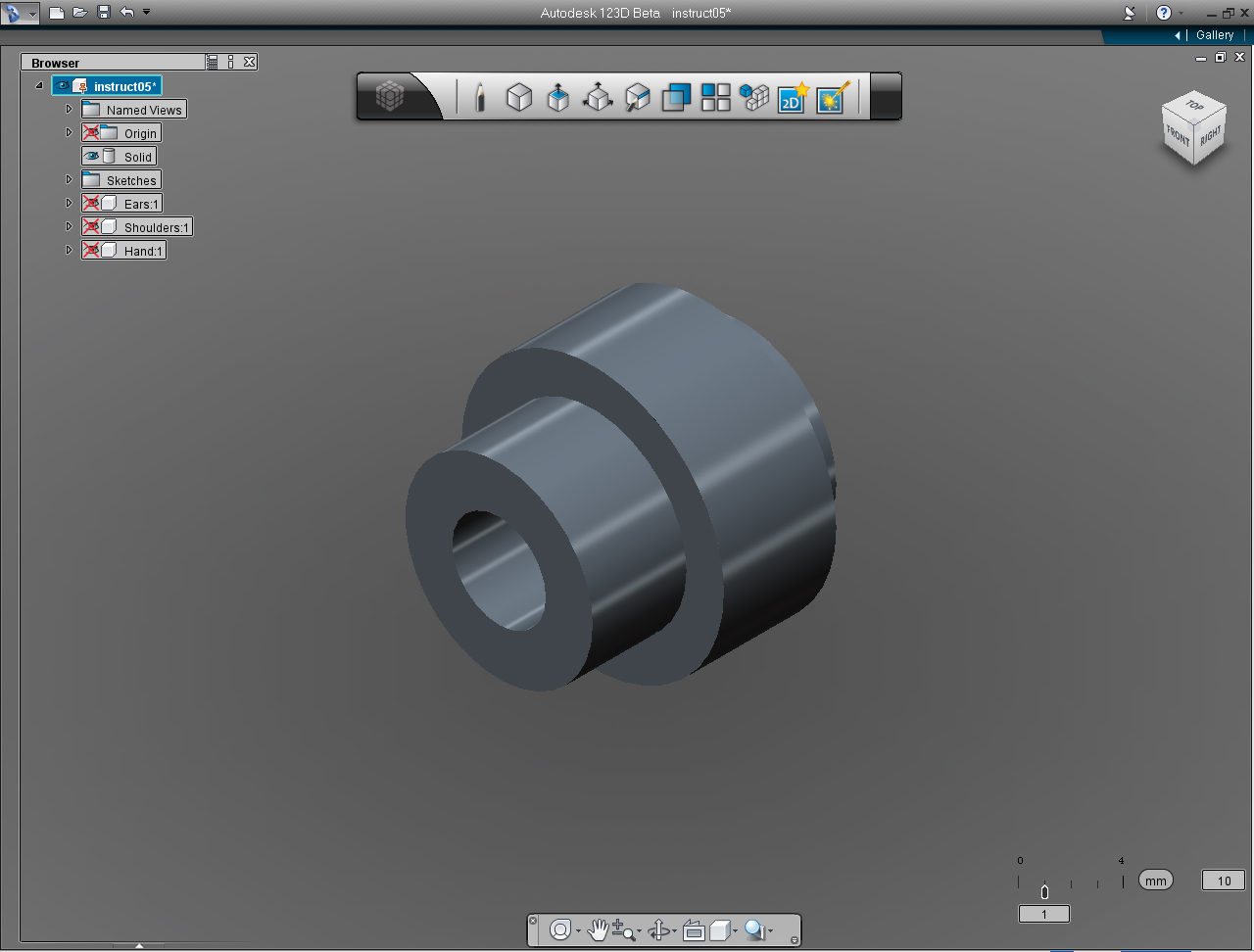
- "View Cube"
- "Circle" pill from "Sketch" Marking Menu
- "Extrude" pil from "Create" Marking Menu.
And these are the steps:
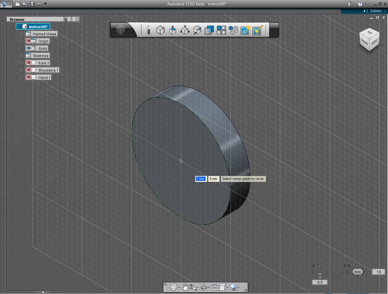
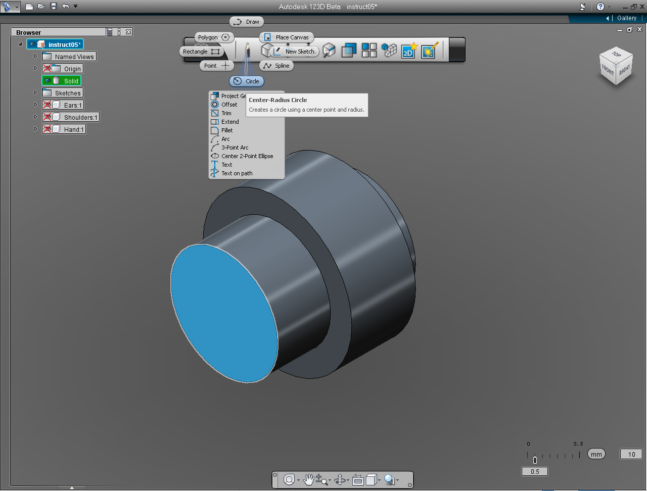
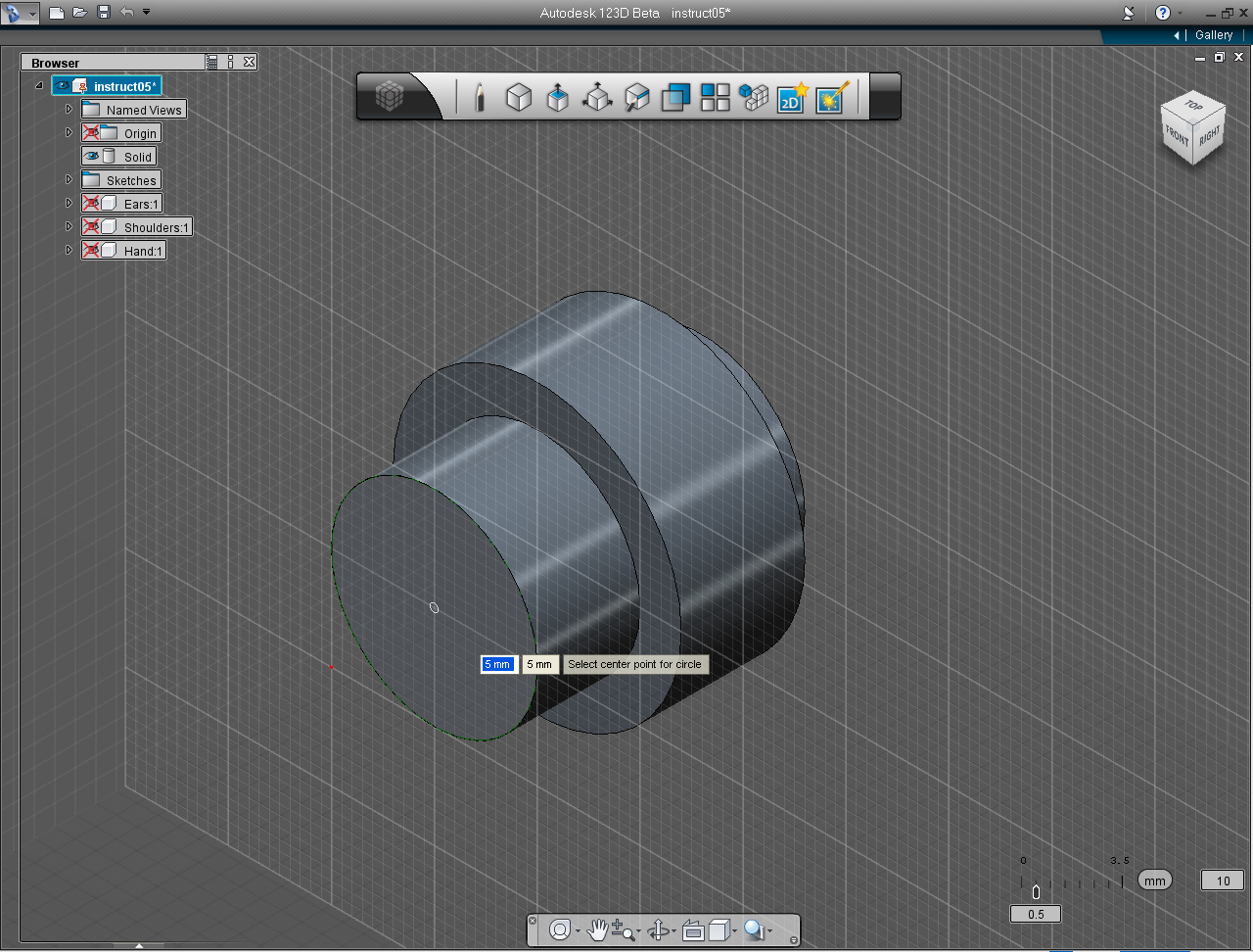
1. Use the "View Cube" to set the view to HOME. And select "Circle" pill from "Sketch" Marking Menu.
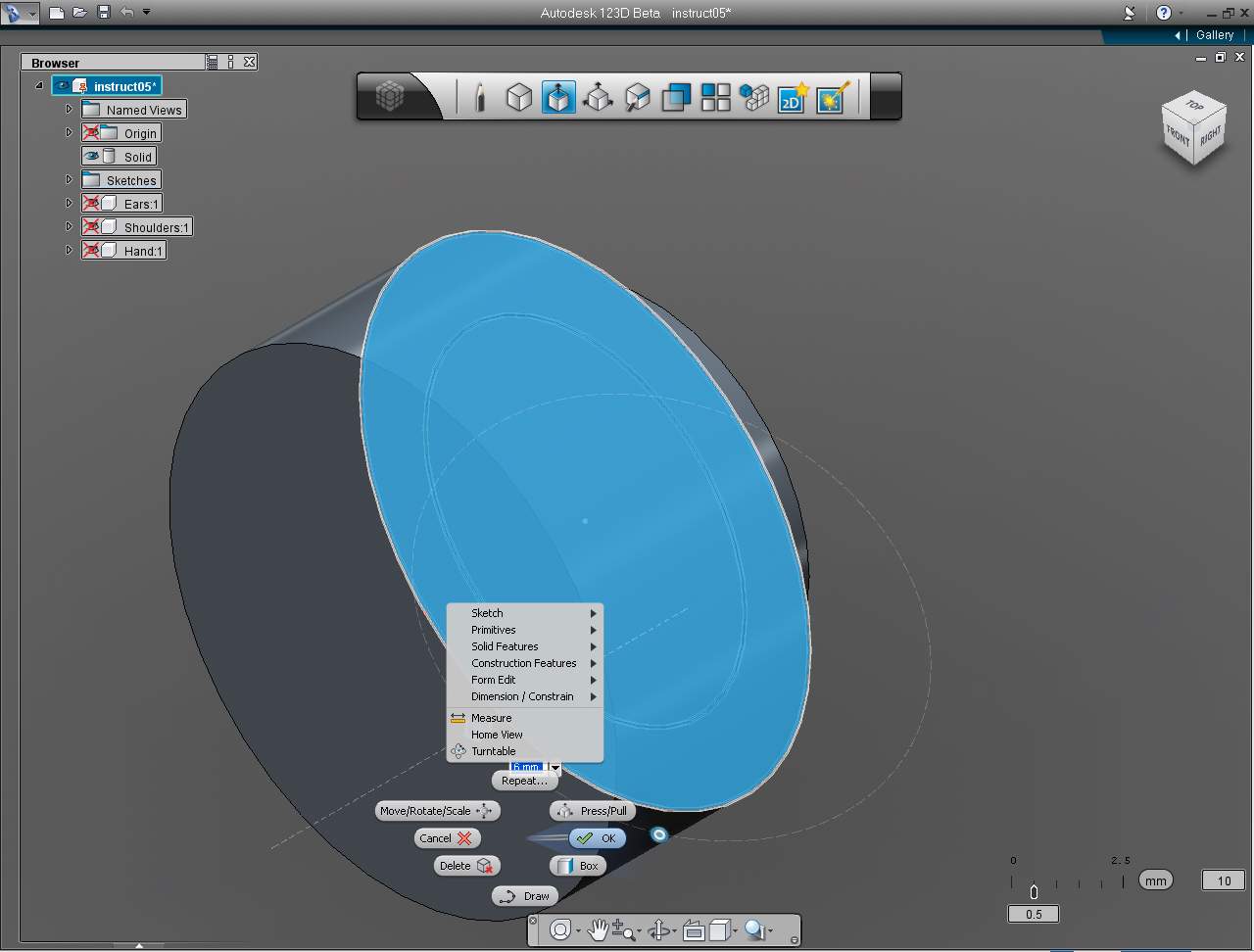
2. Move the cursor over the back plane of the Solid model, then press Shift key to make the back plane be the drawing plane. And specify the center point of circle at 5, 5mm.
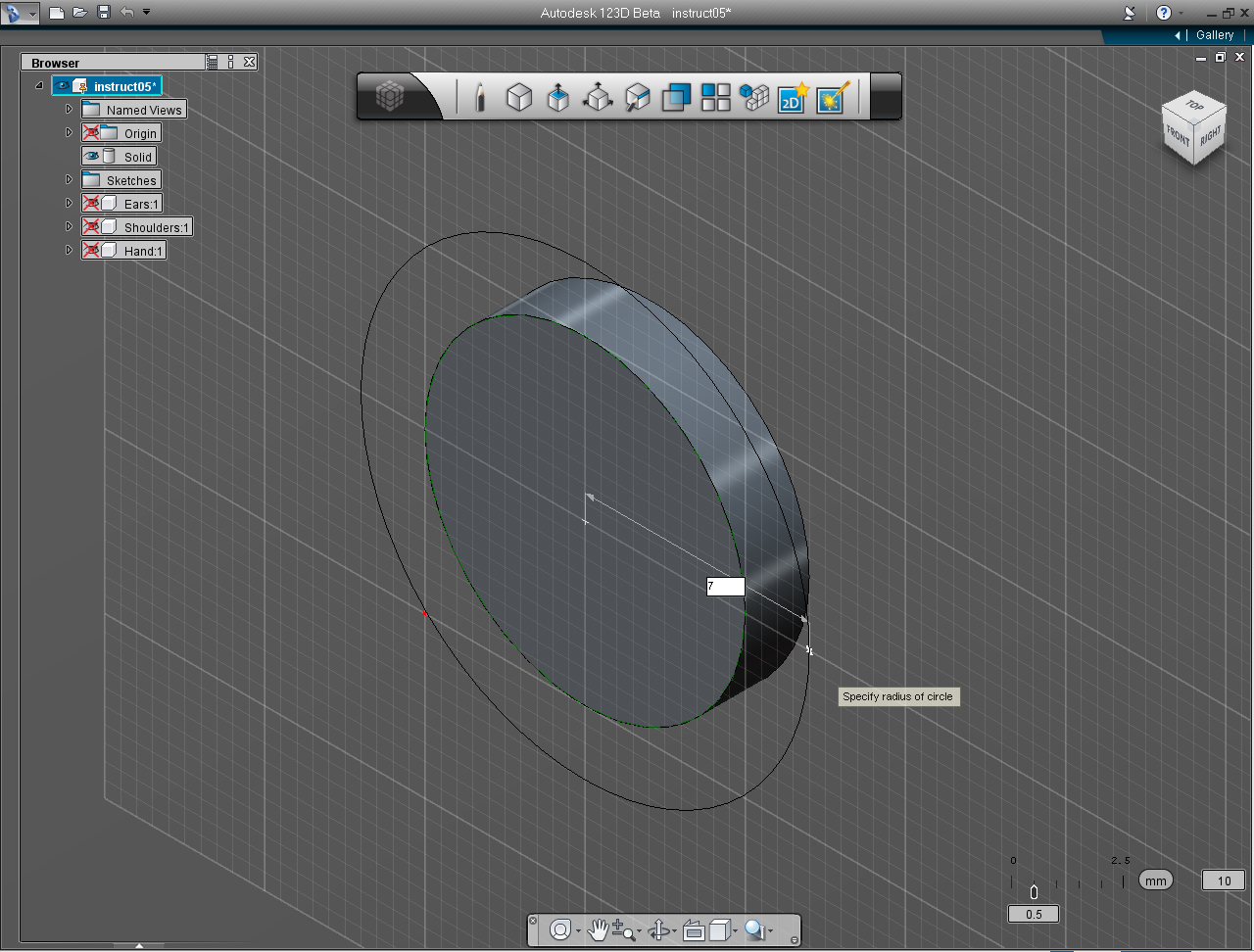
3. Specify the radius of the circle as 7
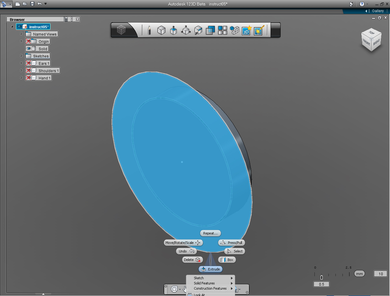
4. Bring up the Marking Menu by right click the mouse button. And select "Extrude" pill.
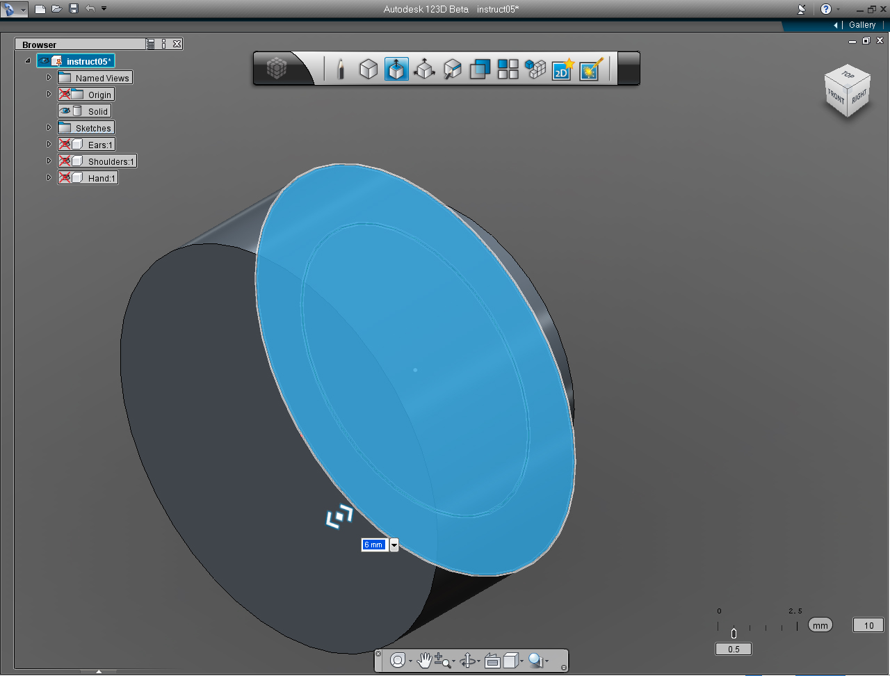
5. Specify the extrusion height of 6mm. Bring up the Marking Menu again to commit the command with the "OK" pill.
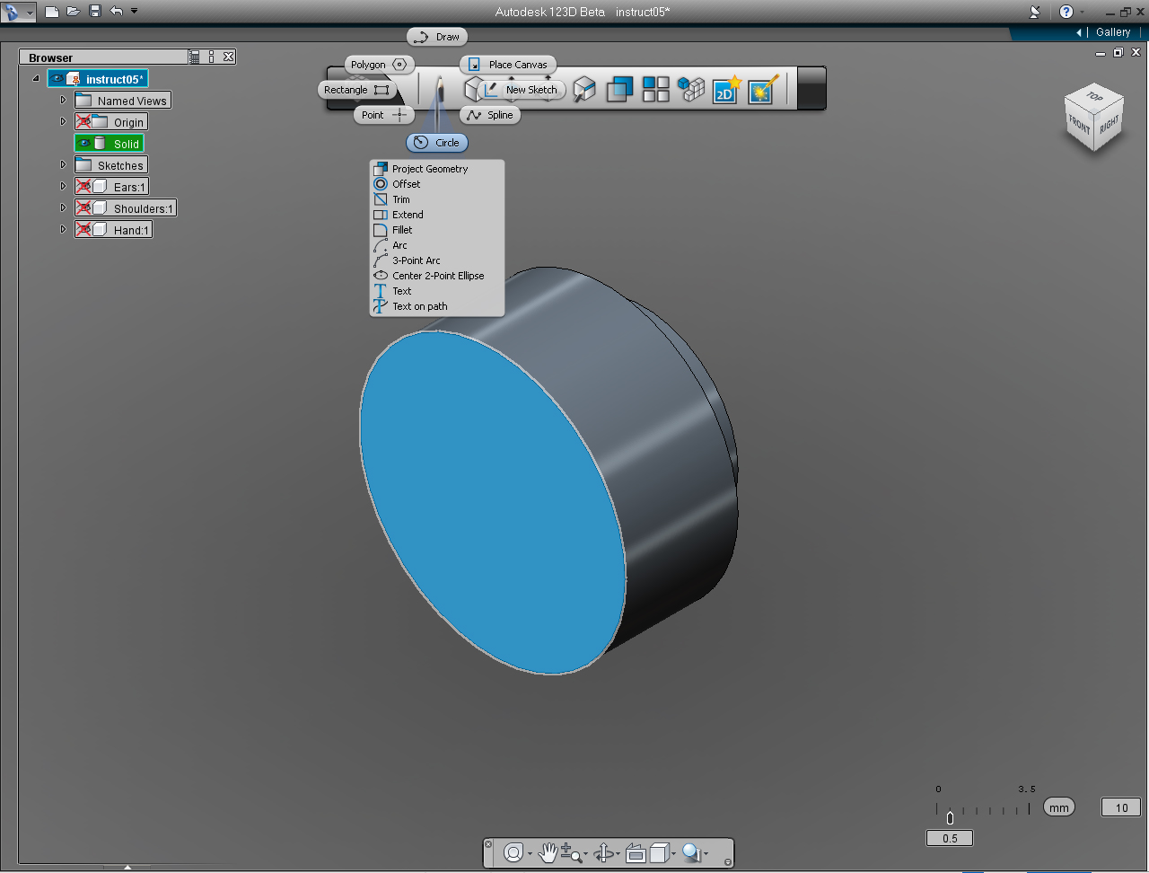
6. Create another extrude circle, Select "Circle" pill from "Sketch" Marking Menu.
7. Move the cursor over the back plane of the Solid model, then press Shift key to make the back plane be the drawing plane. And specify the center point of circle at 7, 7mm.
8. Specify the radius of the circle as 5mm
9. Bring up the Marking Menu by right click the mouse button. And select "Extrude" pill.
10. Specify the extrusion height of 5mm. Bring up the Marking Menu again to commit the command with the "OK" pill.
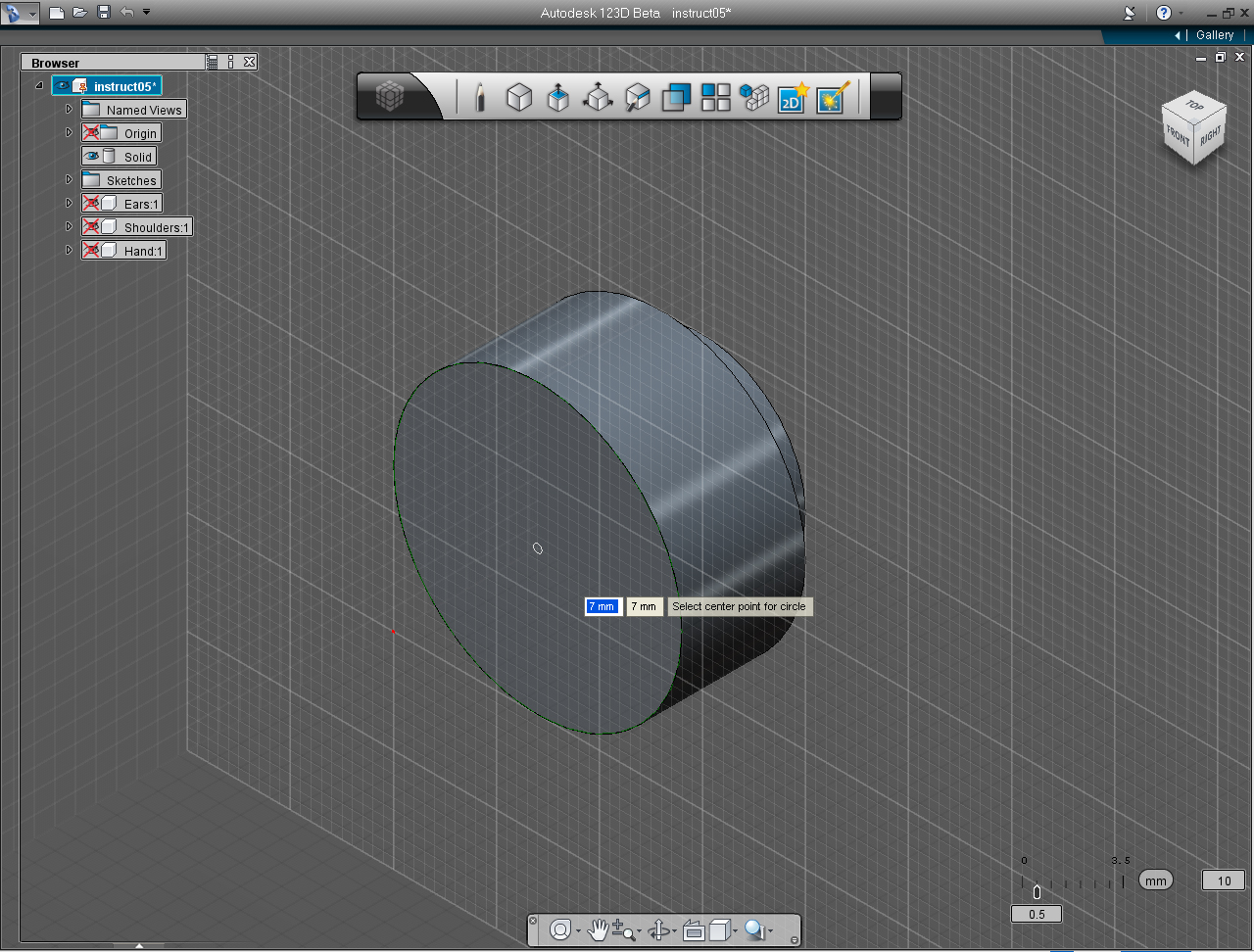
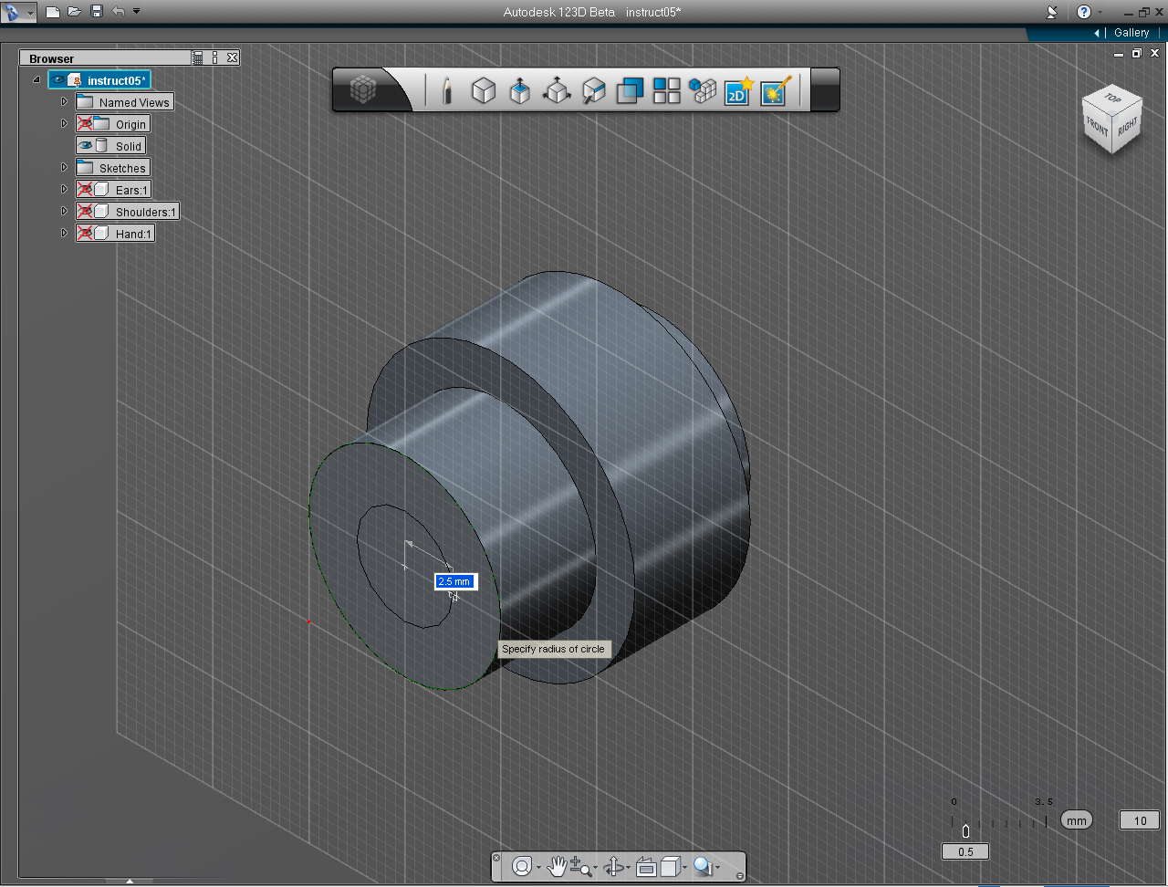
11. Create one more extrude circle, Select "Circle" pill from "Sketch" Marking Menu.
12. Move the cursor over the back plane of the Solid model, then press Shift key to make the back plane be the drawing plane. And specify the center point of circle at 7, 7mm.
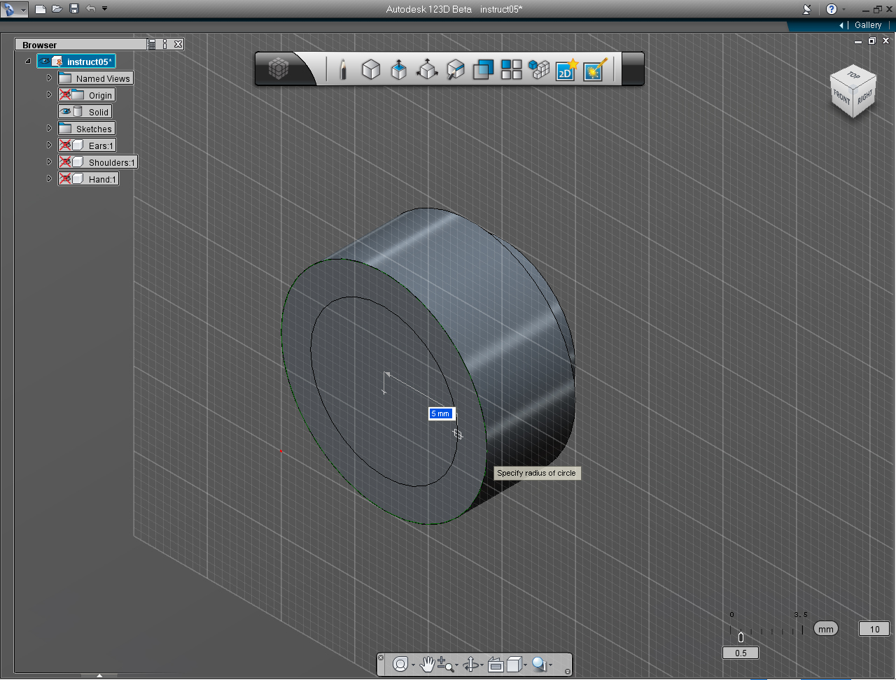
13. Specify the radius of the circle as 2.5mm
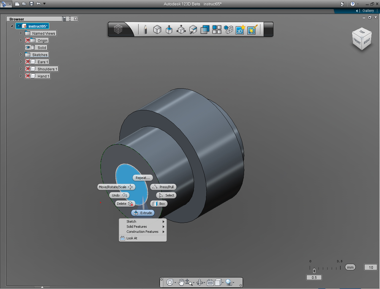
14. Bring up the Marking Menu by right click the mouse button. And select "Extrude" pill.
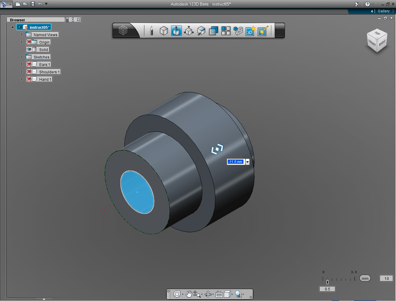
15. Specify the extrusion height of -11.5mm.
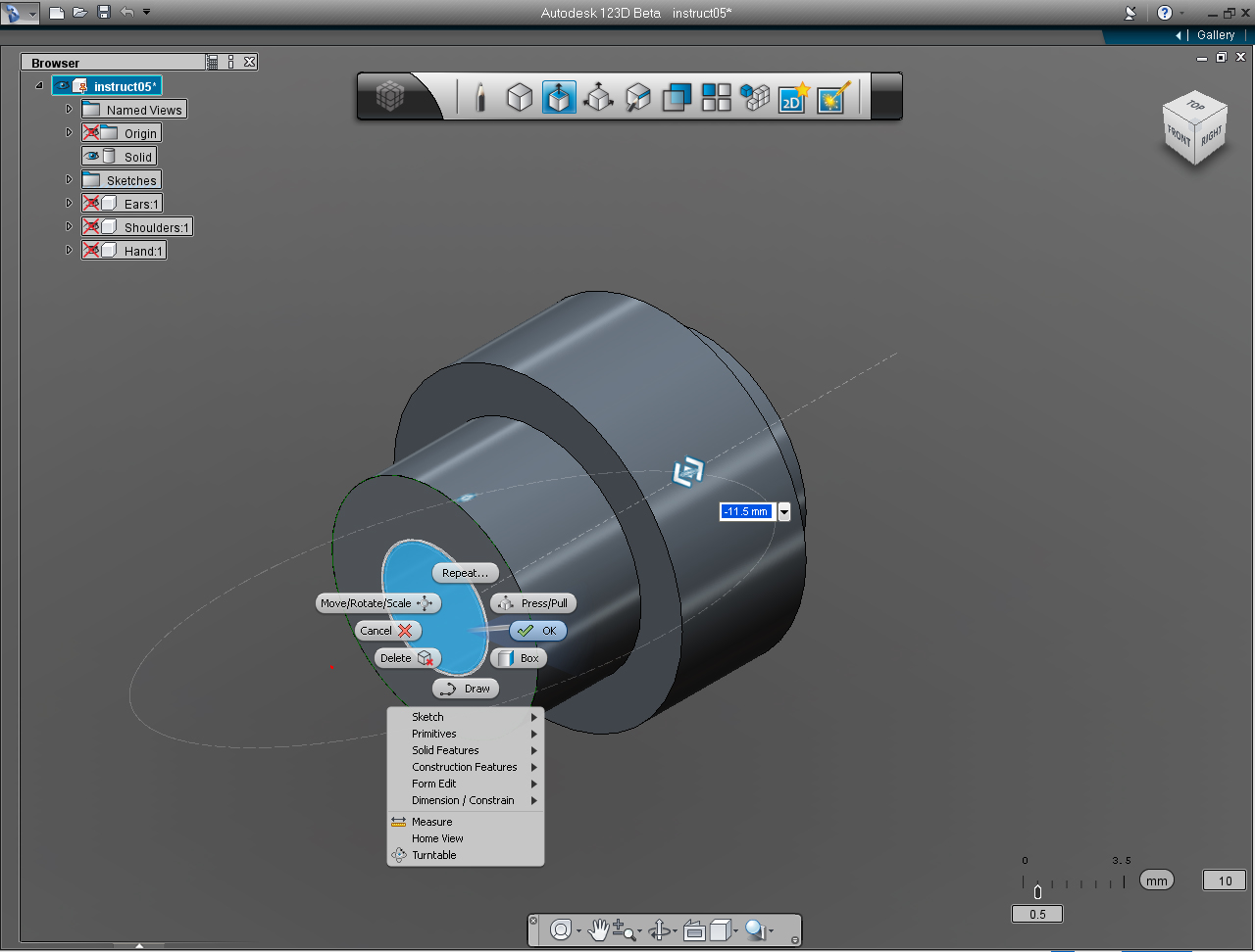
16. Bring up the Marking Menu again to commit the command with the "OK" pill.
17. Voila! We got the eye with the hole made ready for the 5mm diameter LED.
Eyes: Part 3 - Left and Right Eyes
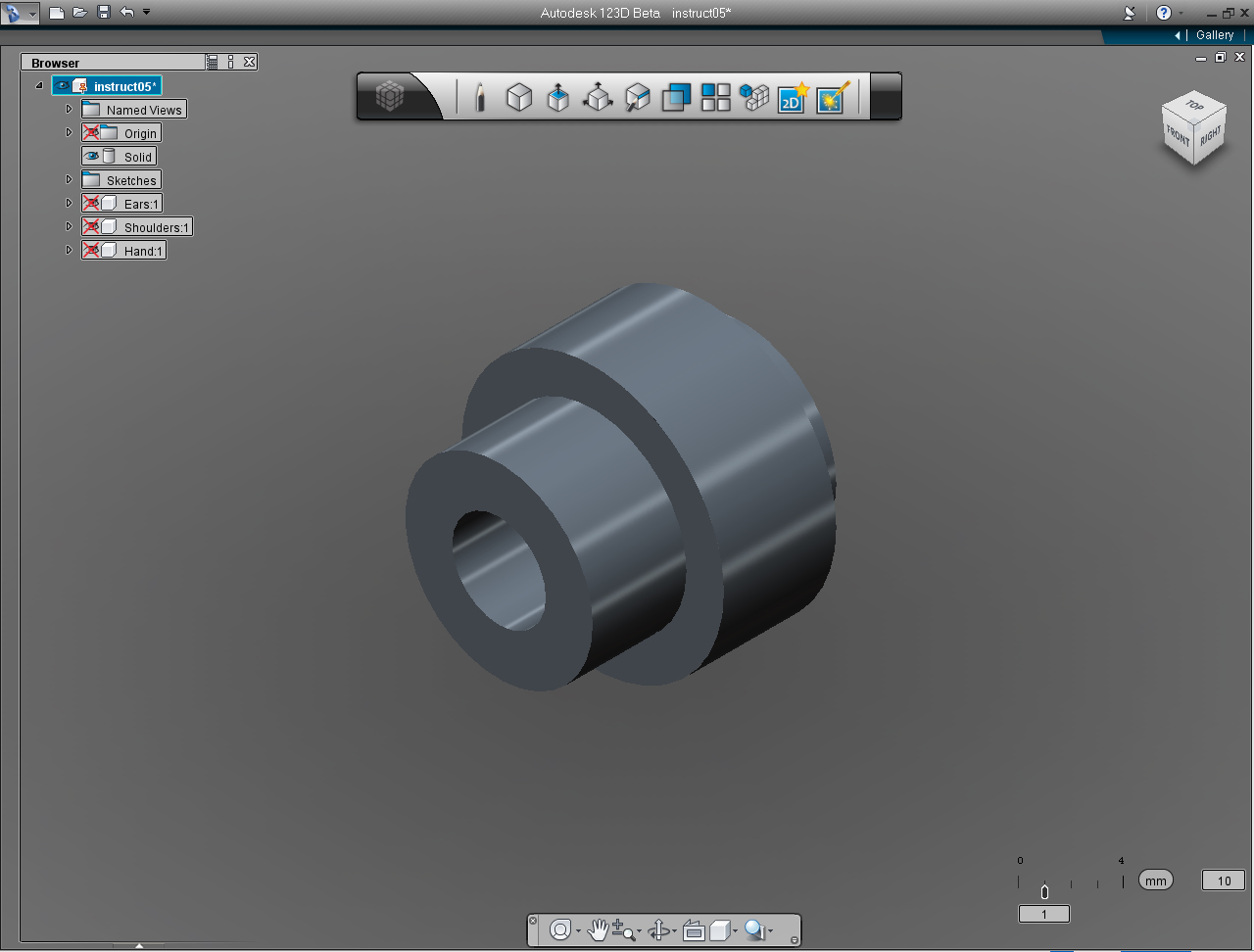
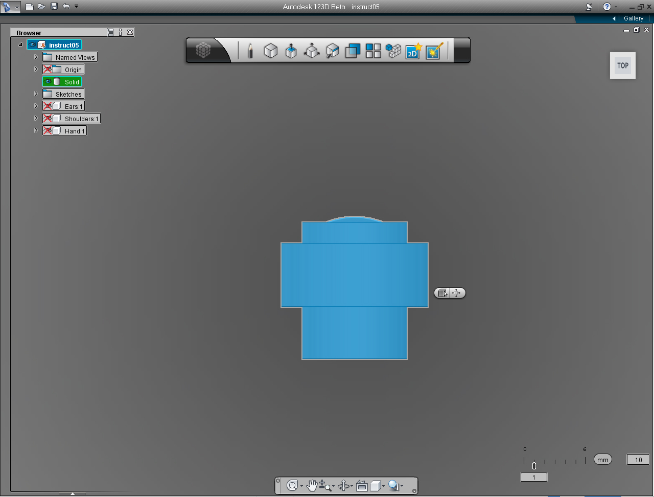
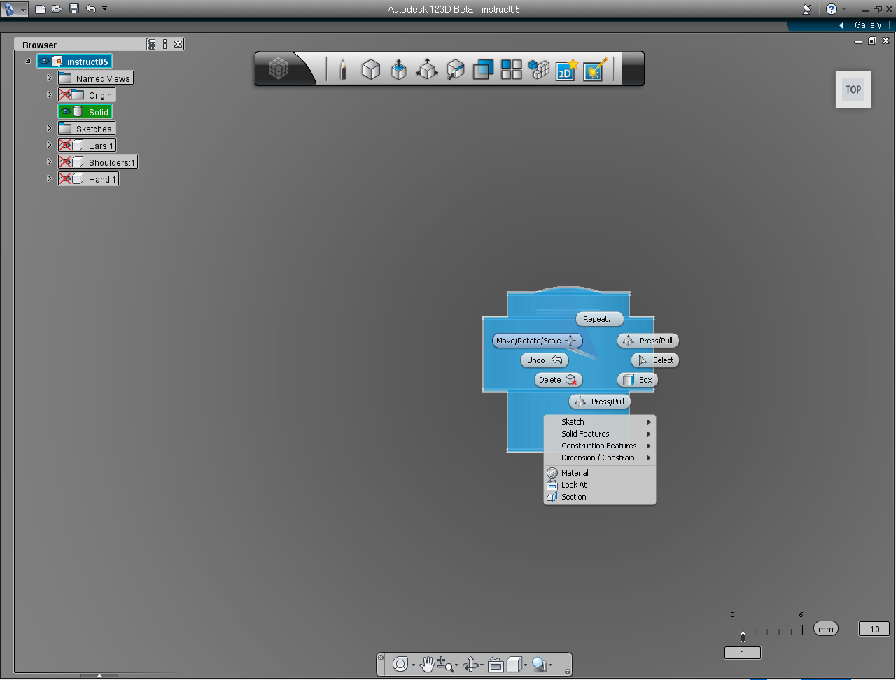
- "View Cube"
- "Move/Rotate/Scale" pill menu
- "Mirror" function in the "Pattern" Marking Menu
- "New Component" function in the "Feature Browser" Menu
- "Copy" function in the "Feature Browser" Menu
- "Paste" function in the "Feature Browser" Menu
- "Delete" function in the "Feature Browser" Menu
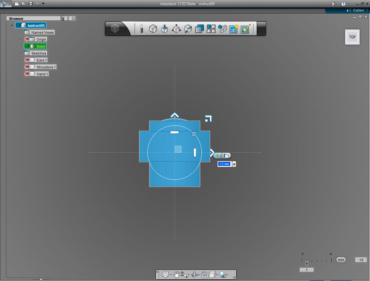
And these are the steps:
1. Set "View Cube" to TOP plane.
2. Highlight solid model of the eye.
3. Right click on the ear model to bring up Marking Menu. Then select "Move/Rotate/Scale" pill.
4. "Move, Rotate, Scale" Menu show up. Drag the "Right" direction arrow to the left, or enter value of -14.0 into the keyboard input box.
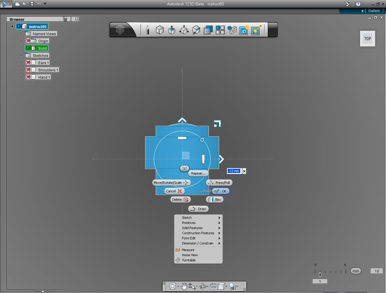
5. Right click to bring the Marking Menu, then select "OK" pill to commit the command.
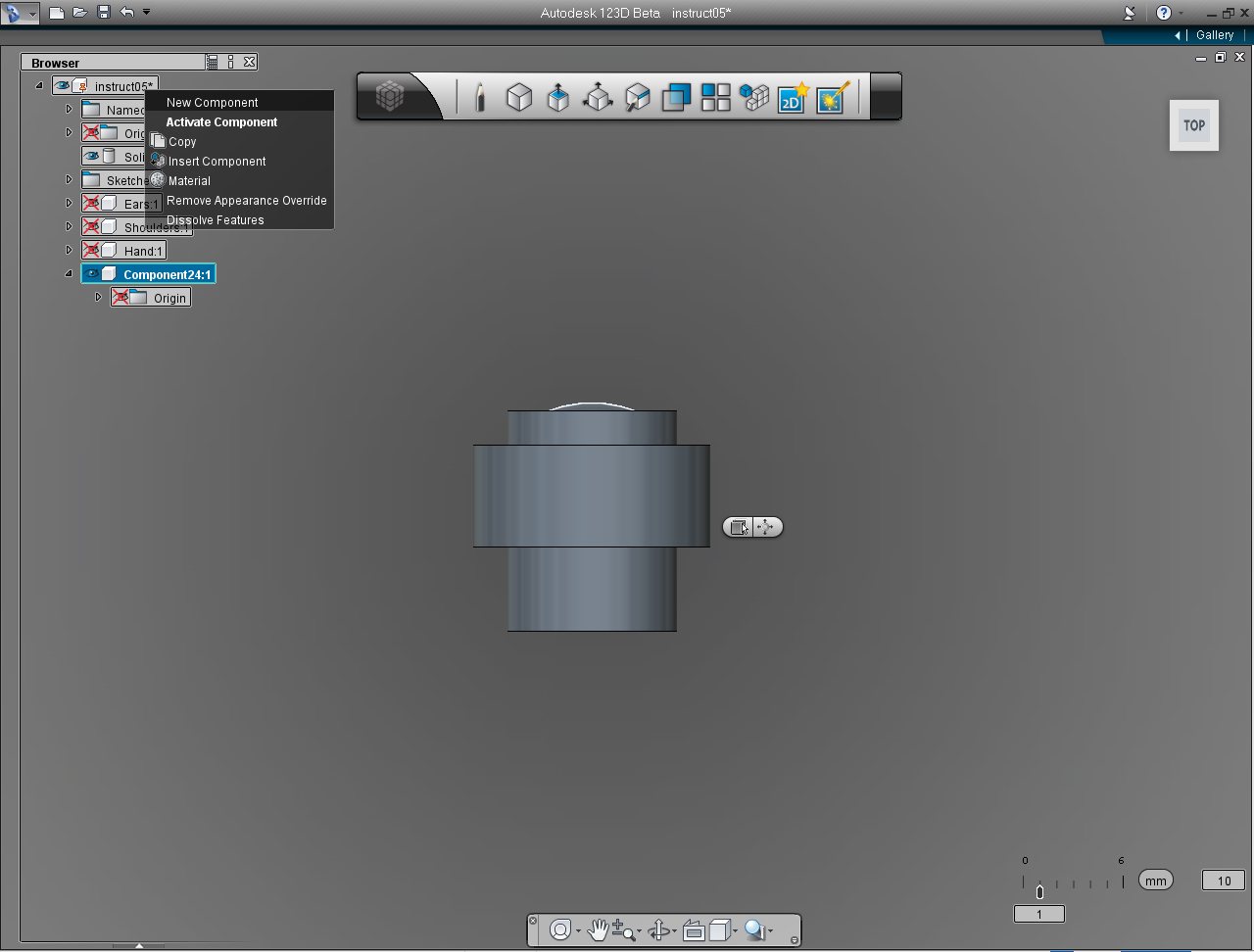
6. Create "New Component" on the "Feature Browser" menu. (Right click on the first item, then select "New Component")
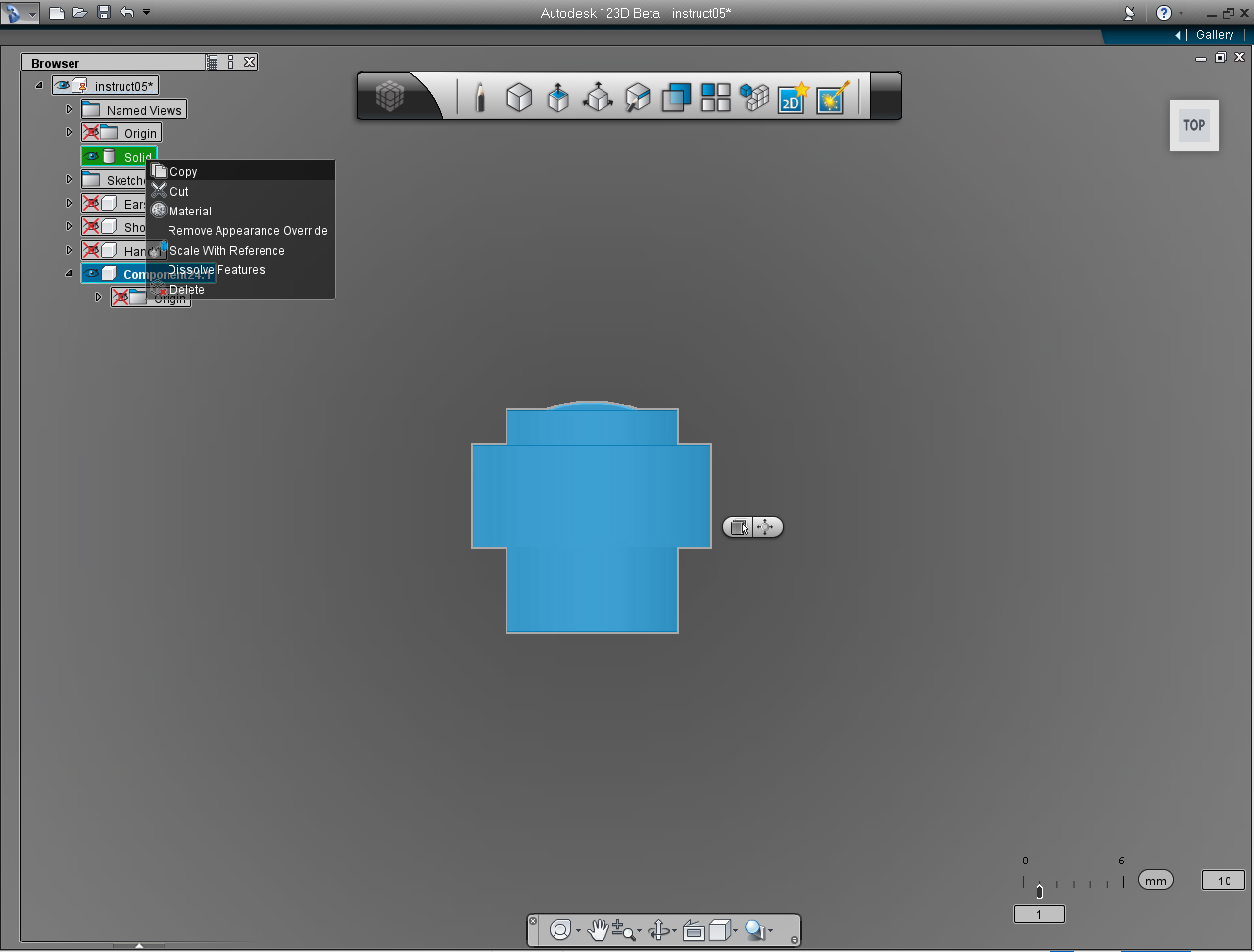
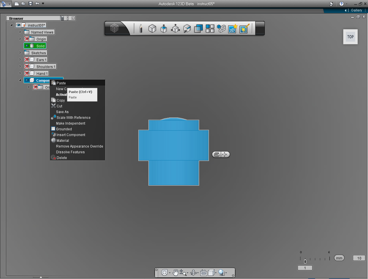
7. Left click at "Solid" to highlight the model. And Right click to bring up the commands list. Select "Copy"
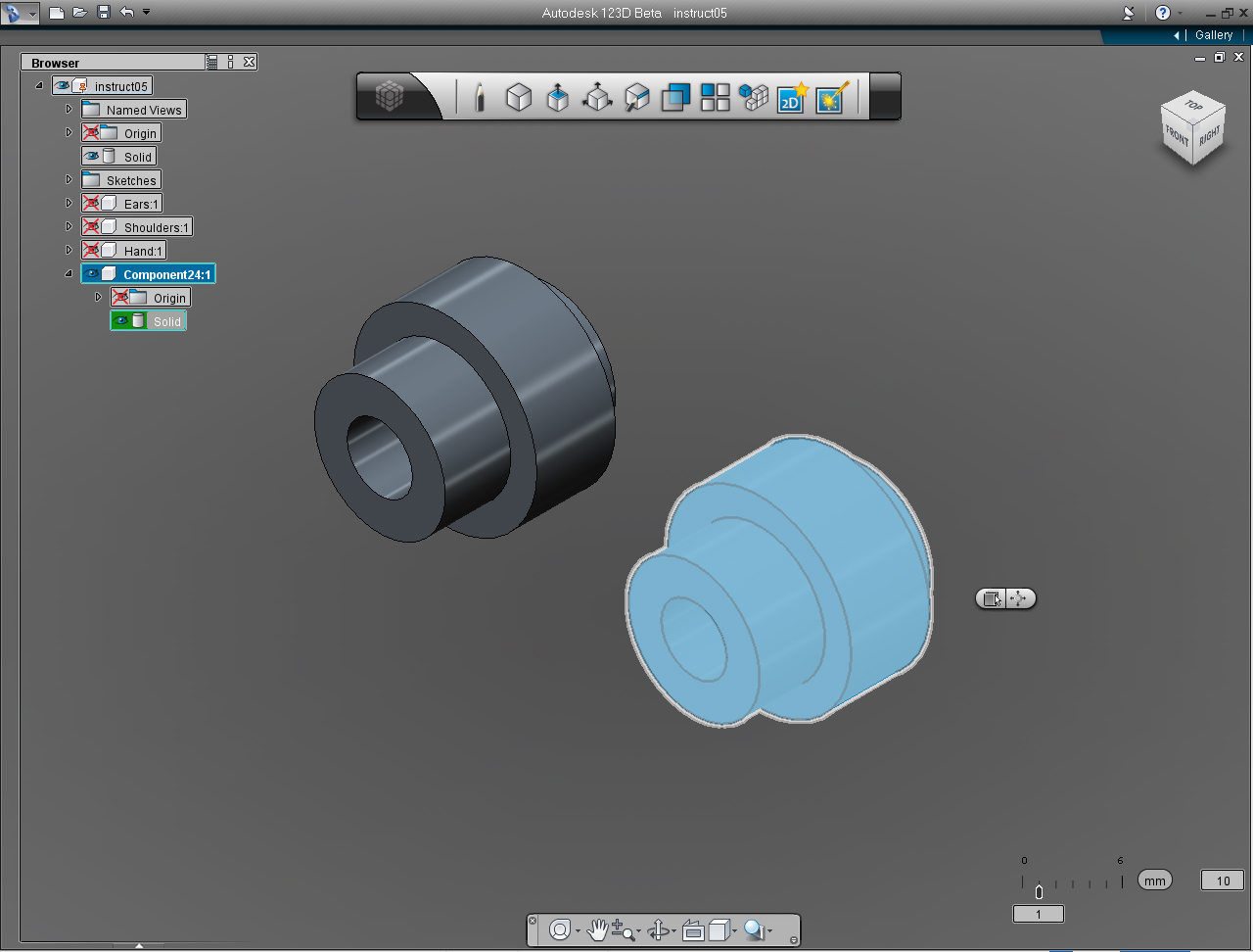
8. Now, left click at new "Component" we just created. And right click to bring up commands list. Then select "Paste"
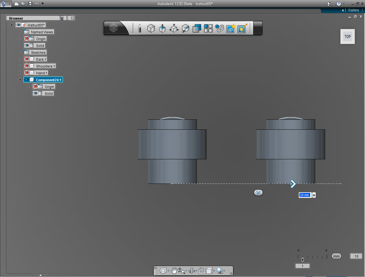
9. Drag the bi-directional arrow (or use keyboard input) to 24 mm. Right click to bring up Marking Menu again and select "OK" pill to commit the command.
10. Change "View Cube" to Home View.
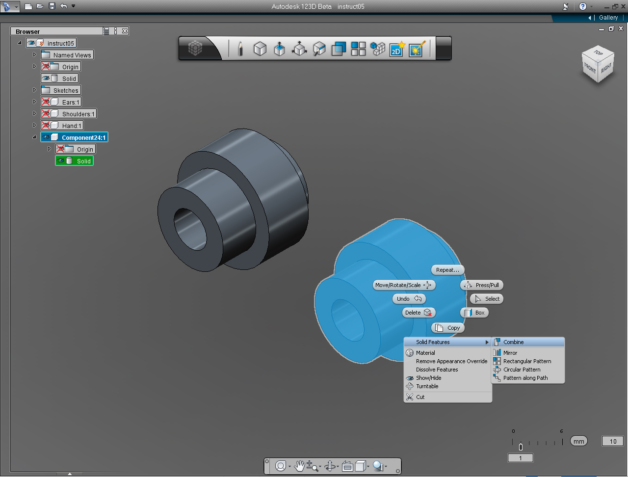
11. Select the right eye Solid model.
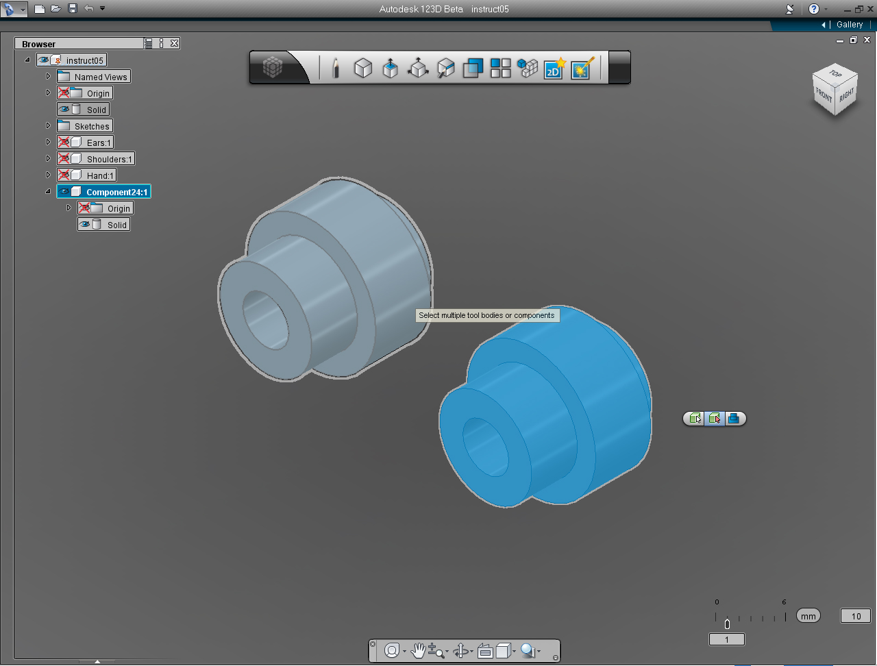
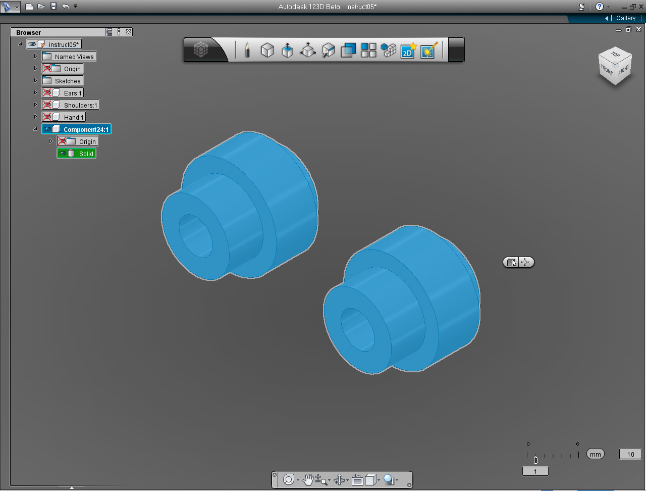
12. Right click to bring up the Marking menu, and select "Solid Features" -> "Combine"
13. Select the solid model of the left eye to combine the eyes Solid model together.
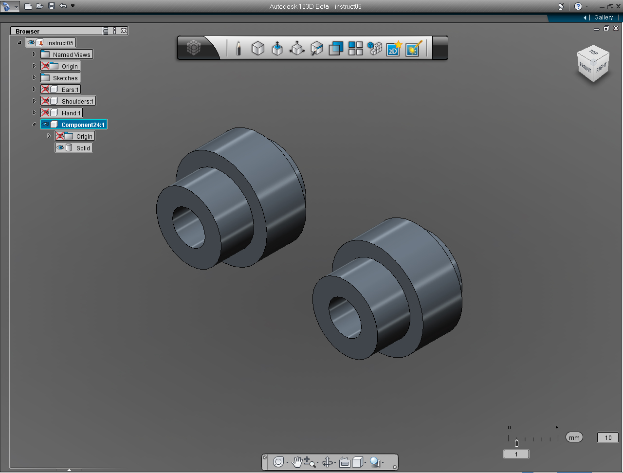
14. Now we got both eyes!
Save the file before moving on to the next Step!
Eyes: Part 4 - Eyebrows
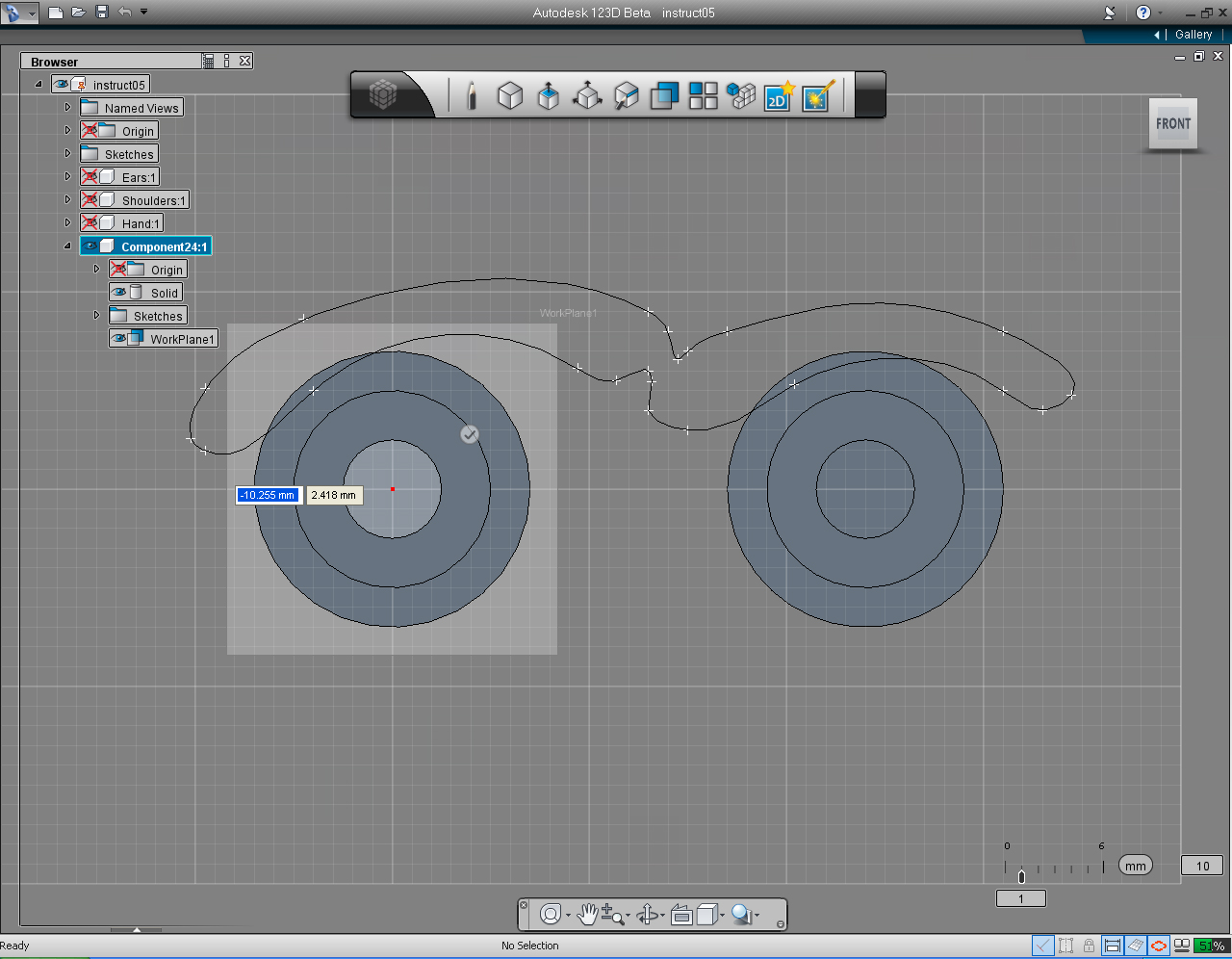
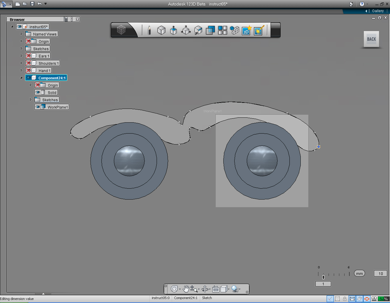
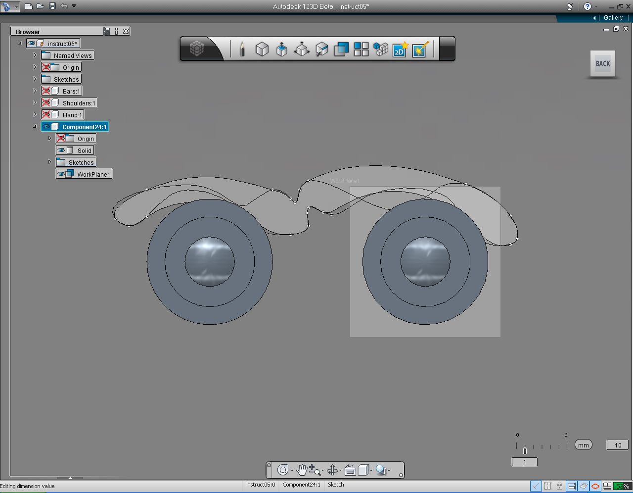
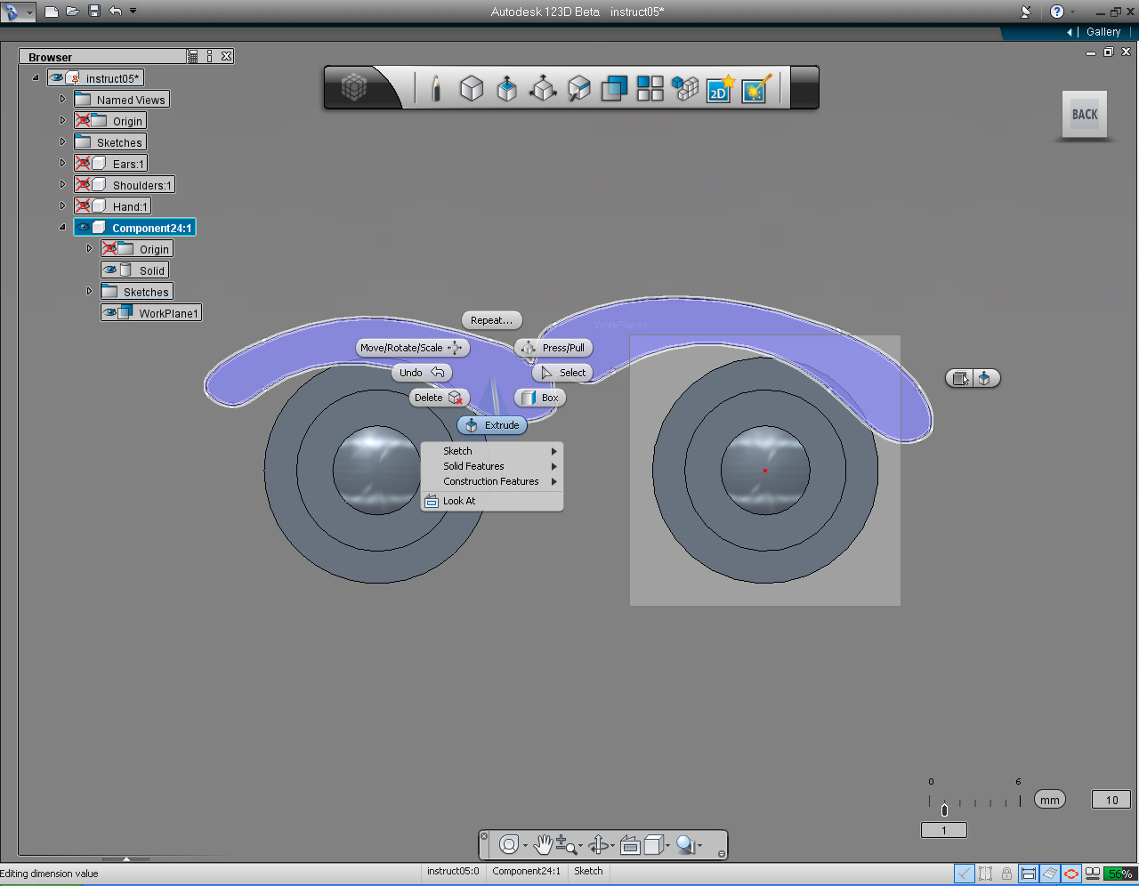
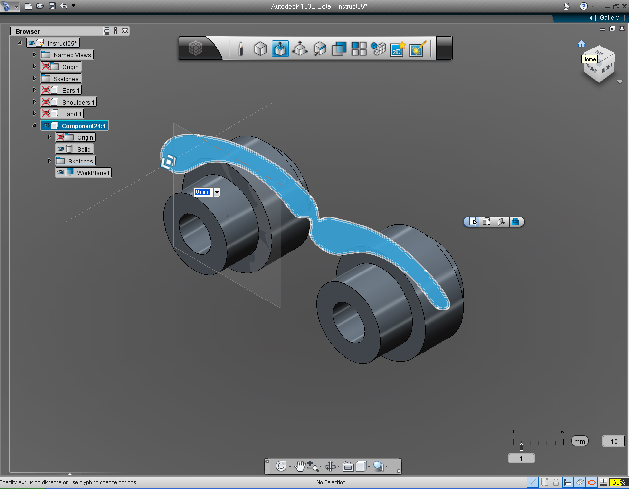
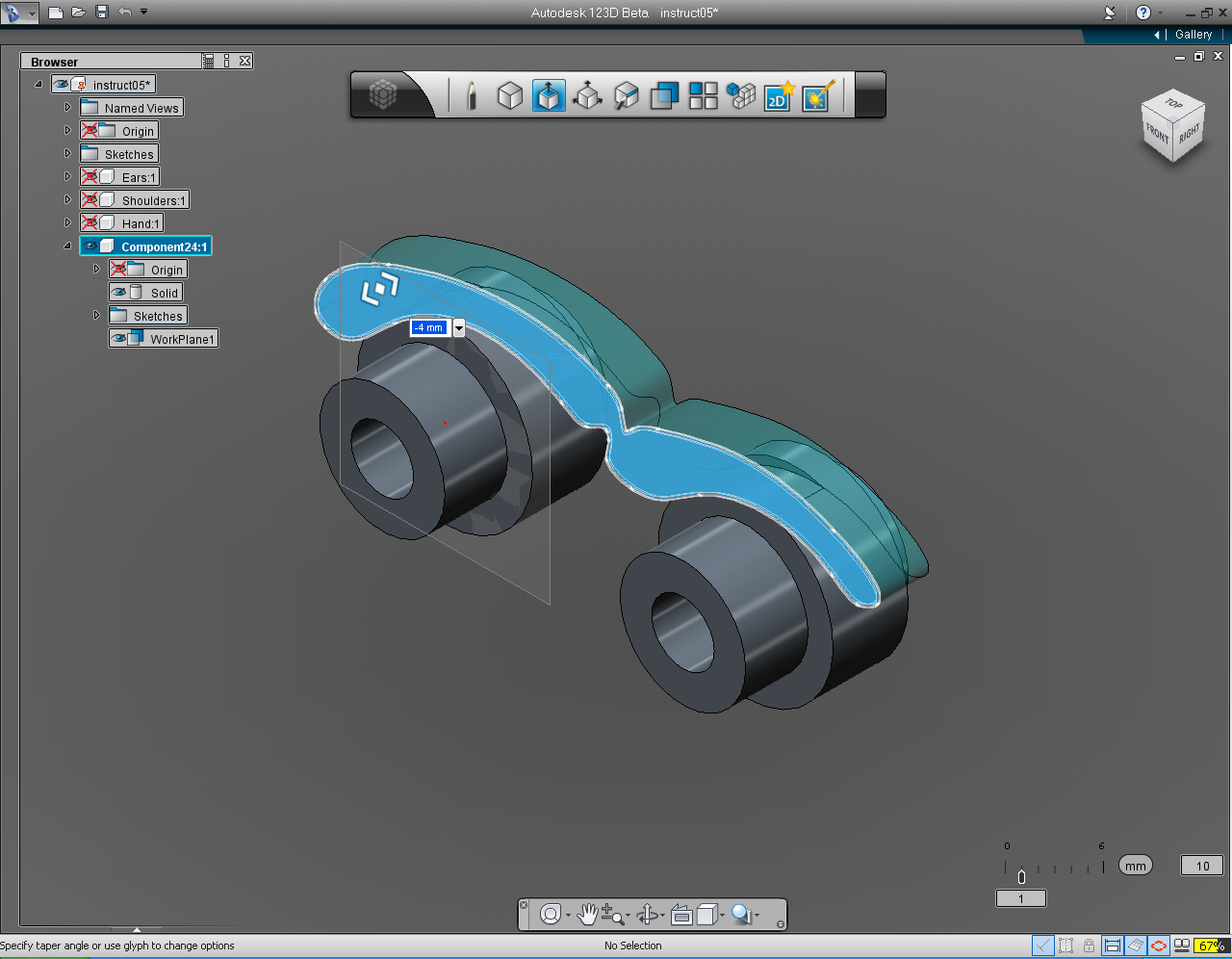
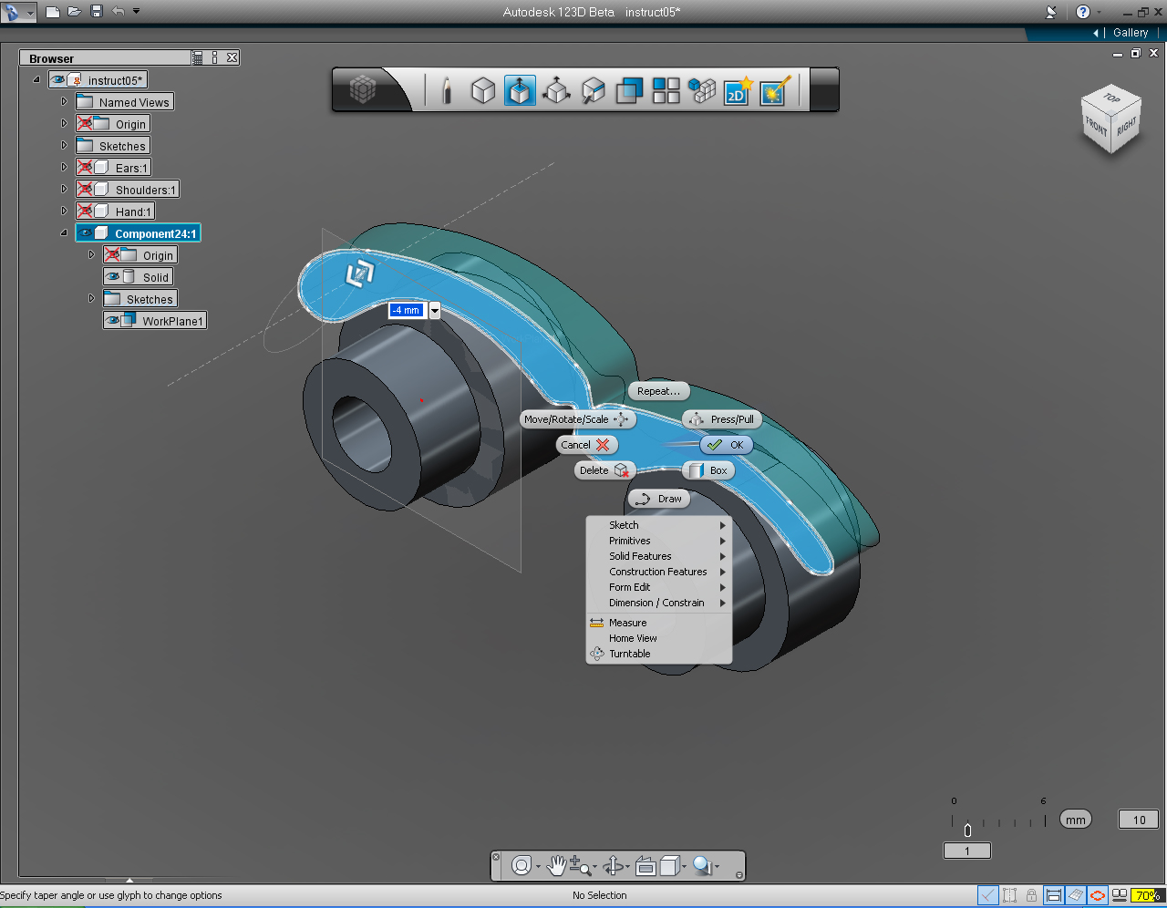
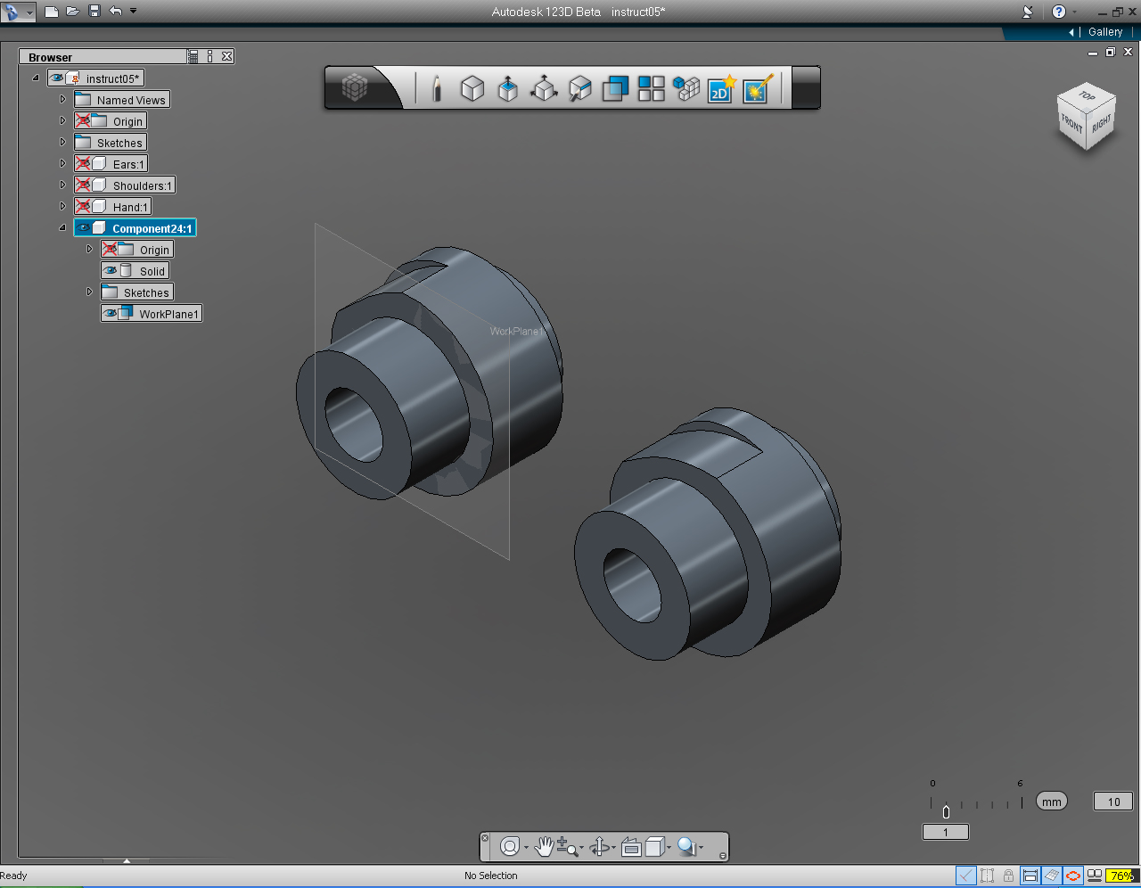
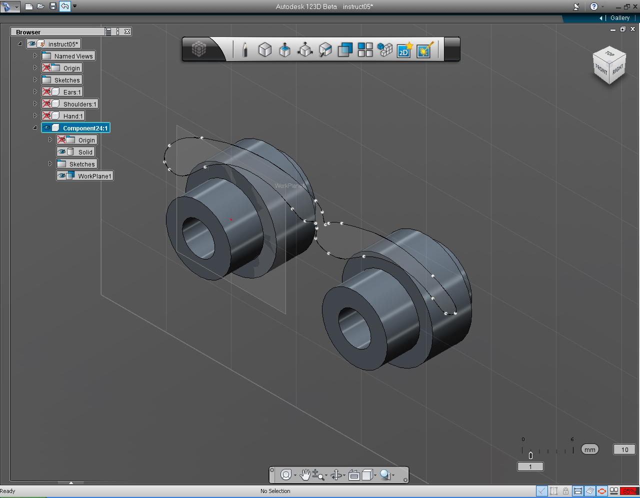
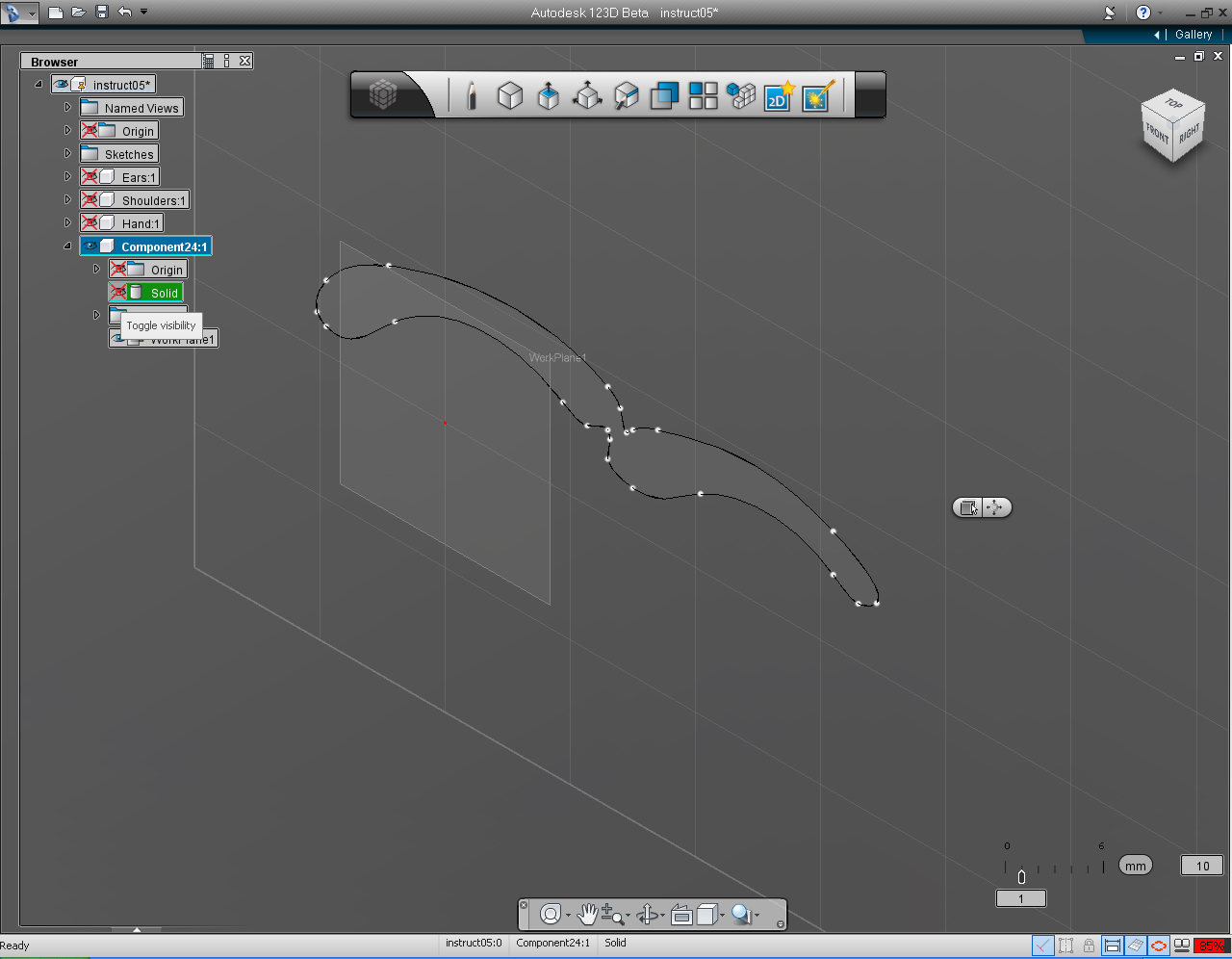
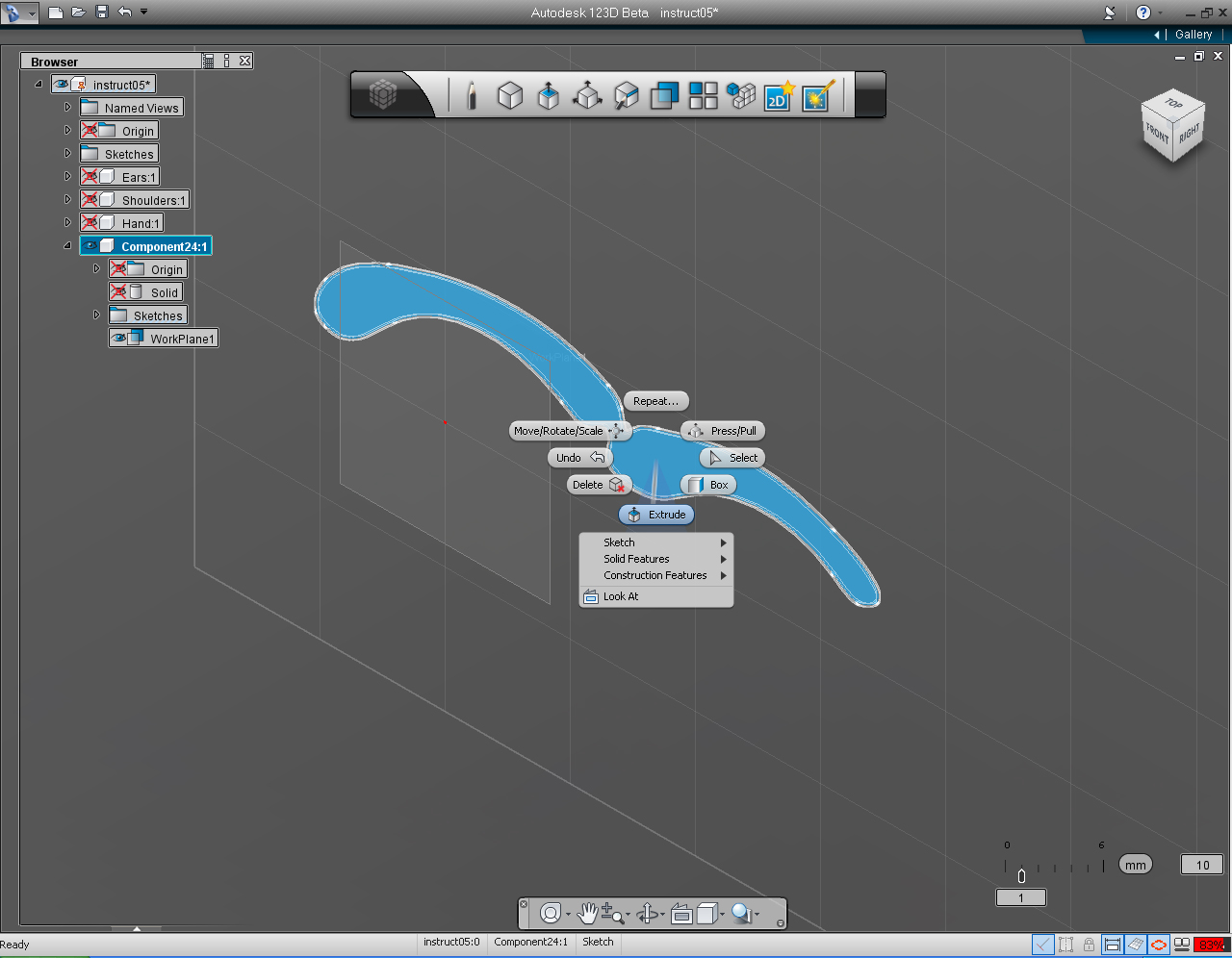
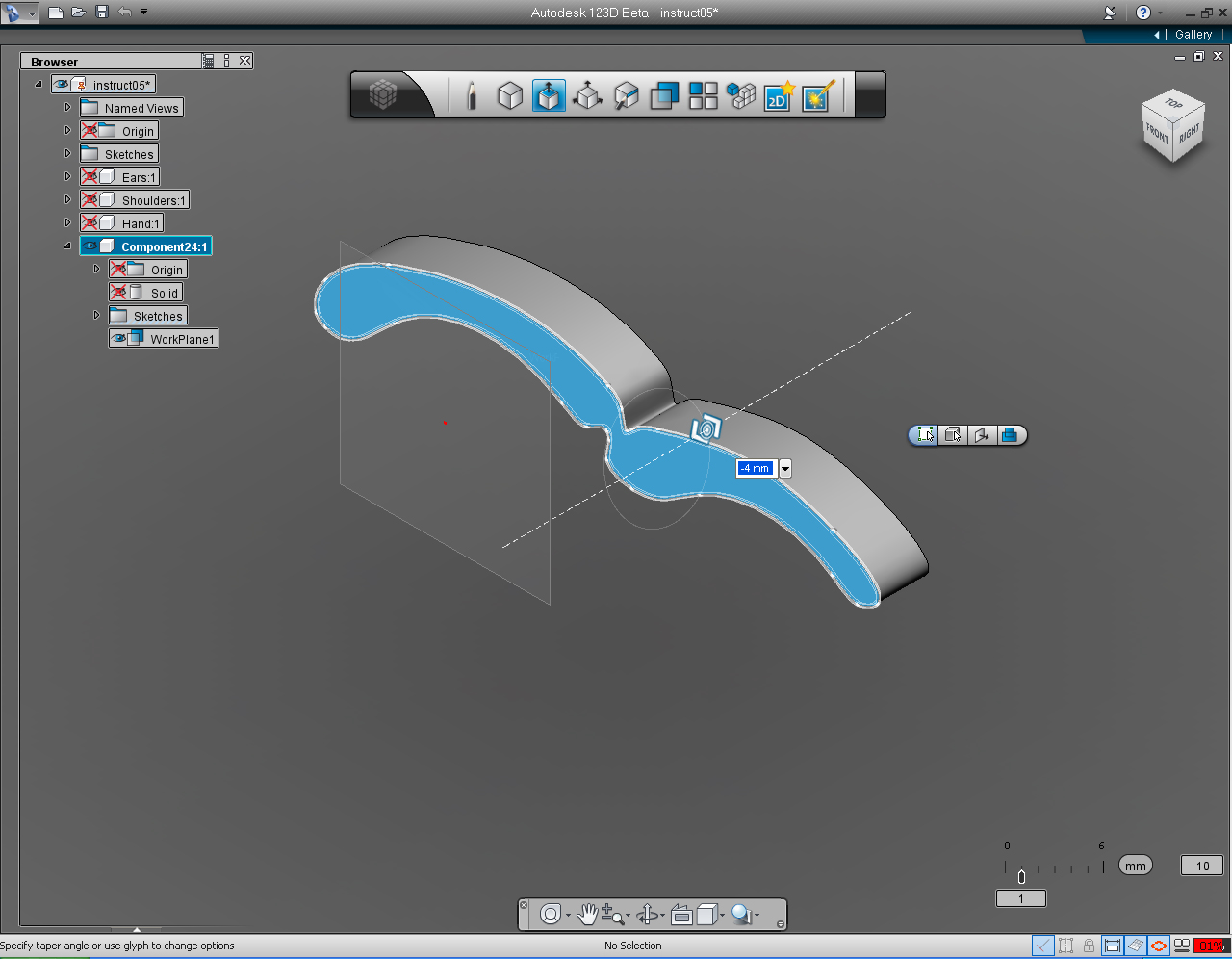
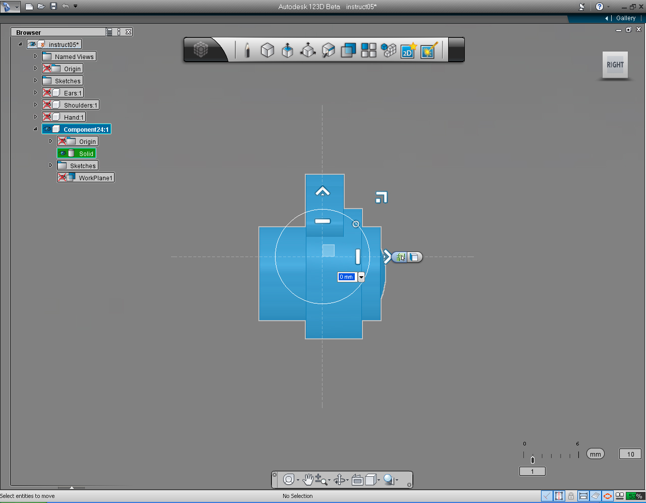
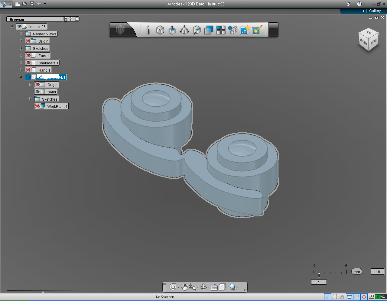
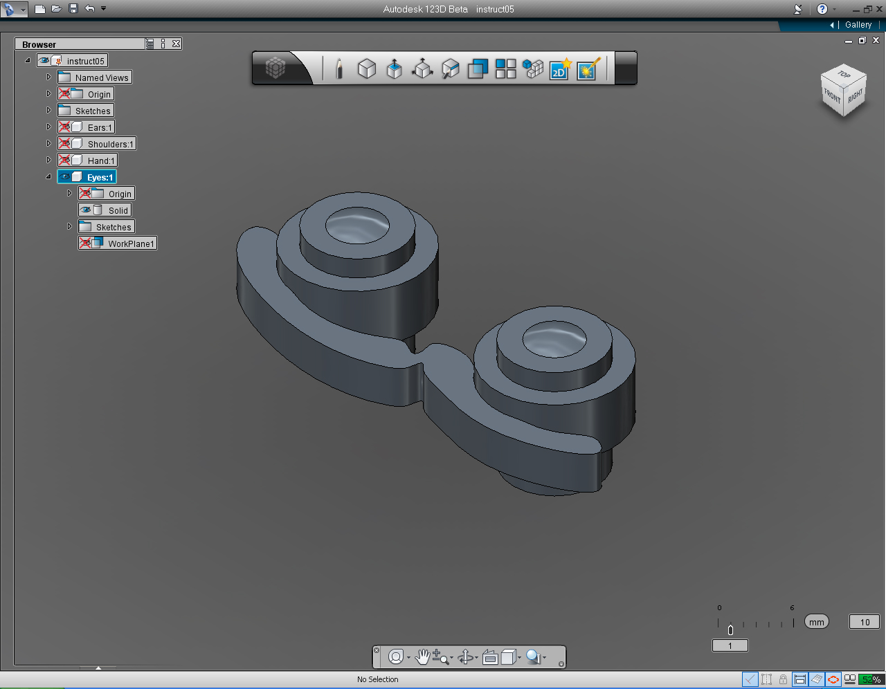
Summary of the commands to use in this Step:
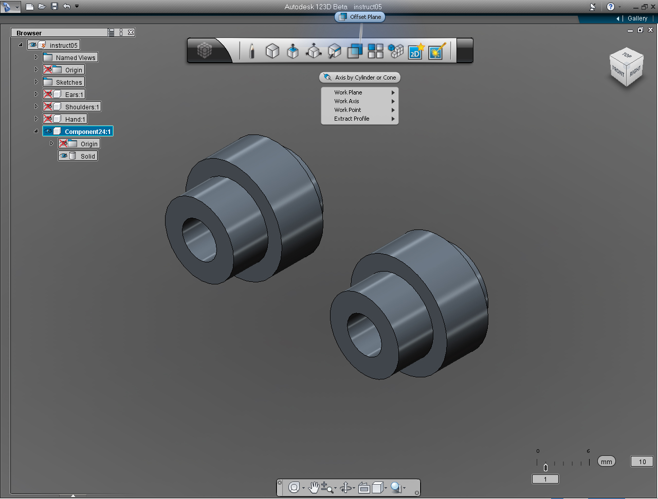
- "Offset Plane" pill in "Construction" Marking Menu
- "Spline" from "Sketch" Marking Menu
- "Extrude" from "Create" Marking Menu
- "Combine"
- "Move/Rotate/Scale" pill menu
And these are the steps:
Continue on from previous Step (14)
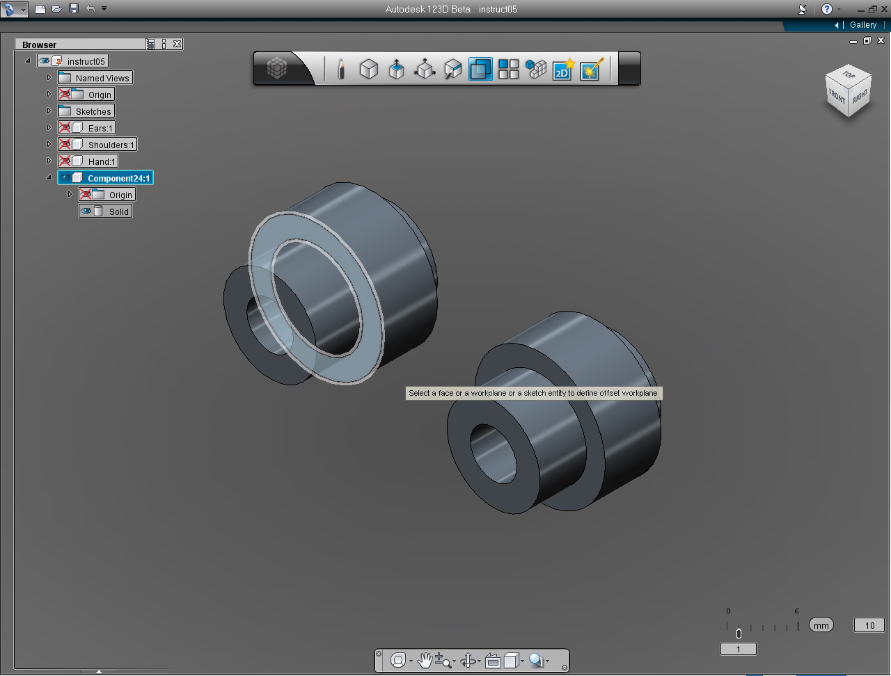
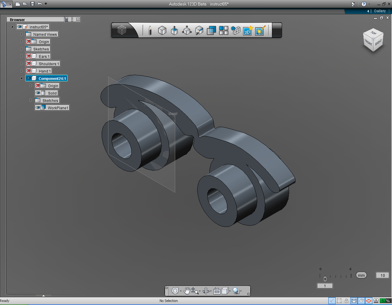
1. Select "Offset Plane" pill in "Construction" Marking Menu.
2. Move cursor over the bottom plane of the largest cylinder of the eye.
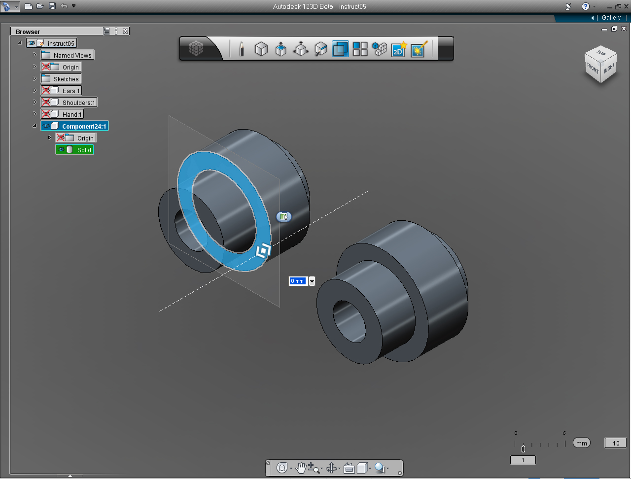
3. The bi-directional arrow shows up, just leave the value as the default, by make a right click.
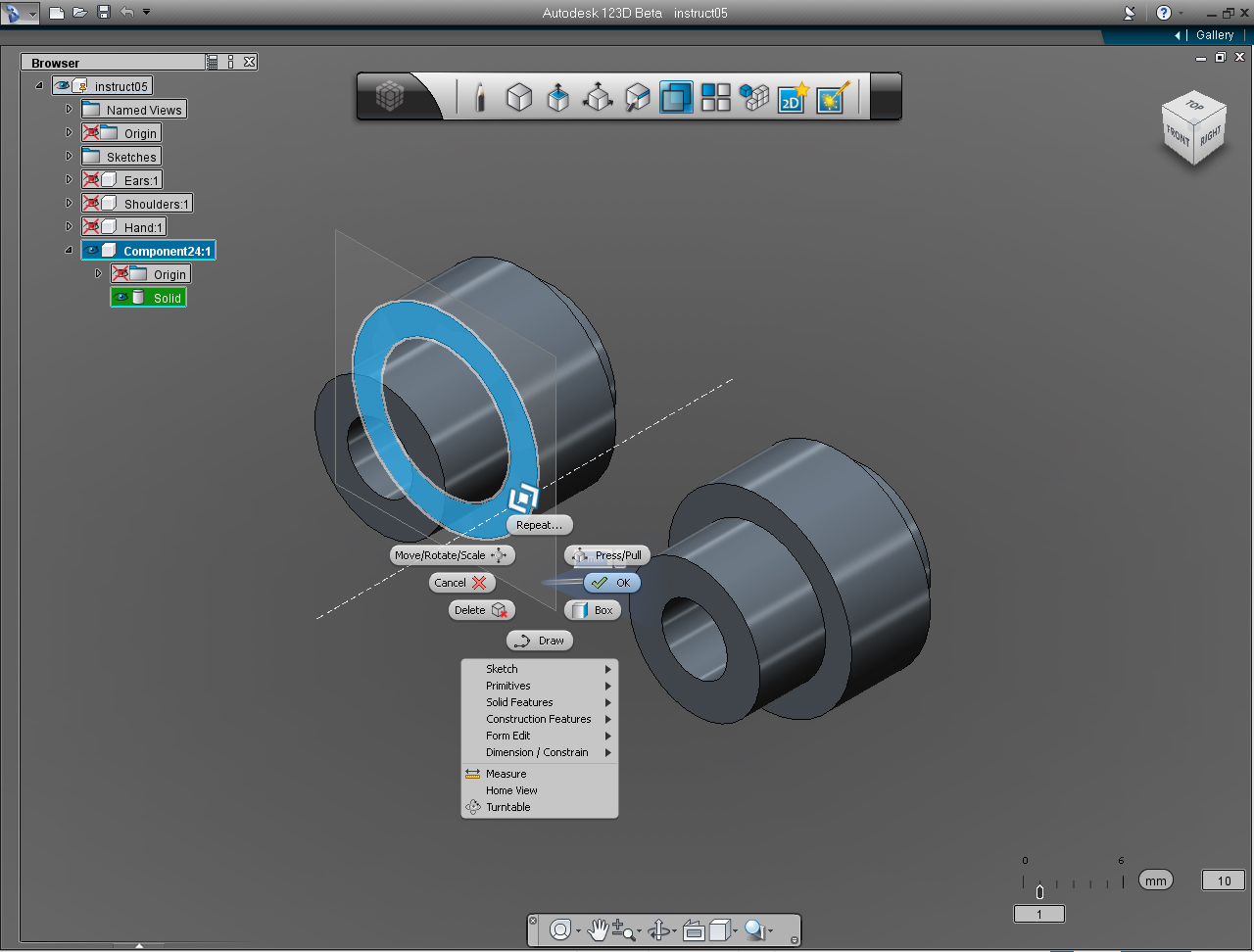
4. Select "OK" on the Marking Menu to commit the command.
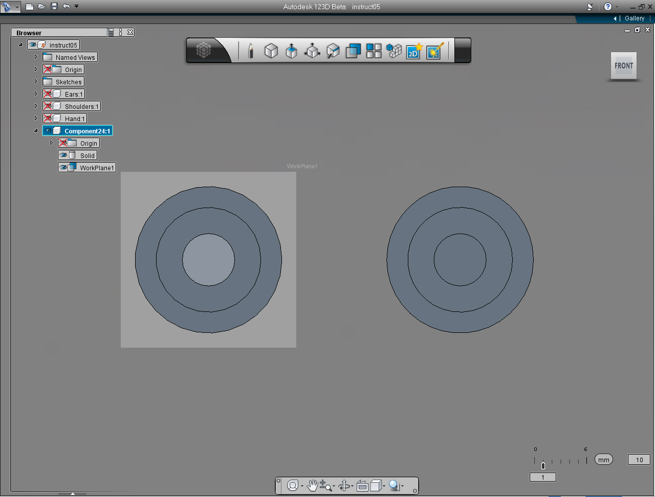
5. New "WorkPlane" item appeared on the "Feature Browser" list. Set the "View Cube" to be FRONT view.
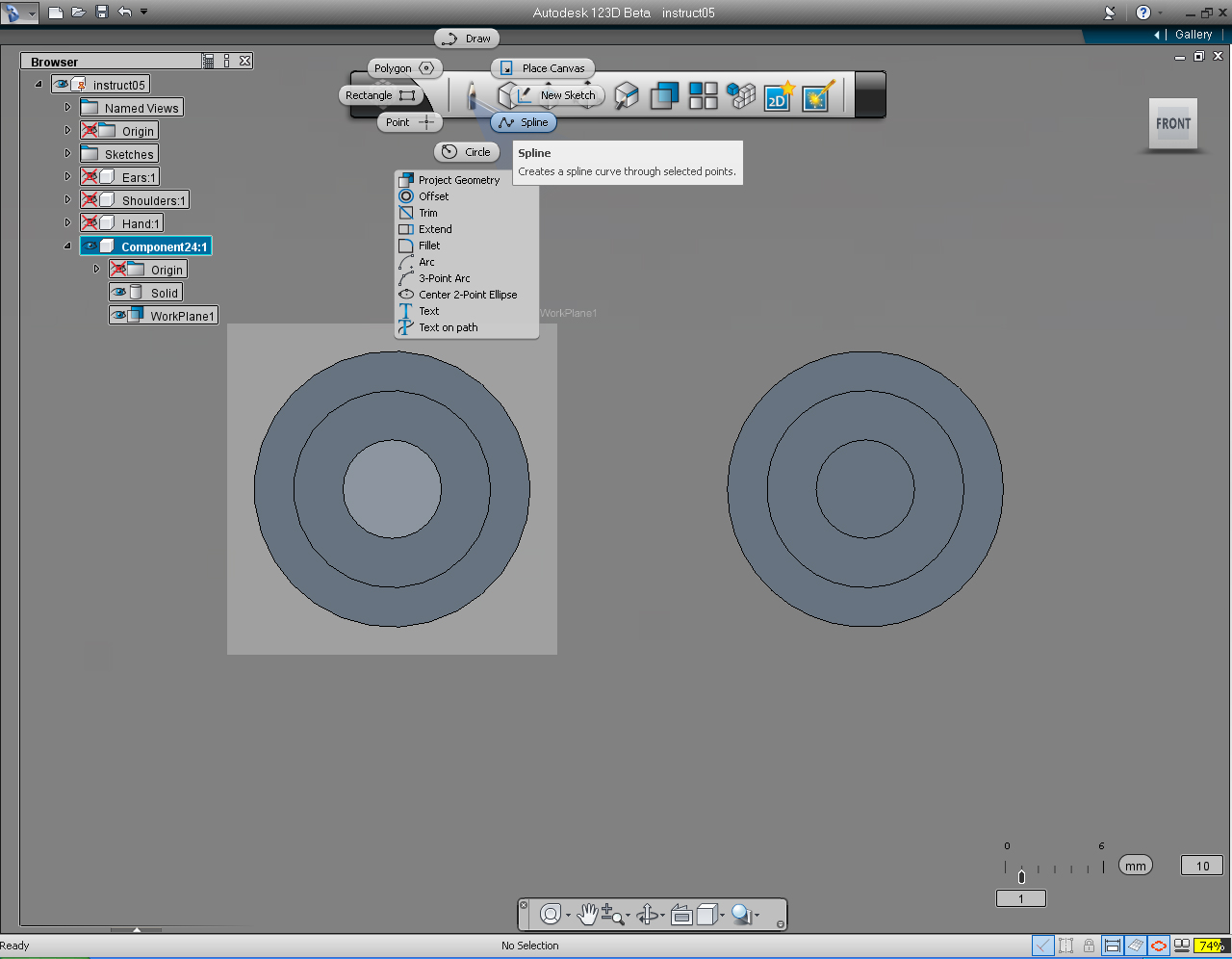
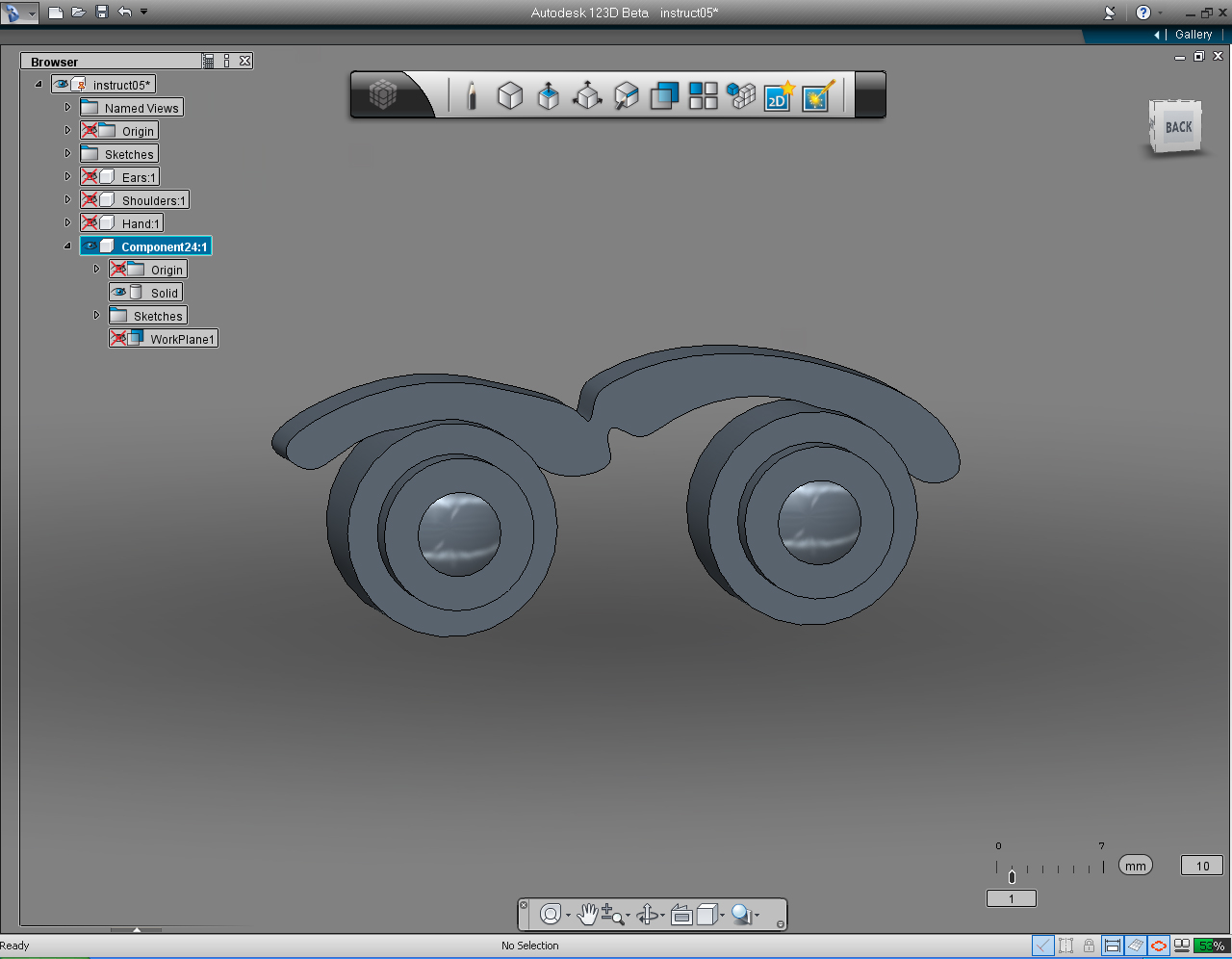
6. Select "Spline" pill from the "Sketch" Marking Menu.
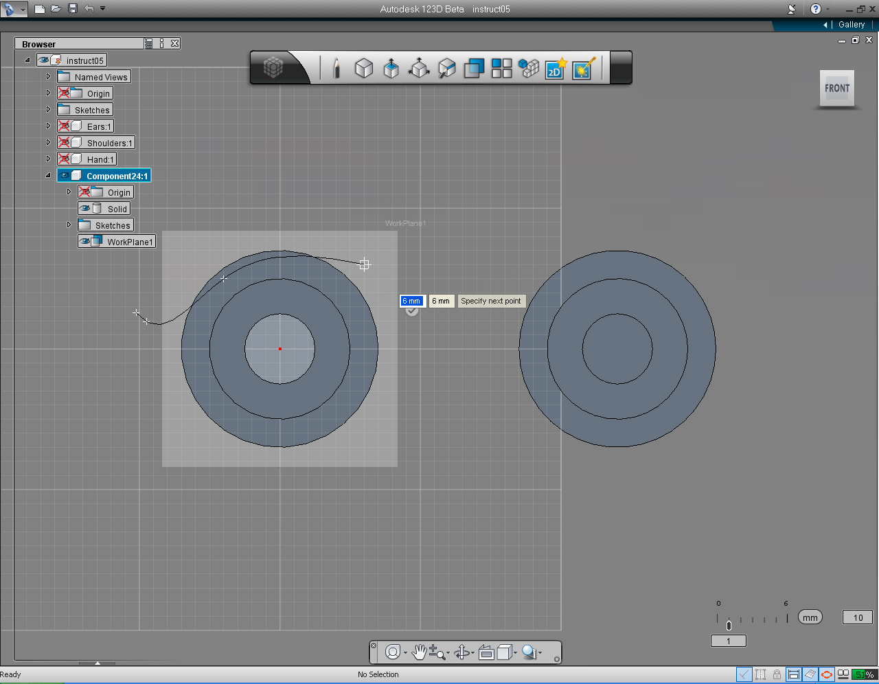
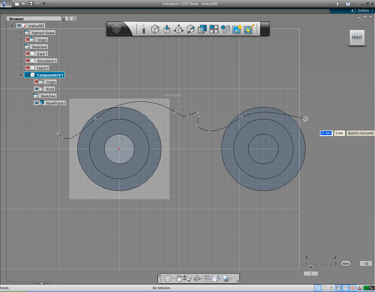
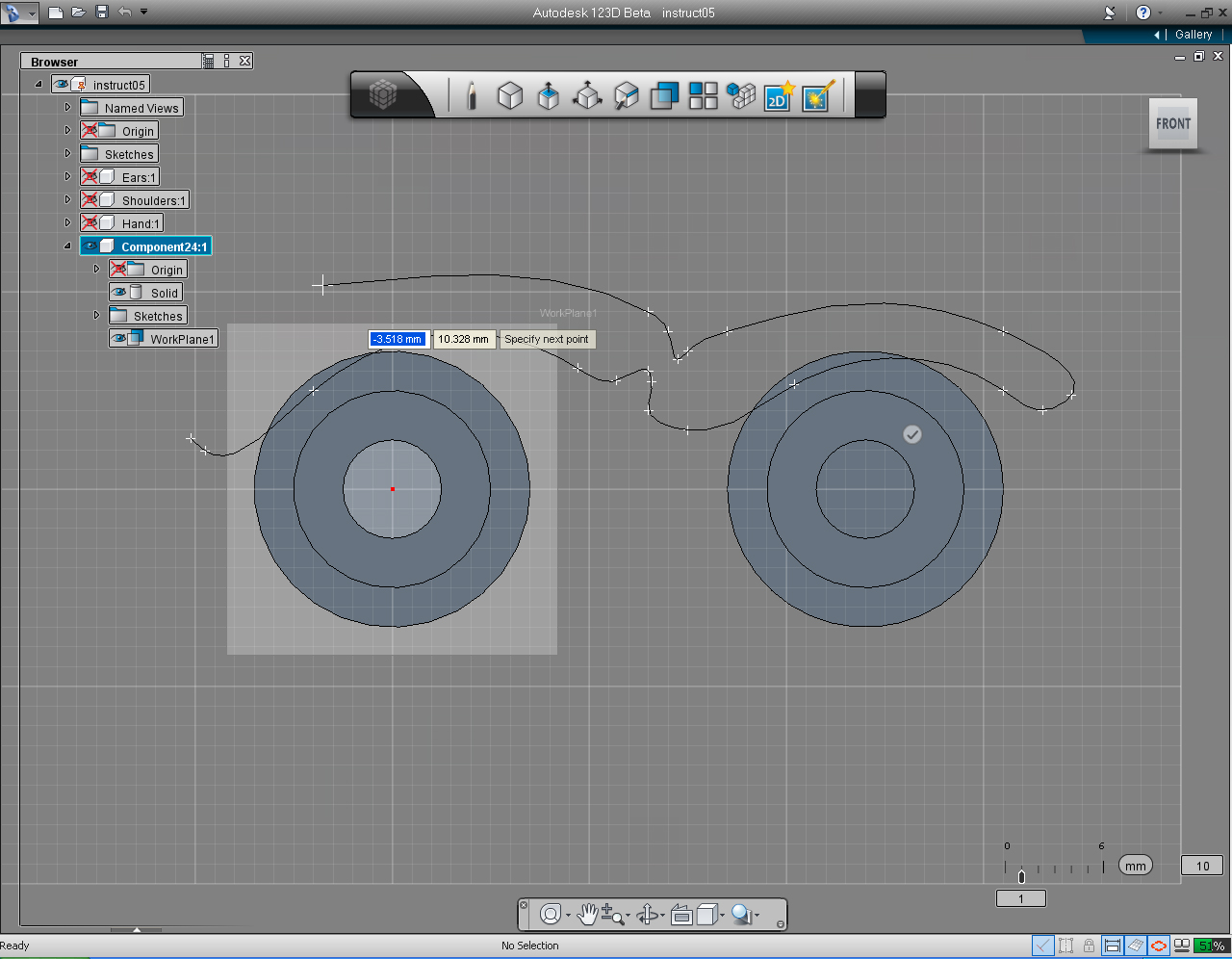
Note: In the next few steps, you are going to draw the spline. Just for fun! You could design your own eyebrows. So you do not have to specify the end point of the spline does not have to be exact as the sample. As well as the amount of points does not have to match exactly as shown in the sample image.
I leave this up to you. So be creative!
Or if you want to do as in the sample, you just use the endpoint position as shown in the images.
But you need to close the spline you draw, and the eyebrows must not be separated.
7 - 10. Plot end points to draw "Spline".
11. Rotate the "View Cube" to the "BACK" plane.
12. Pick any point on the spline and move the mouse to move the point around, you will see that the spline change it shape. Adjust the point to fit your need, otherwise press "Esc" key to cancel editing the spline.
13. Right click on the eyebrows, to bring up the Marking Menu. Then select "Extrude" pill.
14. Move "View Cube" into Home view.
15. Drag bi-directional arrow to specify the extrude length or keyboard input the value of -4mm.
16. Right click again to bring up the Marking Menu. Select "OK" pill to commit.
17. Well, the result was not as we expected! 123D just trimmed the eyebrows out of the eyes. What should we do?
18. That all right! All we need to do is select "Undo" function from the "Application" Menu. And everything will go back to the previous step we did.
19. Before redo the "Extrude" command. Hide the "Solid" model of the eyes.
20.. Right click on the eyebrows, to bring up the Marking Menu. Then select "Extrude" pill.
21. Drag bi-directional arrow to specify the extrude length or keyboard input the value of -4mm. And right click again to bring up the Marking Menu. Select "OK" pill to commit.
22. Unhide the eyes by uncheck at the Solid model.
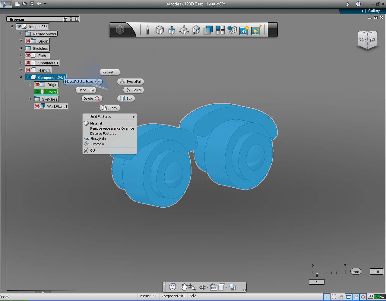
23. Use "Orbit" or "View Cube" to set the view as shown.
Next, we are going to rotate the model so the eyes point upward instead of the way it is.
24. Right click to bring up the Marking Menu.
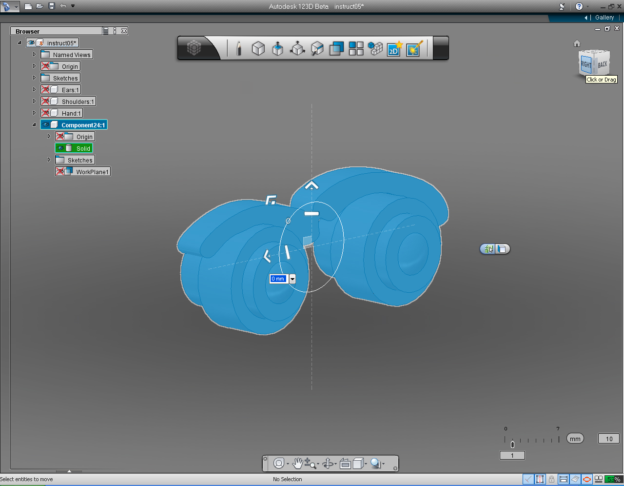
25. We can see that with this view, the "Move/Rotate/Scale" manipulator would not able to rotate the eyes into the direction we intend. So, set "View Cube" to RIGHT plane.
26. Use "Rotate" manipulator or keyboard input to rotate the model 90 deg.
27. Rename the "Component" to "Eyes"
Assemble 3D Models: Part 1 - Move Parts
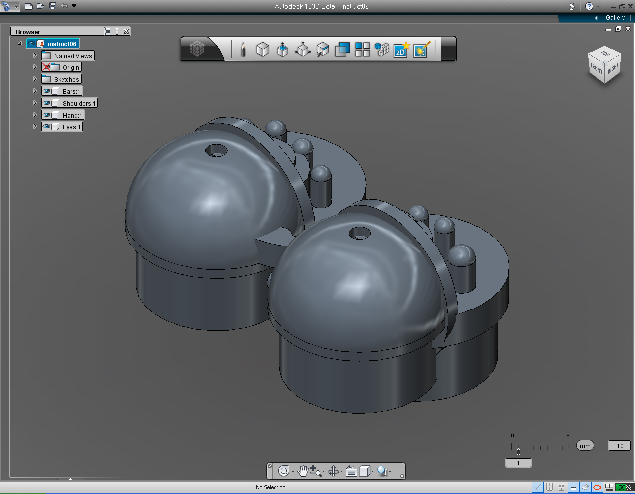
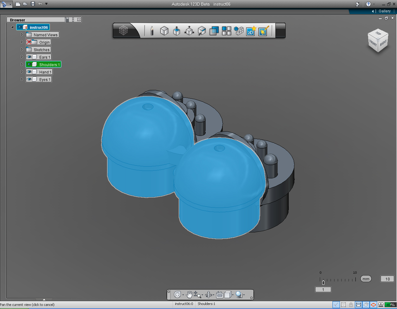
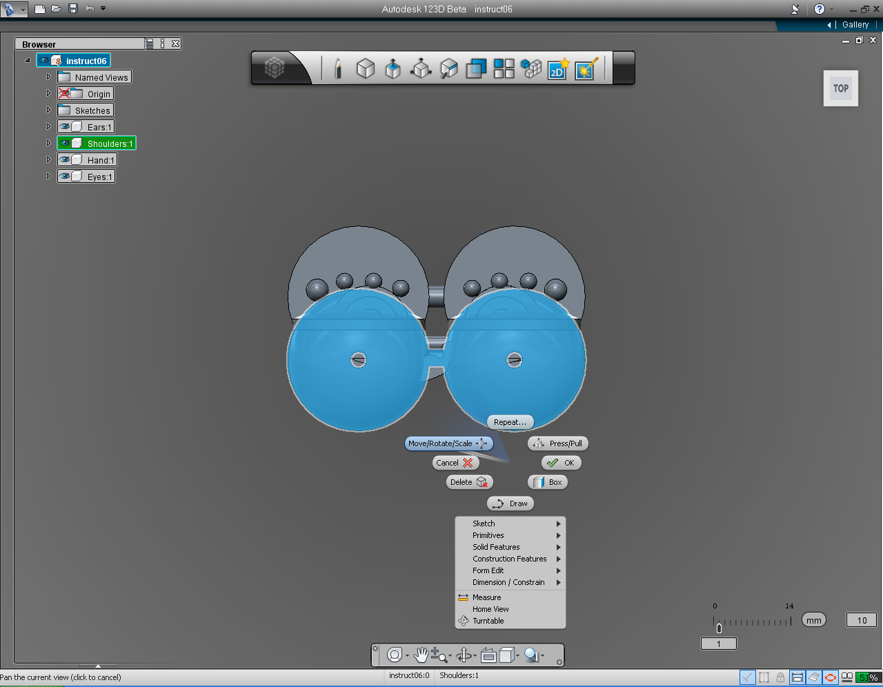
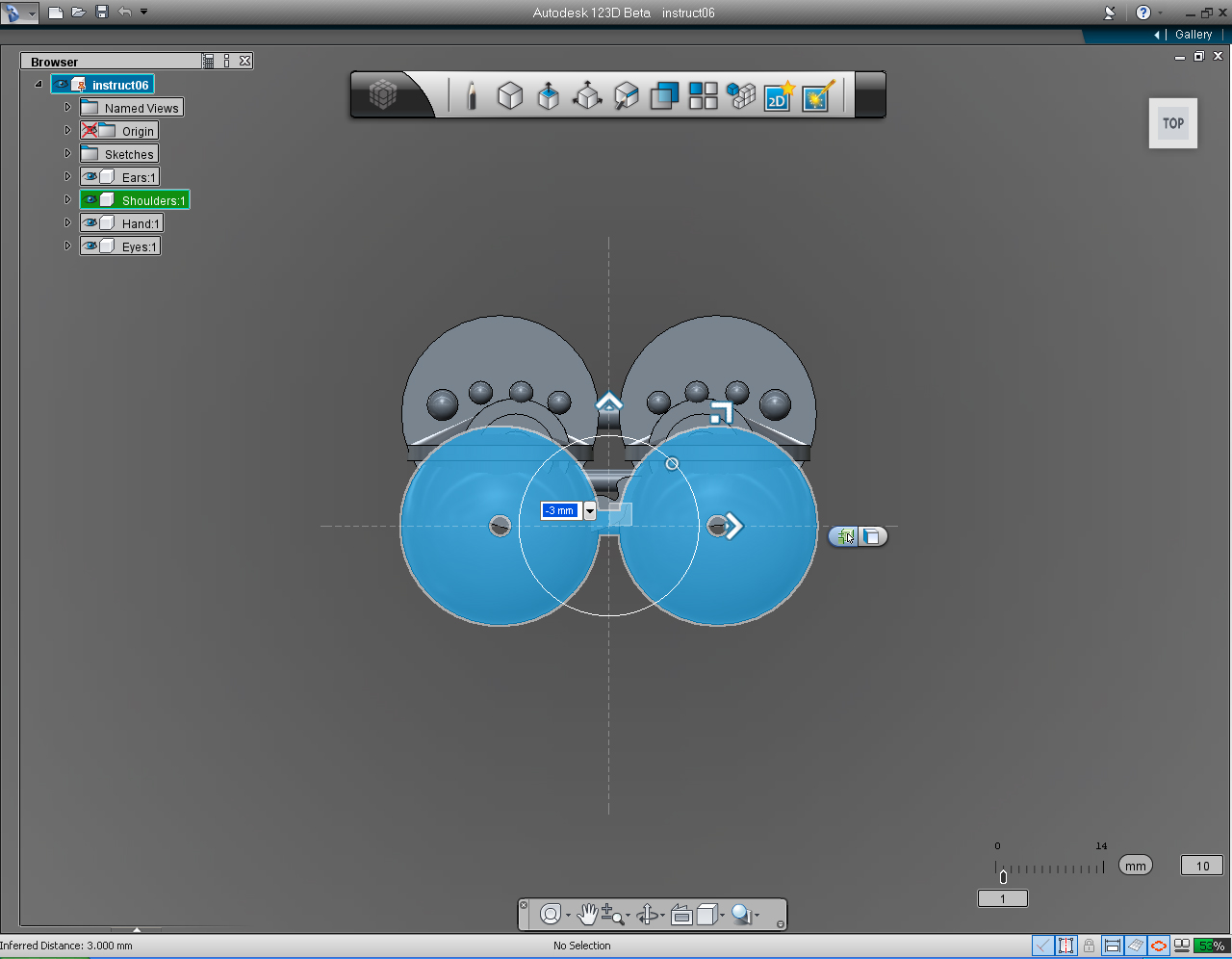
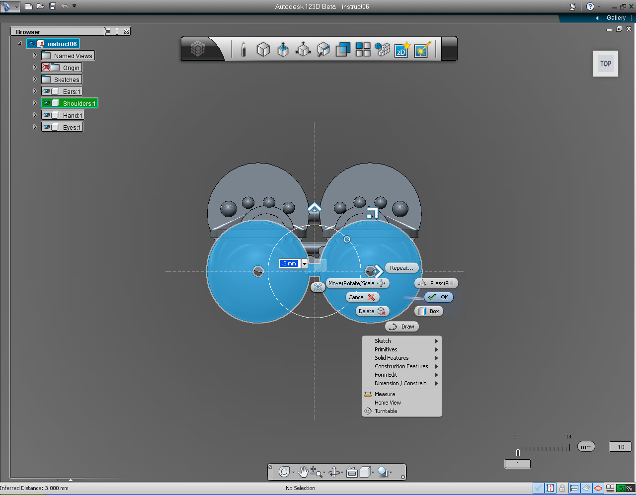
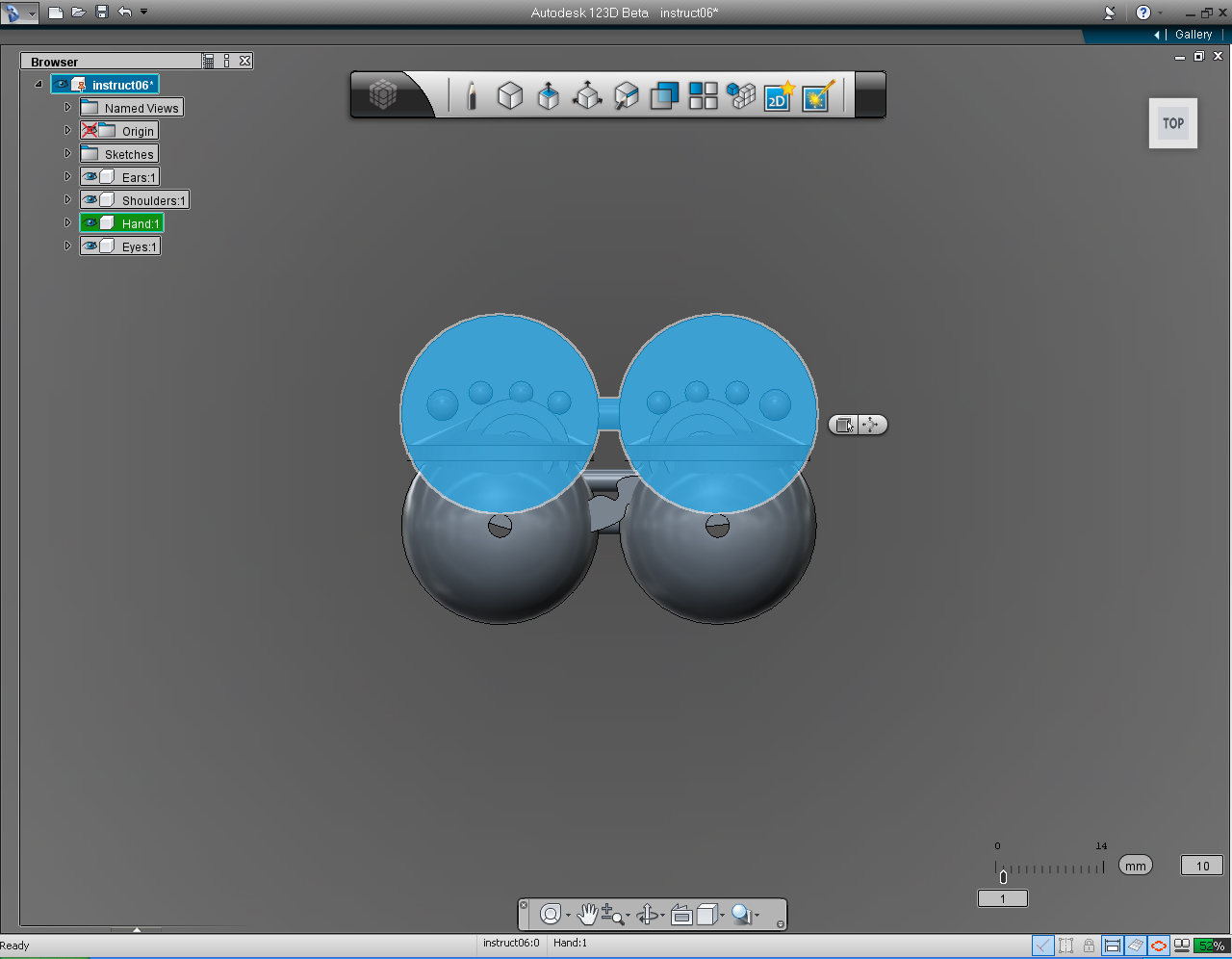
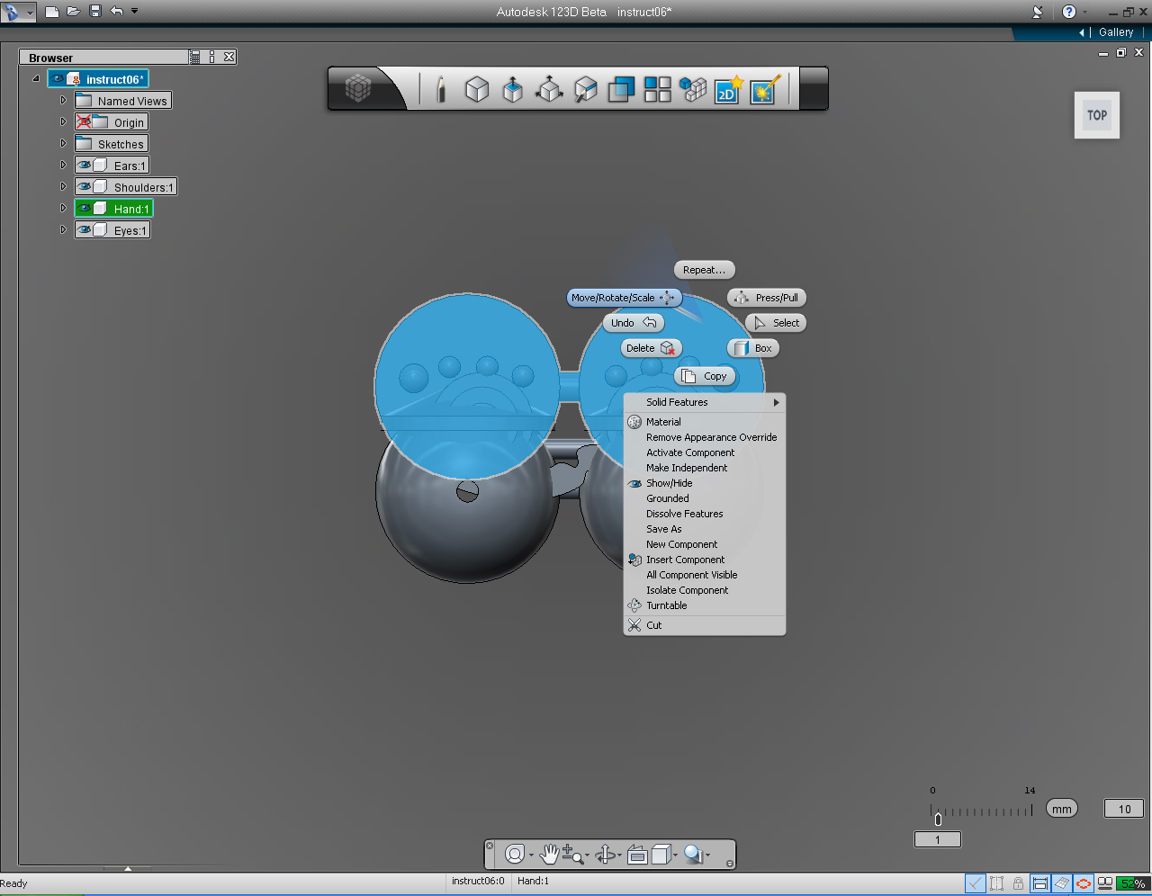
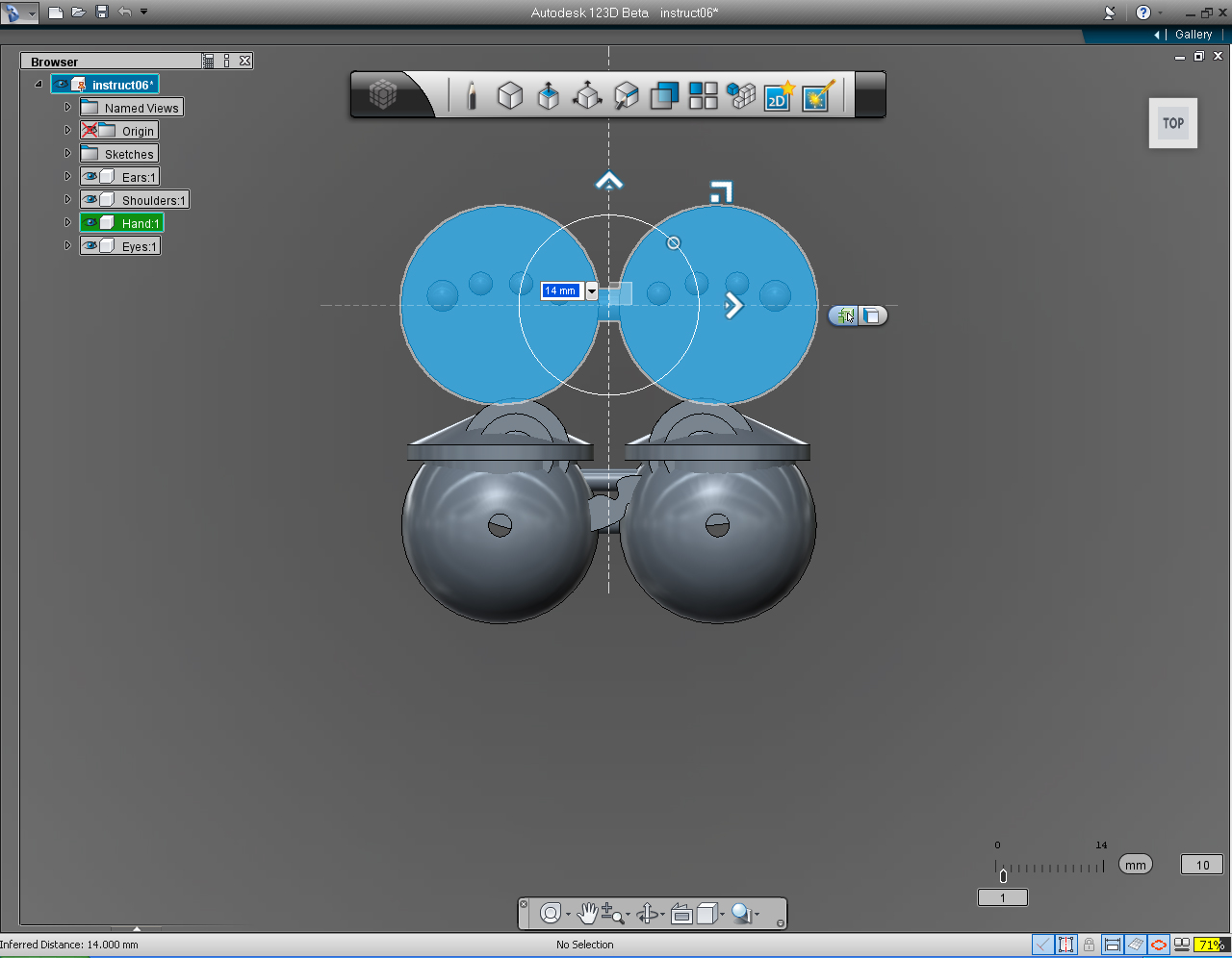
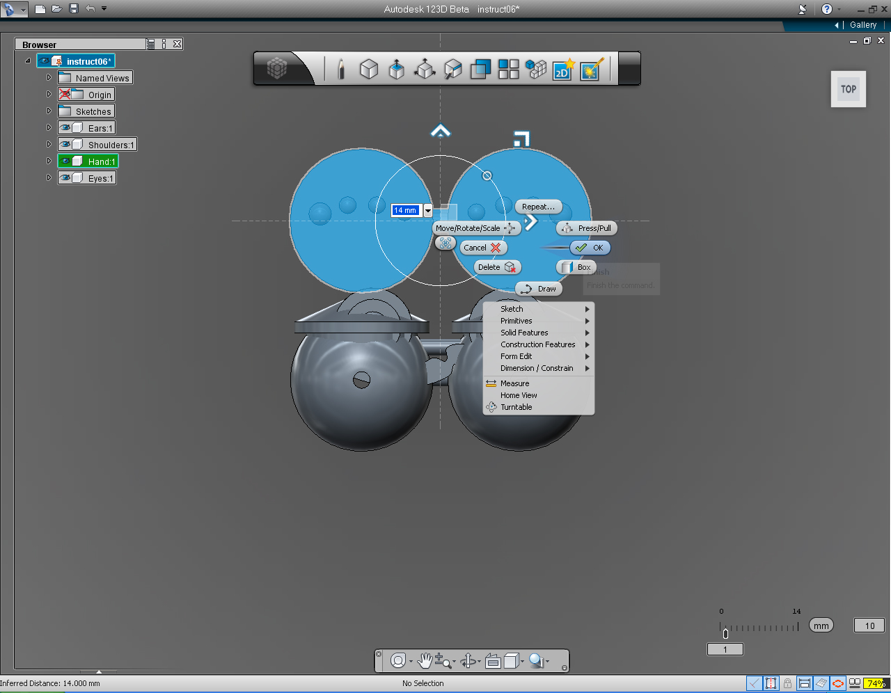
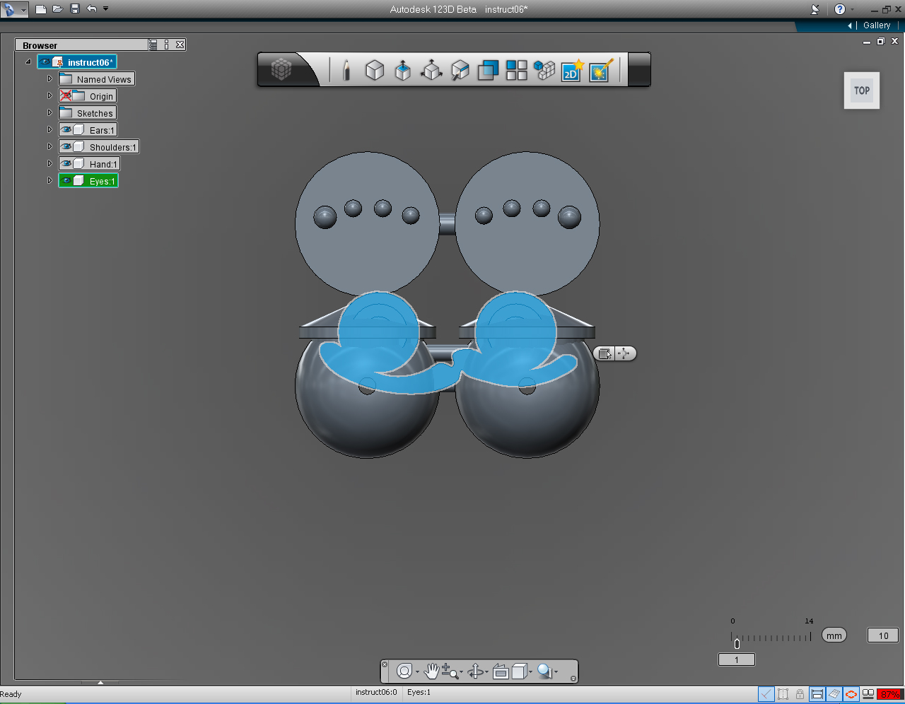
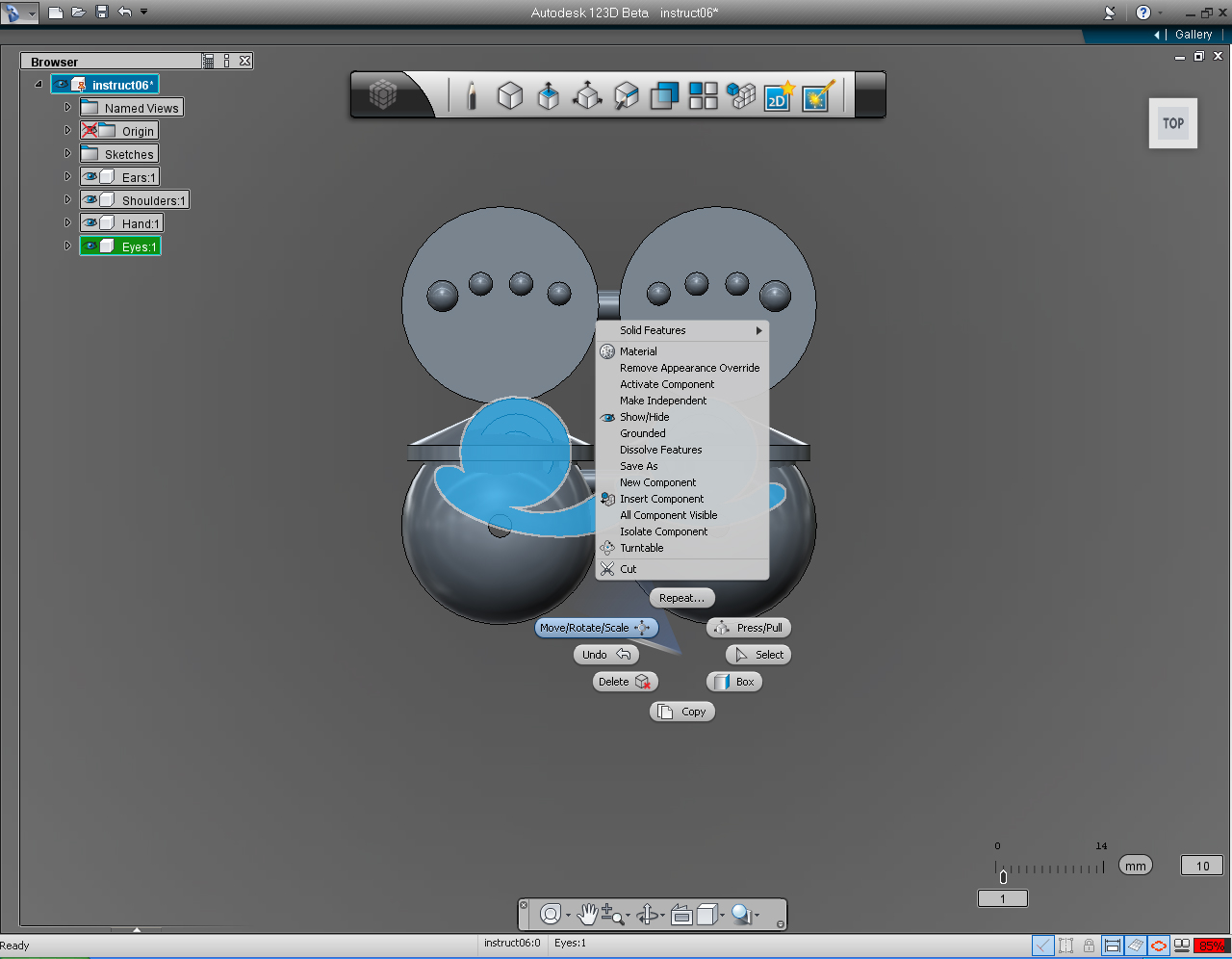
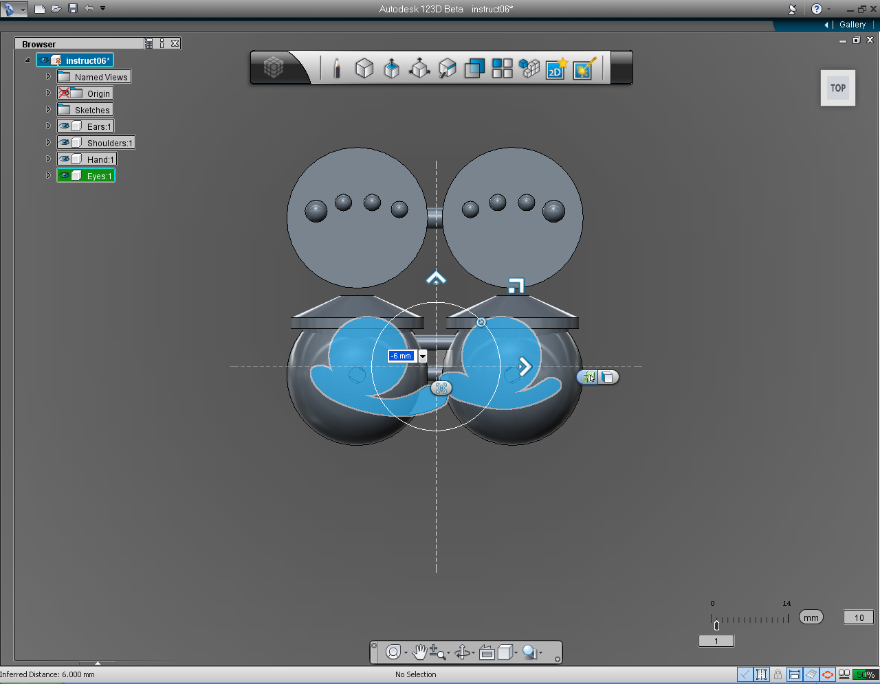
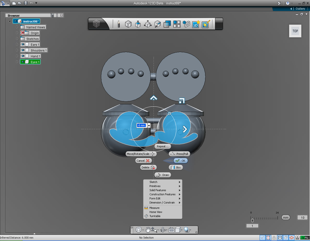
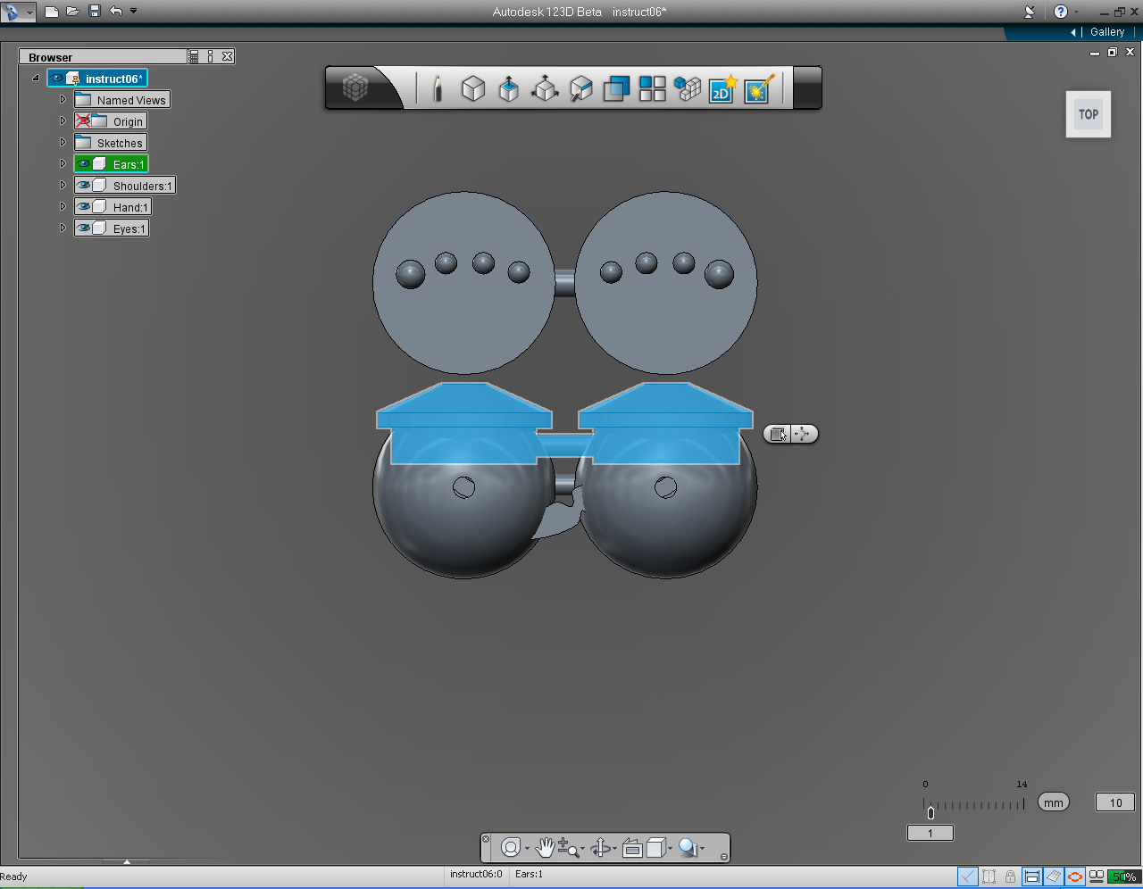
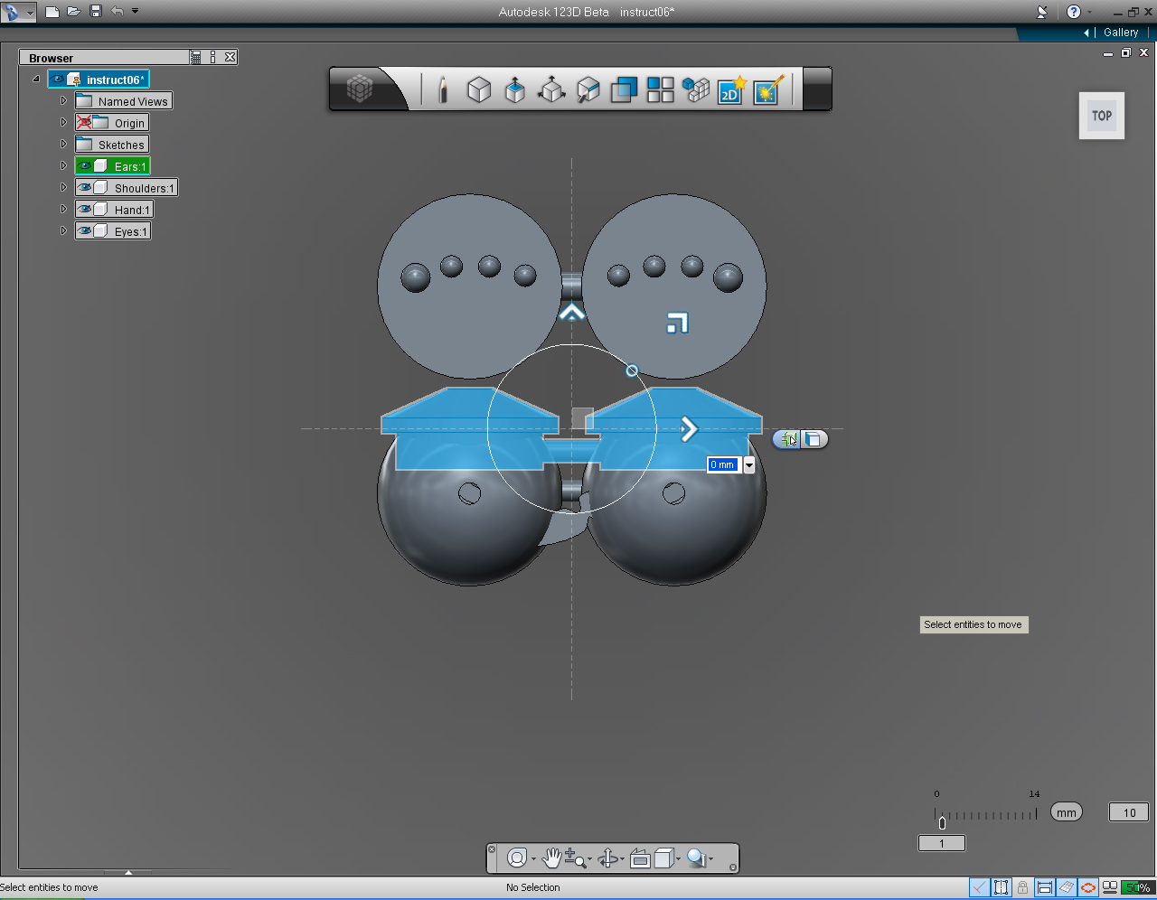
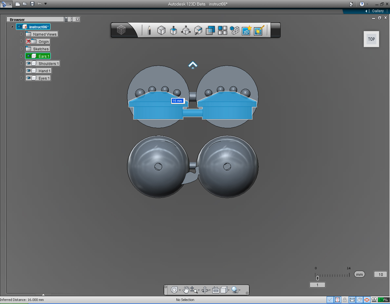
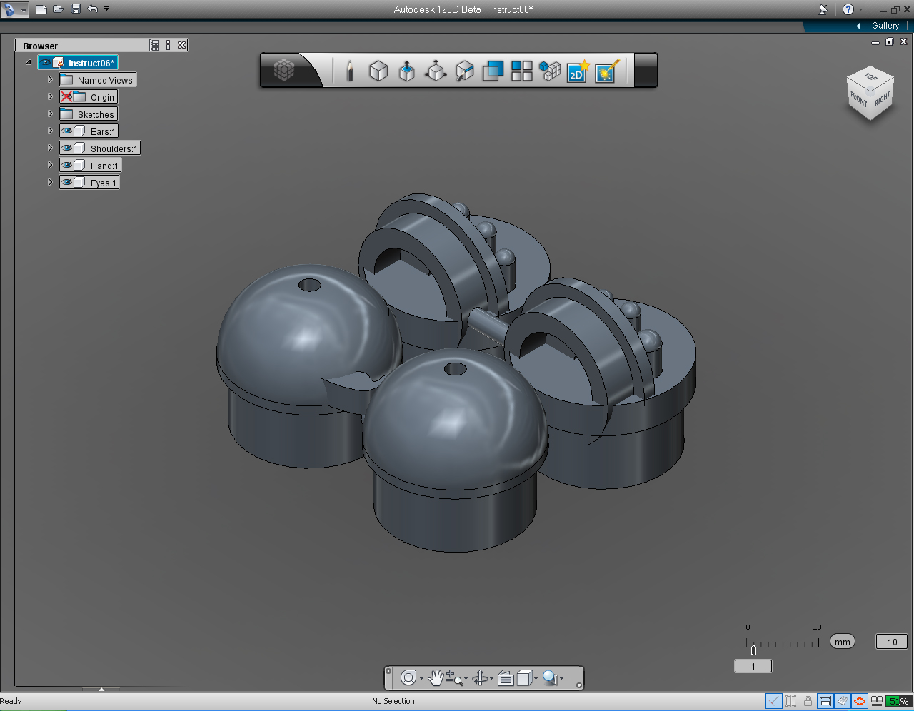
In this exercise, we are going to do a lot of
- "Move" to align objects, and
- "Rotate" while switching between
- "View", using the interactive "View Cube".
And we are going to
- Move and rotate shoulders
- Move, and Rotate hands
- Move, and Rotate eyes
- Move, and Rotate ears
Here are the steps:
1. Unhide all the solid models.
2. Select "Shoulder" Solid Model.
3. Change "View Cube" to TOP view.
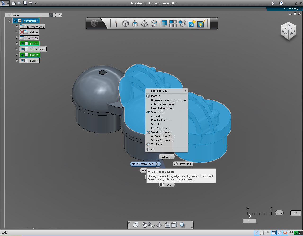
4. Right click to bring up Marking Menu. And Select "Move/Rotate/Scale" pill.
5. Drag the up arrow toward the bottom of screen or keyboard input the value to -3mm.
6. Right click mouse button, then click at "OK" pill to commit the command.
7. Select the "Hands" solid model.
8. Right click to bring up Marking Menu. And Select "Move/Rotate/Scale" pill.
9. Drag the up arrow toward the top of screen or keyboard input the value to 14mm.
10. Right click mouse button, then click at "OK" pill to commit the command.
11. Select the "Eyes" solid model.
12. Right click to bring up Marking Menu. And Select "Move/Rotate/Scale" pill.
13. Drag the up arrow toward bottom of screen or keyboard input the value to -6mm.
14. Right click mouse button, then click at "OK" pill to commit the command.
15. Select the "Ears" solid model.
16. Right click to bring up Marking Menu. And Select "Move/Rotate/Scale" pill.
17. Drag the up arrow toward top of screen or keyboard input the value to 16mm. And right click mouse button, then click at "OK" pill to commit the command.
18. Rotate the "View Cube" to TOP view.
Assemble 3D Models: Part 2 - Move Parts Cont.
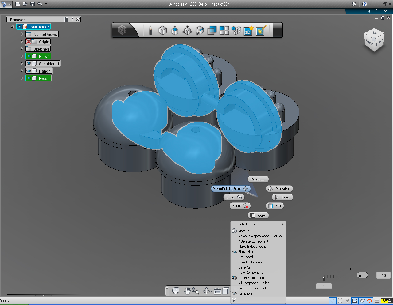
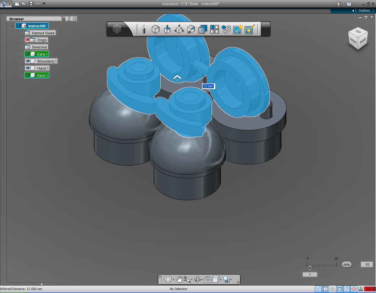
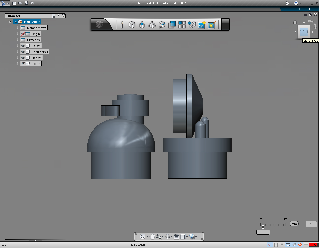
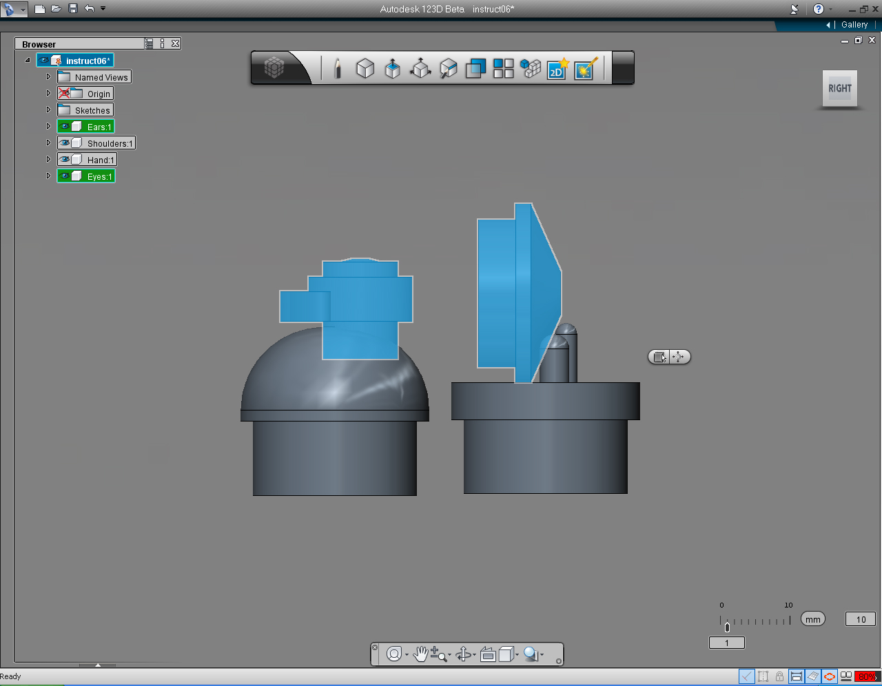
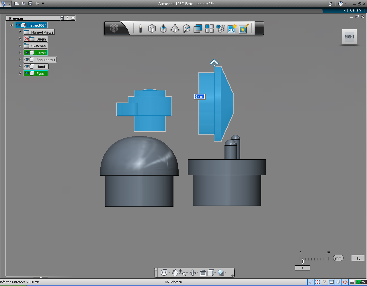
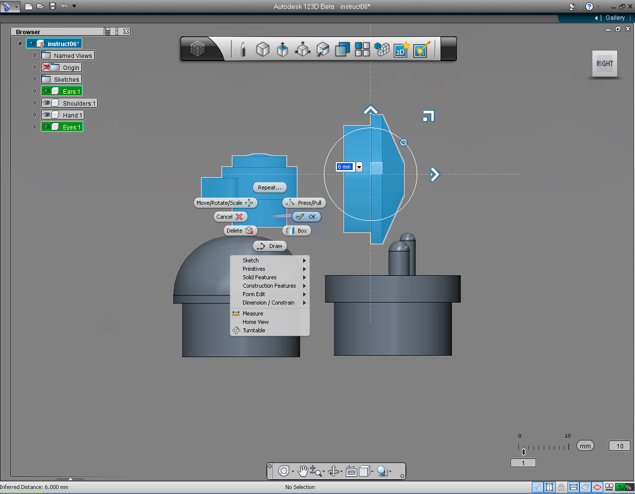
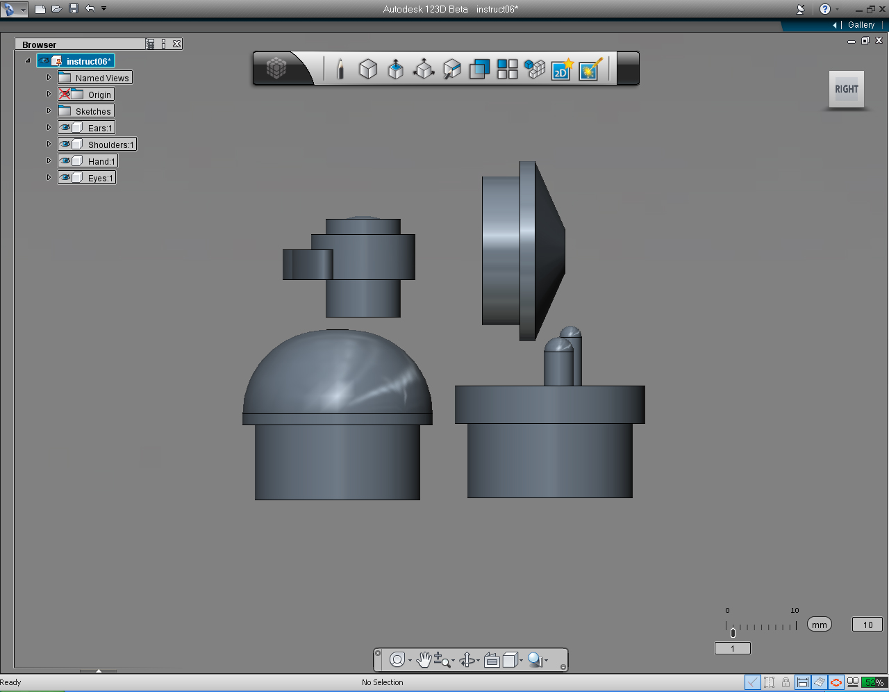
And we are going to
- Move and rotate shoulders
- Move, and Rotate hands
- Move, and Rotate eyes
- Move, and Rotate ears
Here are the steps:
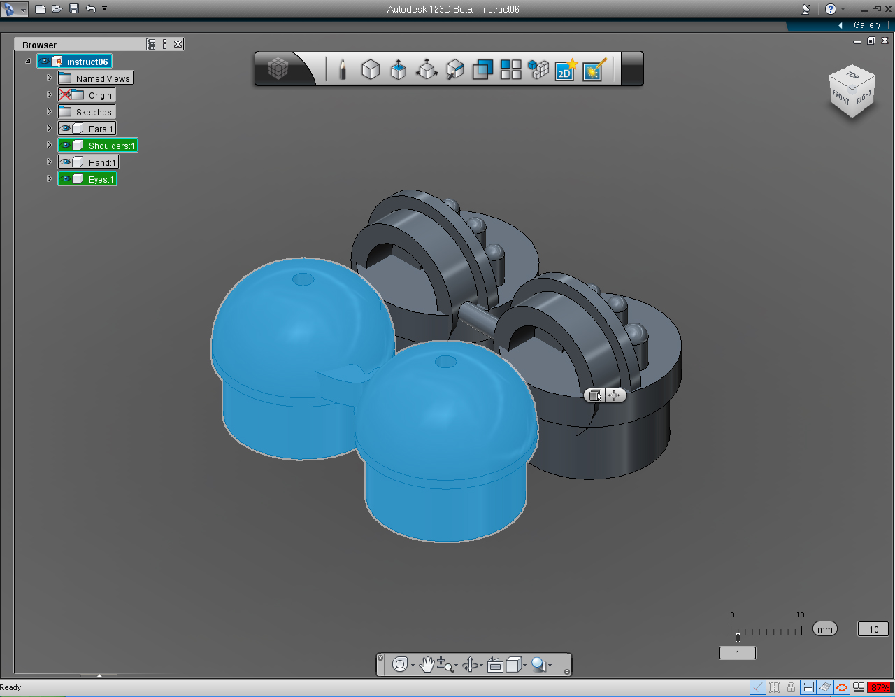
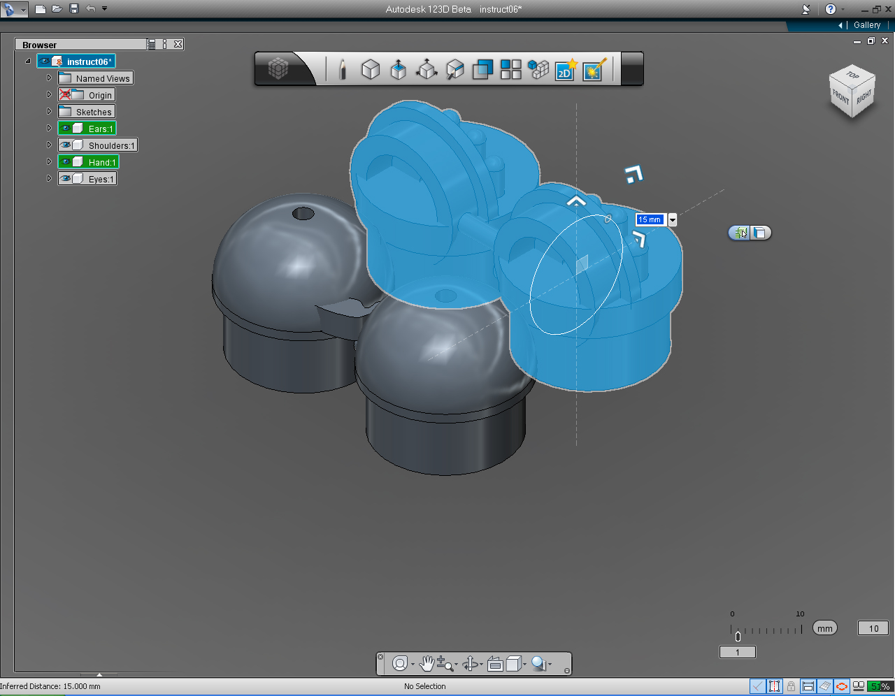
1. Select both "Shoulders" and "Eyes" Solid Models.
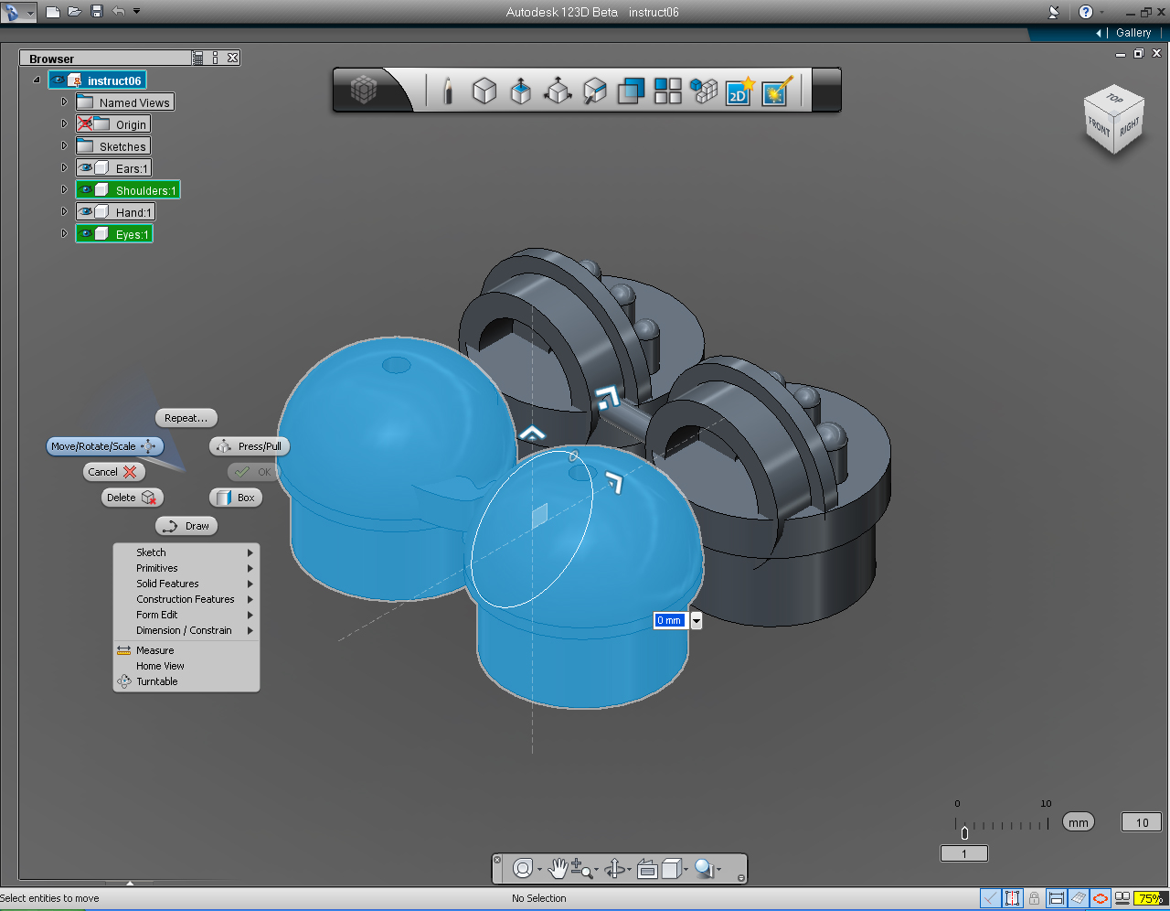
2. Right click to bring up Marking Menu. And Select "Move/Rotate/Scale" pill.
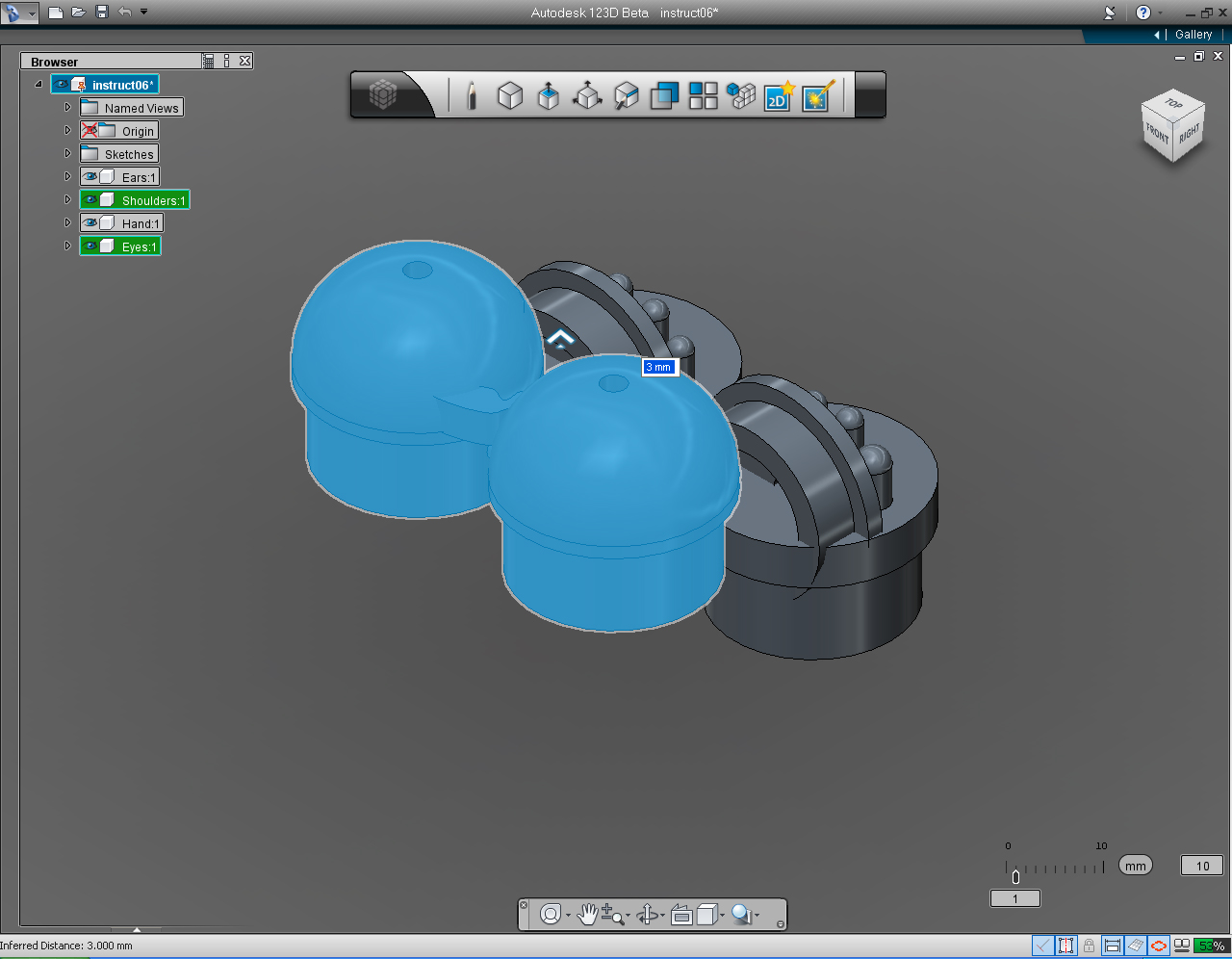
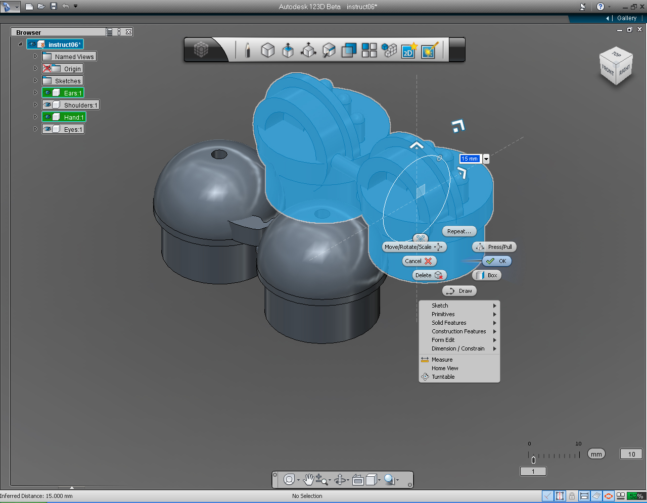
3. Drag the up arrow toward top of screen or keyboard input the value to 3mm. Then right click mouse button, then click at "OK" pill to commit the command.
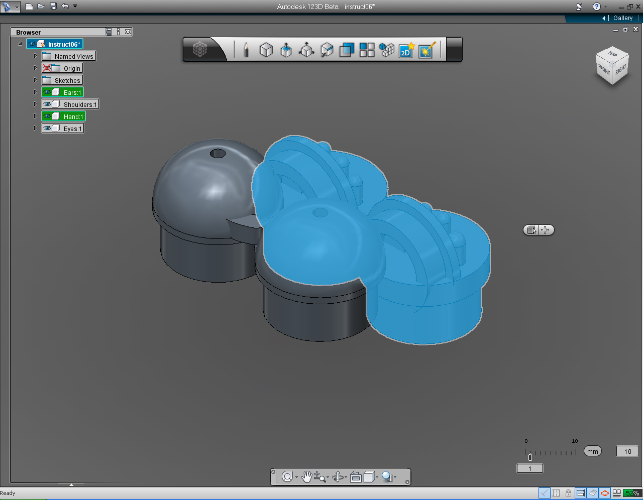
4. Now, select both "Hands" and "Ears" Solid Models.
5. Right click to bring up Marking Menu. And Select "Move/Rotate/Scale" pill.
6. Drag the up arrow toward the top of screen or keyboard input the value to 15mm.
7. Right click mouse button, then click at "OK" pill to commit the command.
8. Now, select both "Eyes" and "Ears" Solid Models.
9. Right click to bring up Marking Menu. And Select "Move/Rotate/Scale" pill.
10. Drag the up arrow toward the top of screen or keyboard input the value to 12mm. And right click mouse button, then click at "OK" pill to commit the command.
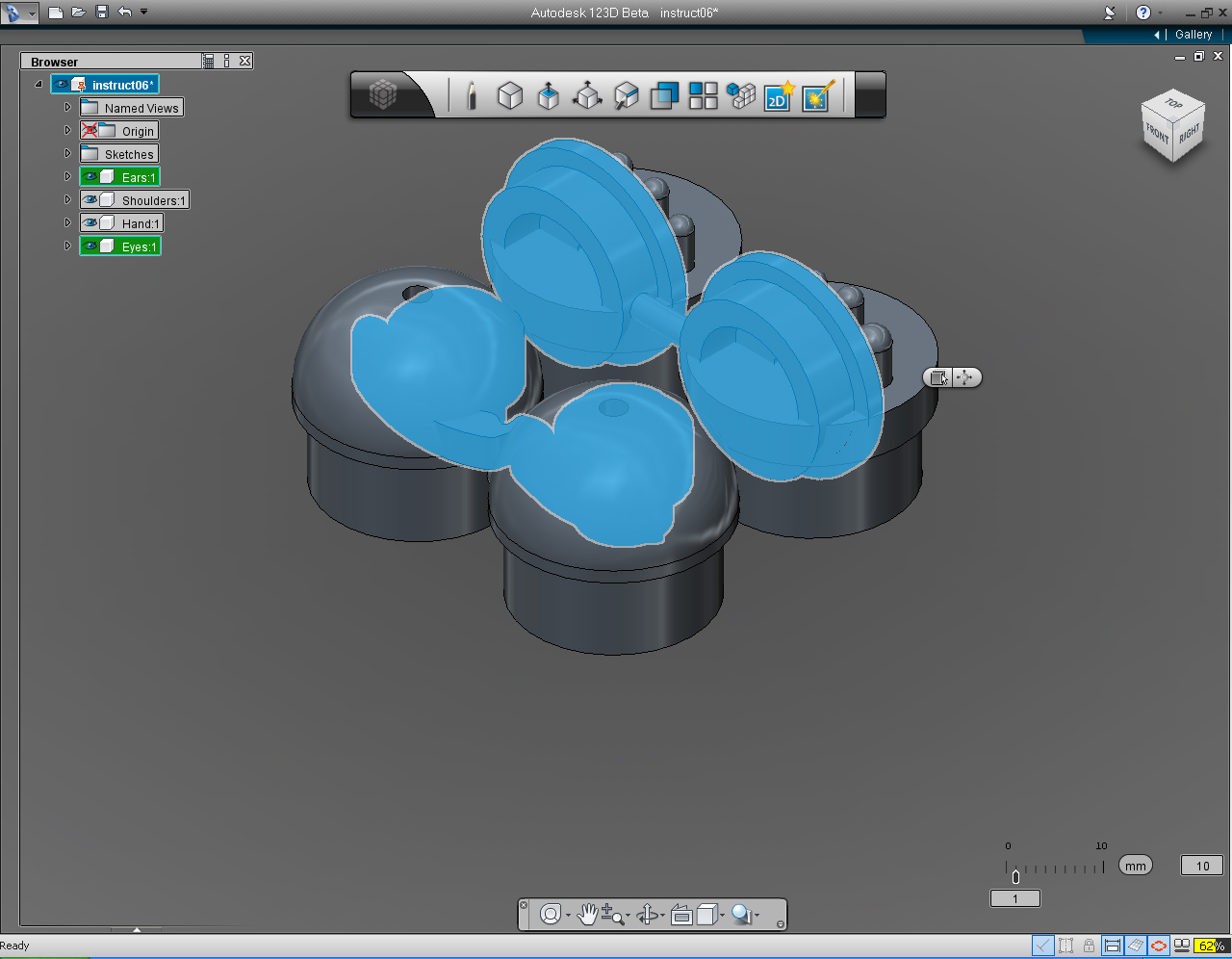
11. Set "View Cube" to RIGHT View.
12. Select both "Hands" and "Ears" Solid Models again.
13. Drag the up arrow toward the top of screen or keyboard input the value to 6mm.
14. And right click mouse button, then click at "OK" pill to commit the command.
All the models are seem to be in the perfect place now!
Assemble 3D Models: Part 2 - Combine Shoulders and Eyes
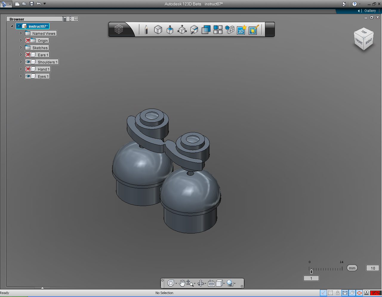
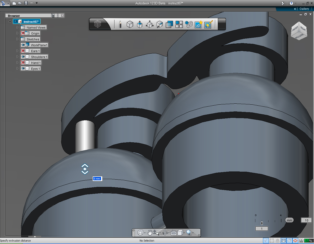
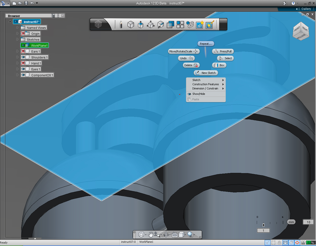
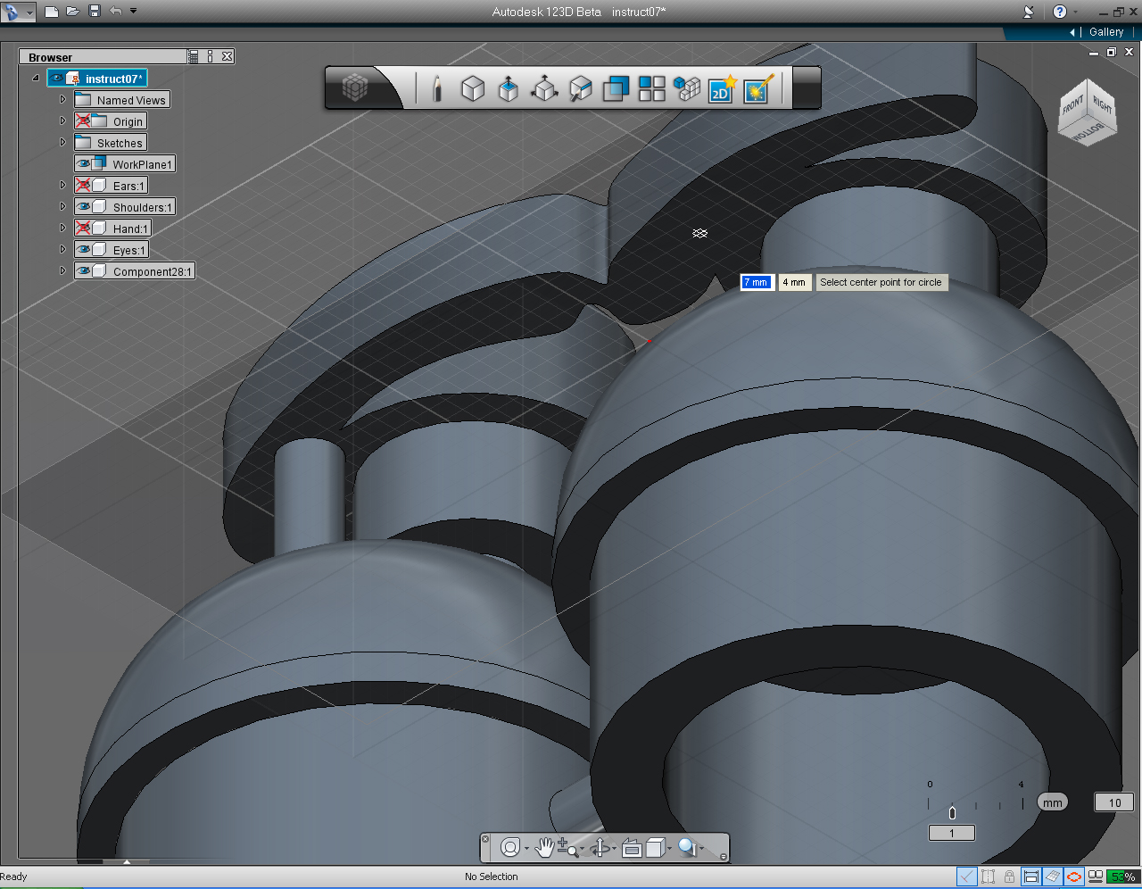
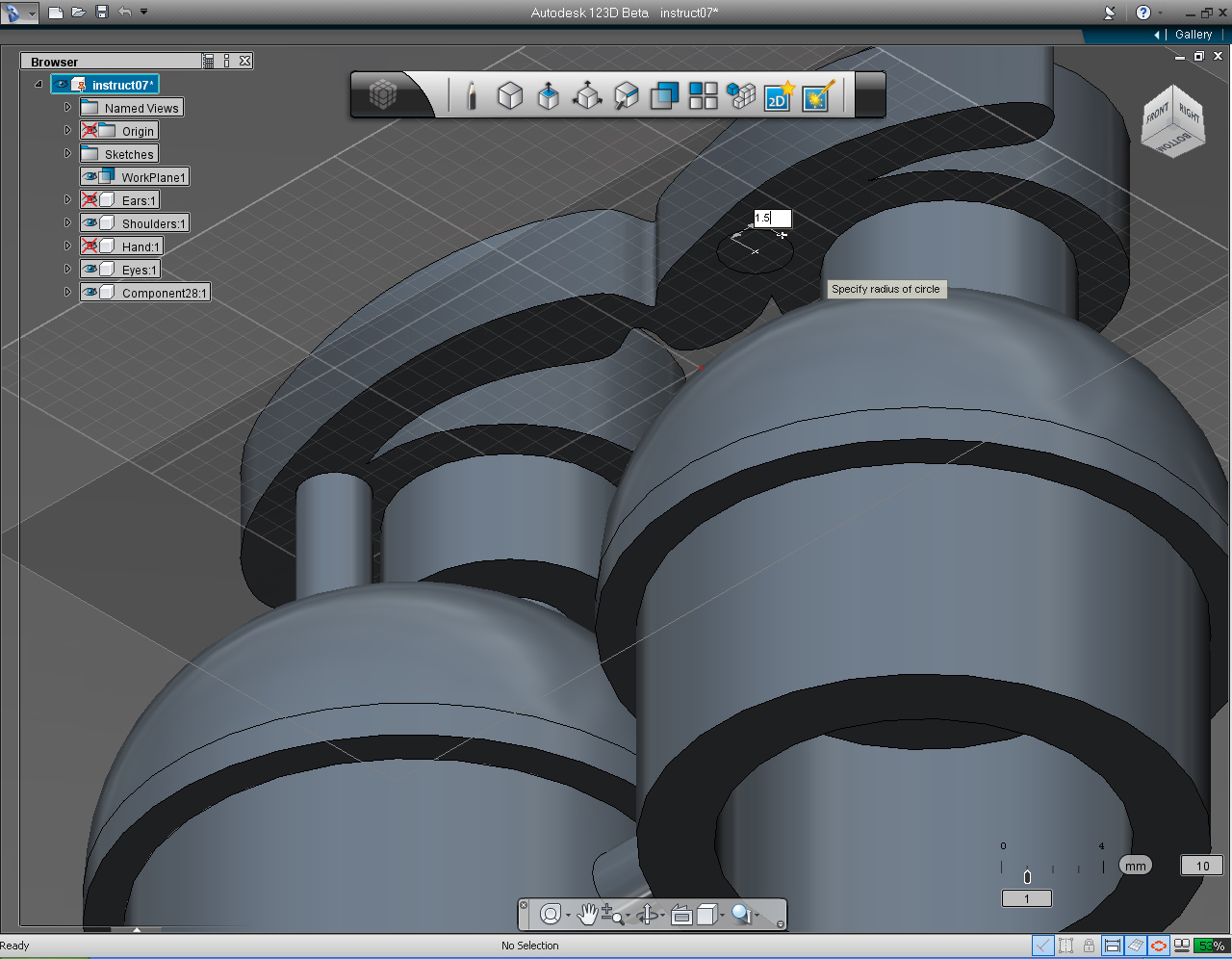
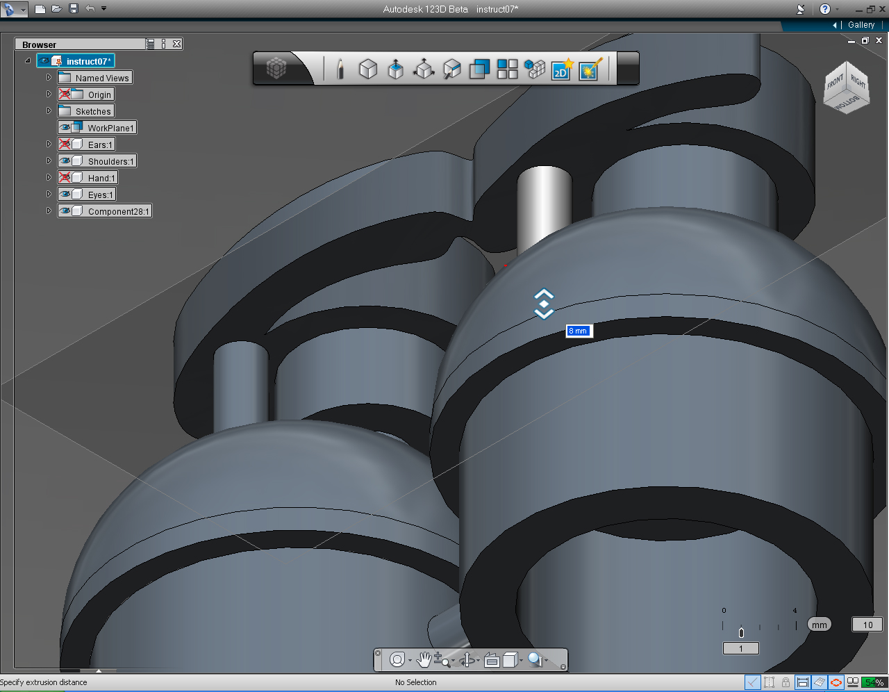
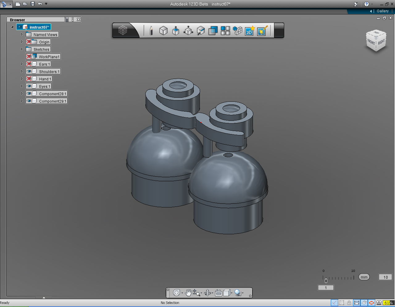
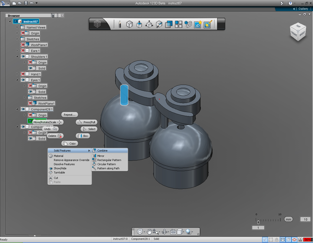
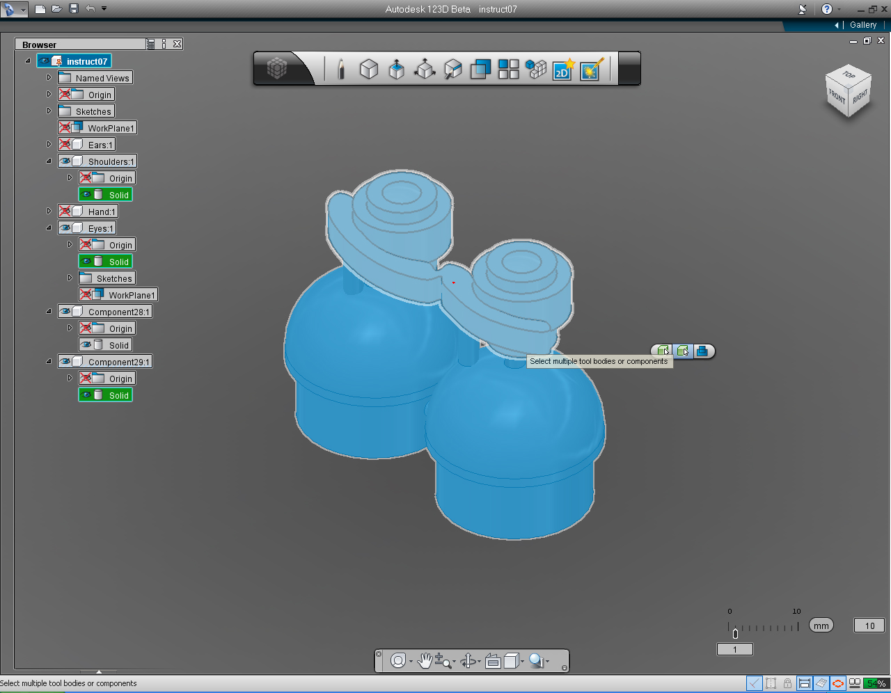
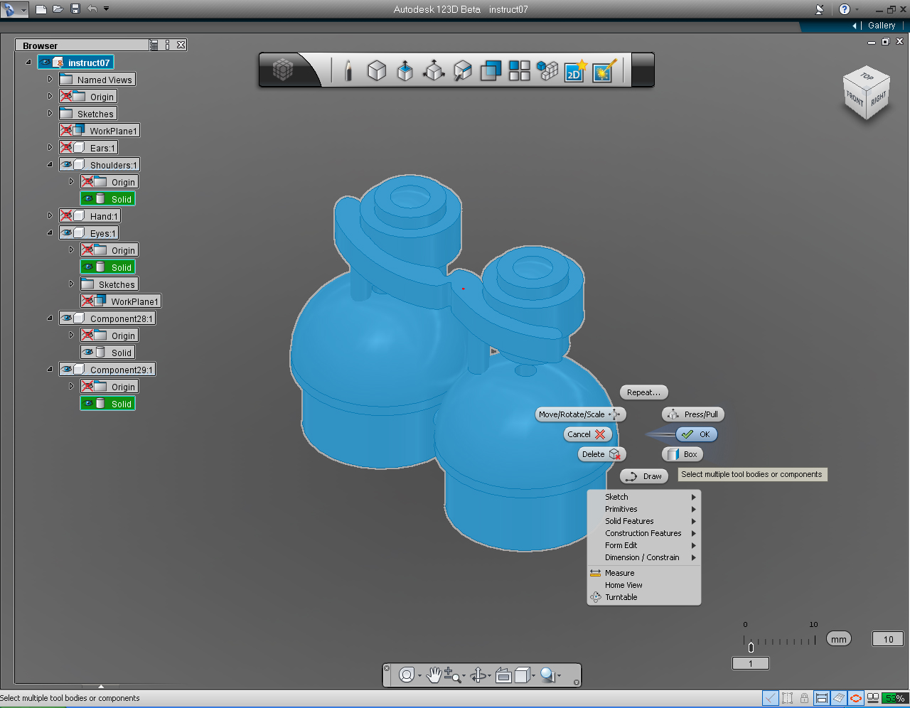
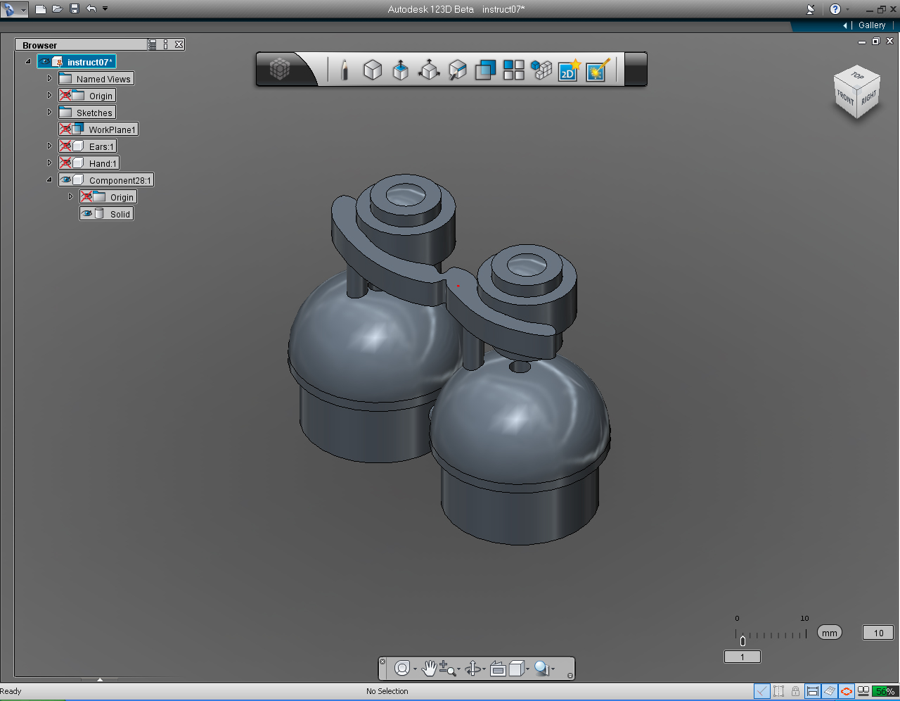
Summary of the commands to use in this step:
- "Offset Plane" in "Construction" Marking Menu
- "Cylinder" in the "Primitive" Marking Menu or bucket.
- "Combine" function in the "Create" Marking Menu
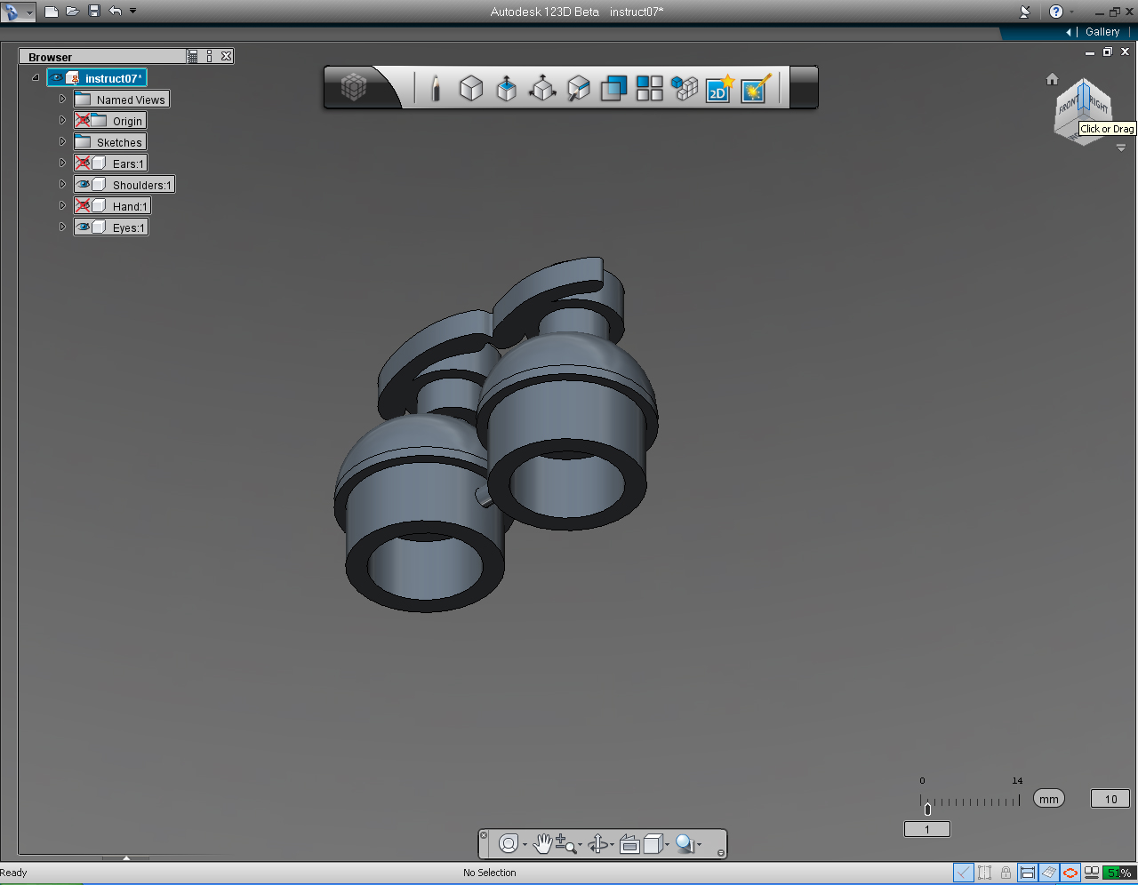
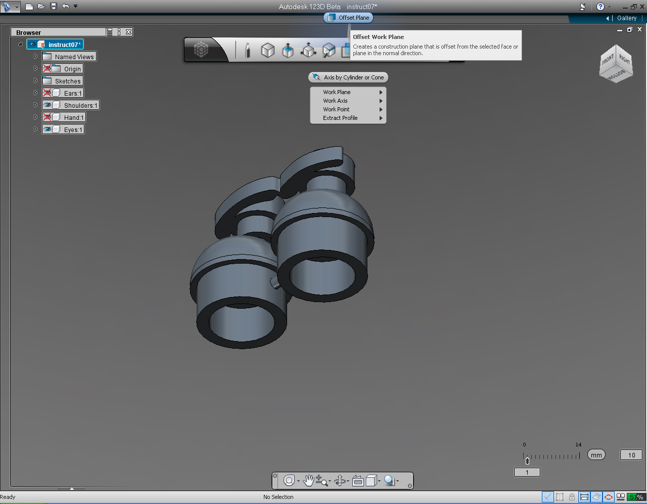
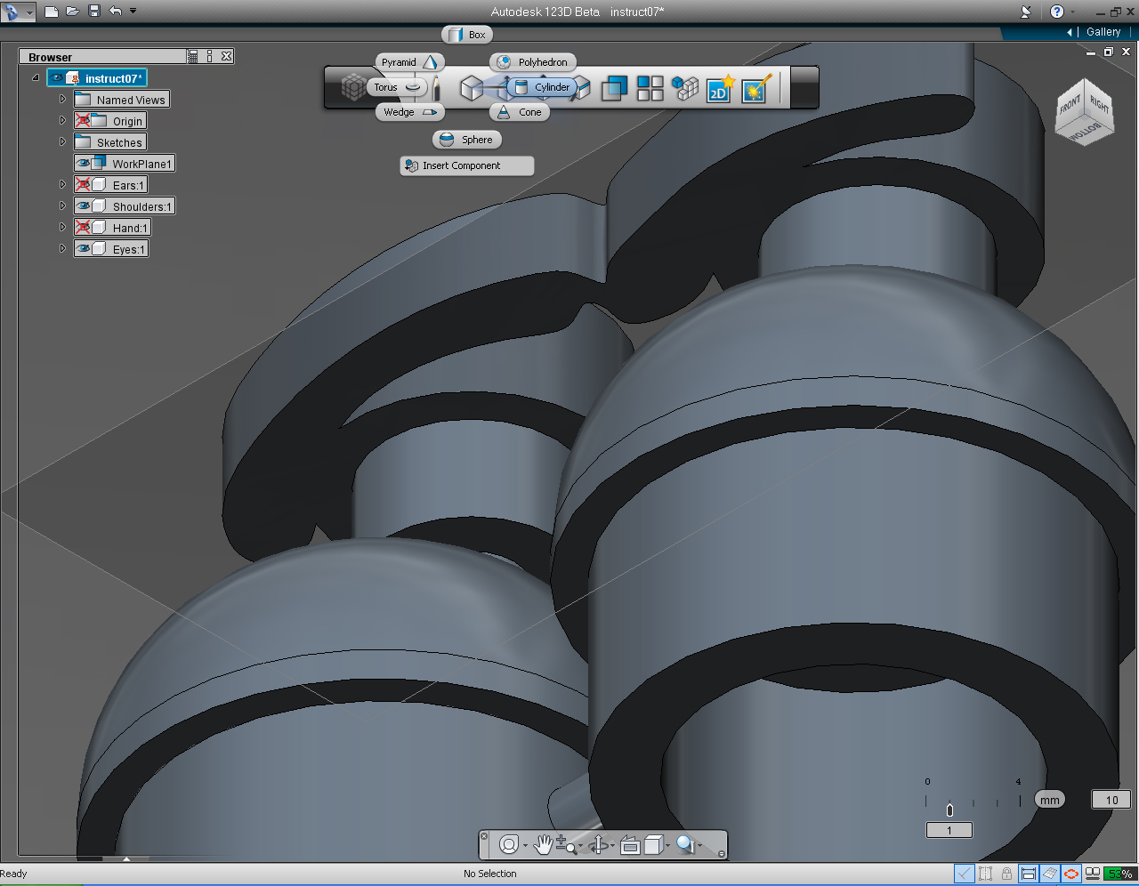
And these are the steps:
1. Hide the "Ears" and "Hands" Solid models.
2. Select the edge of the "View Cube" between FRONT and RIGHT and rotate the view as shown.
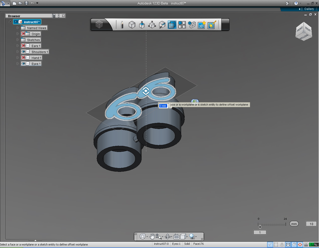
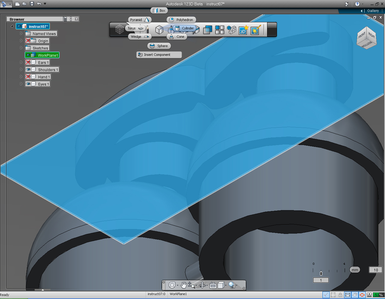
3. Select "Offset Plane" pill from "Construction" Marking Menu.
4. Leave the "Workplane" as it is, by press Enter key or right click.
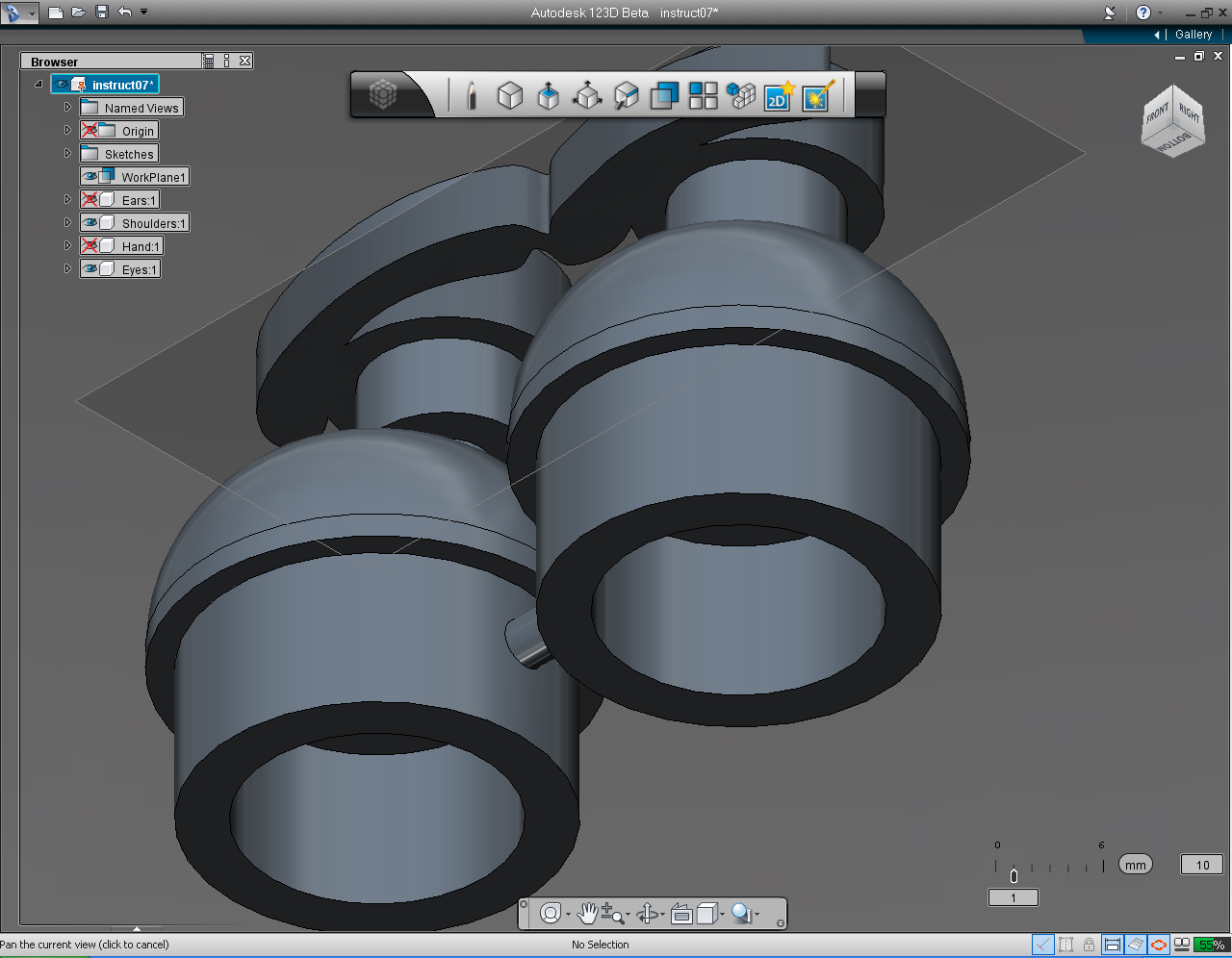
5. Use the Scroll (middle) mouse button to move the objects closer in the viewport.
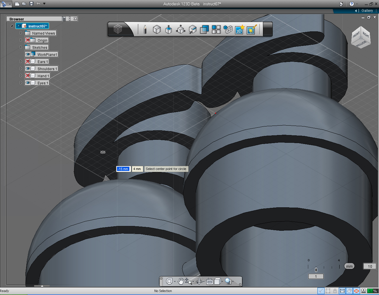
6. Select "Cylinder" pil on the "Primitive" Marking Menu.
7. Select new "Workplane" we just created.
8. Specify the center point of the cylinder at -16 and 4mm.
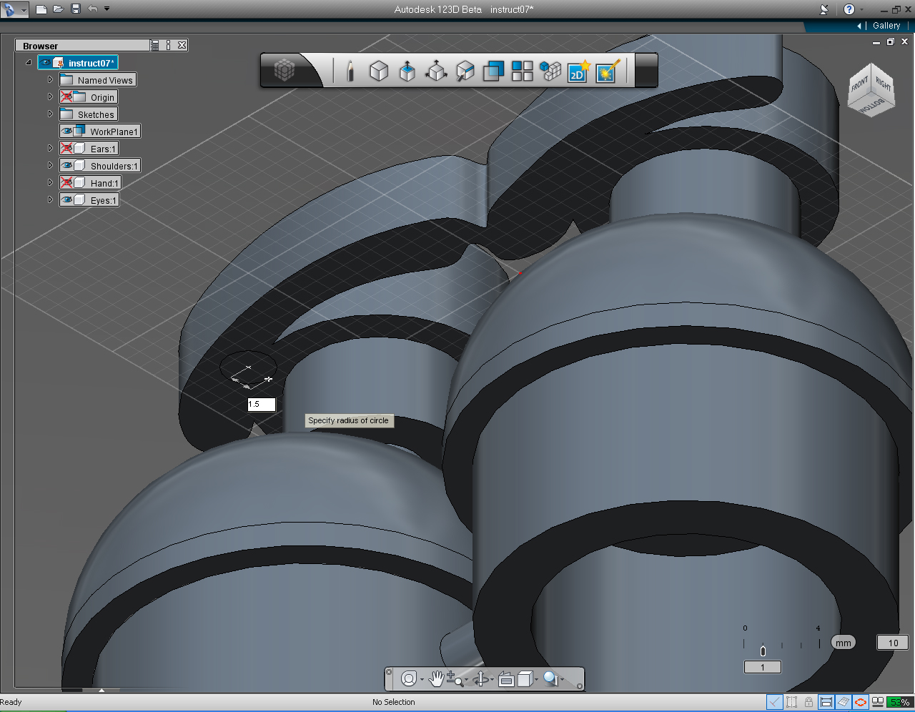
9. Specify the radius of the cylinder to 1.5mm
10. Drag the bi-directional arrow down to specify the height of the cylinder to 8mm
11. Right click the mouse to bring up Marking Menu, and select "Repeat.." pill. to create cylinder again.
12. Specify the center point of the cylinder at 7 and 4mm.
13. Specify the radius of the cylinder to 1.5mm
14. Drag the bi-directional arrow down to specify the height of the cylinder to 8mm
We got all the parts to join Shoulders and Eyes together.
15. Select one of the cylinder. Right click to bring up the Marking Menu. Then select "Solid Feature" -> "Combine"
16. Press Shift key while selecting all the separate Solid parts - Shoulders, Eyes, cylinder.
17. Commit the command, by right click again. And select "OK" pill.
Assemble 3D Models: Part 2 - Combine Ears and Hands
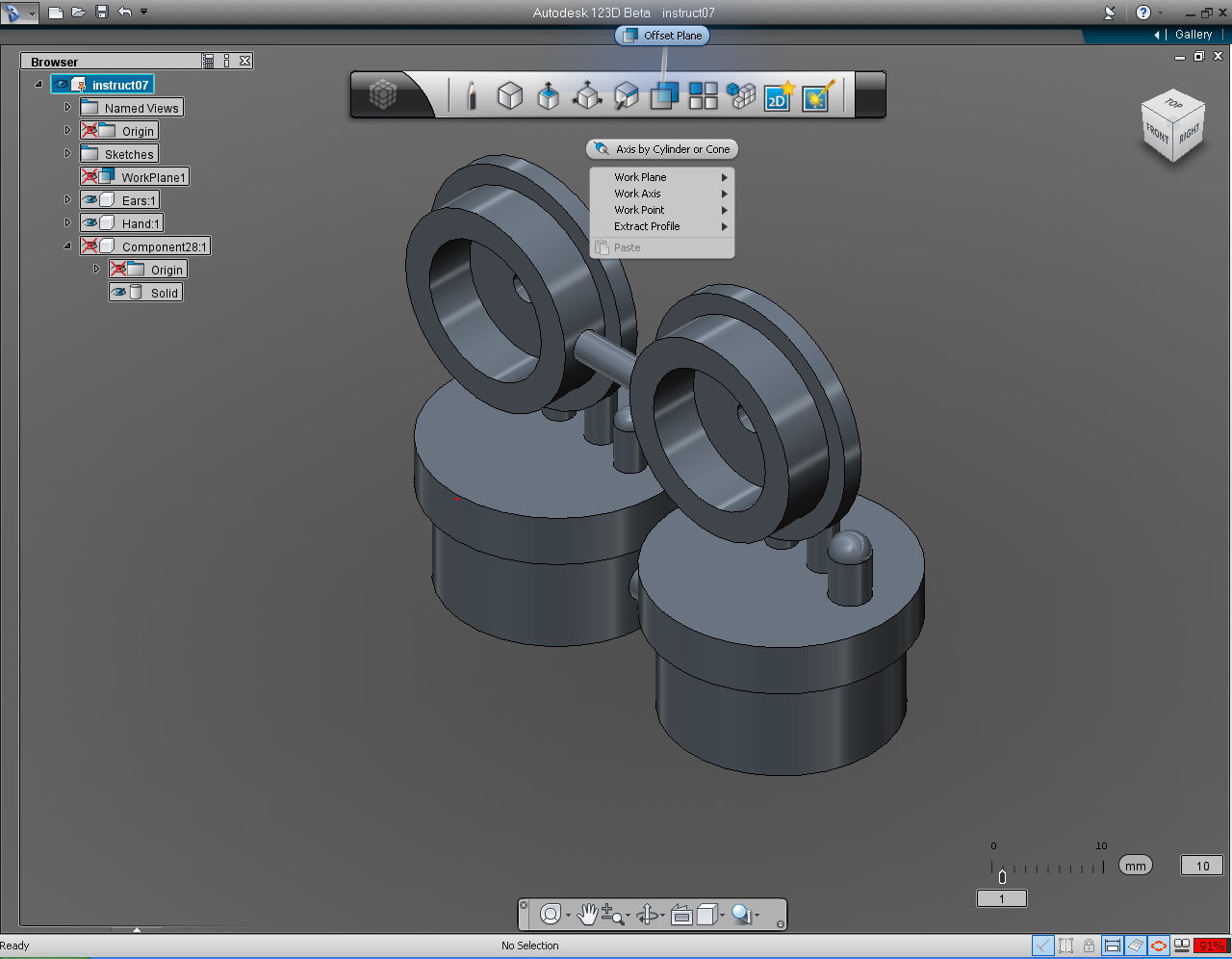
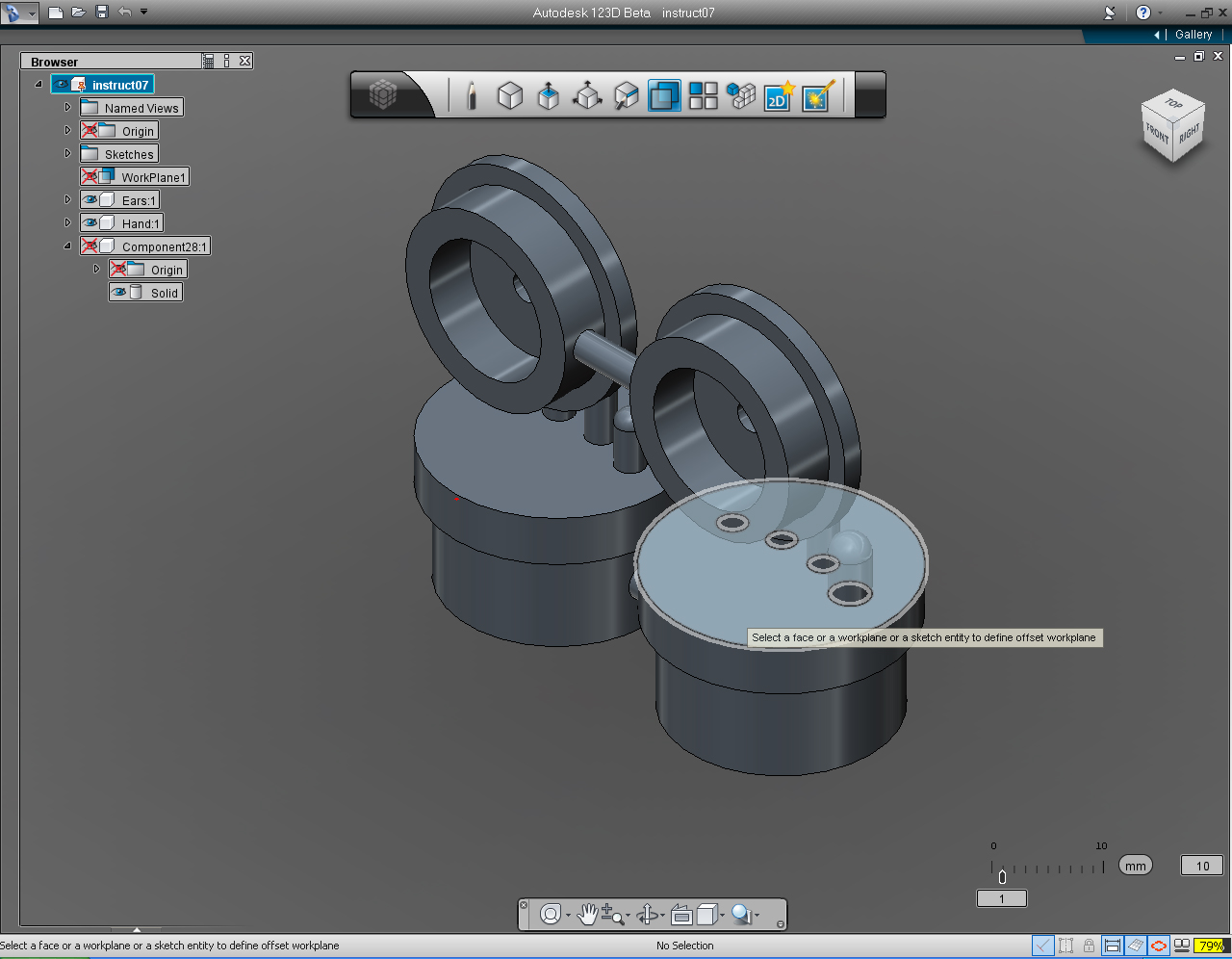
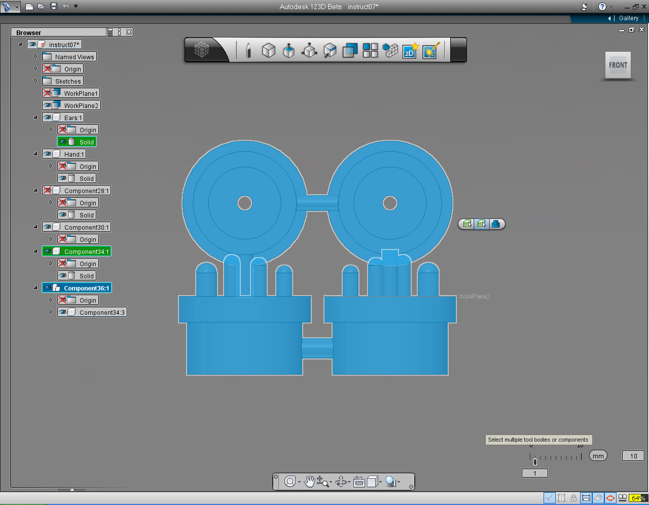
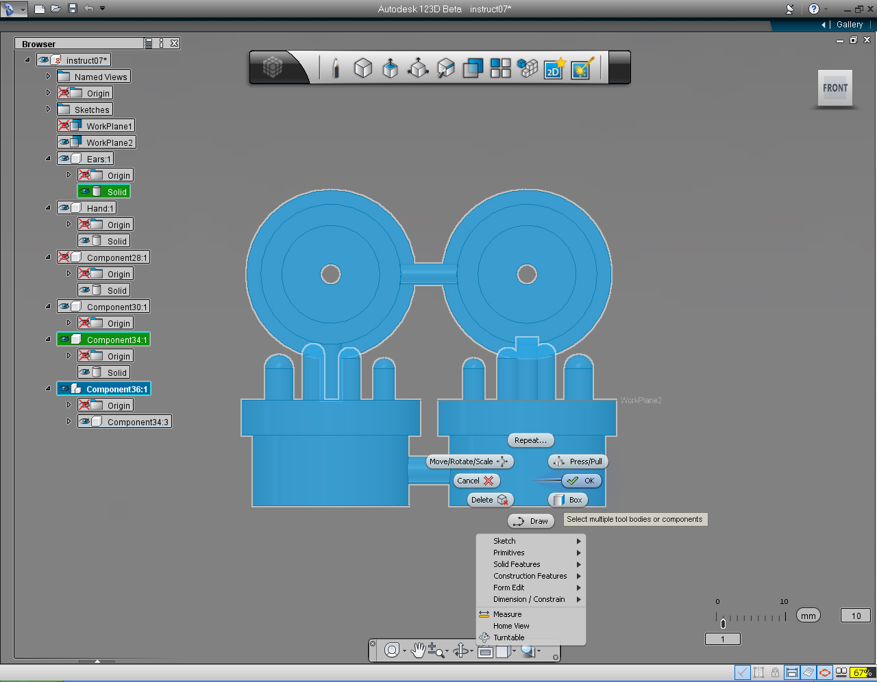
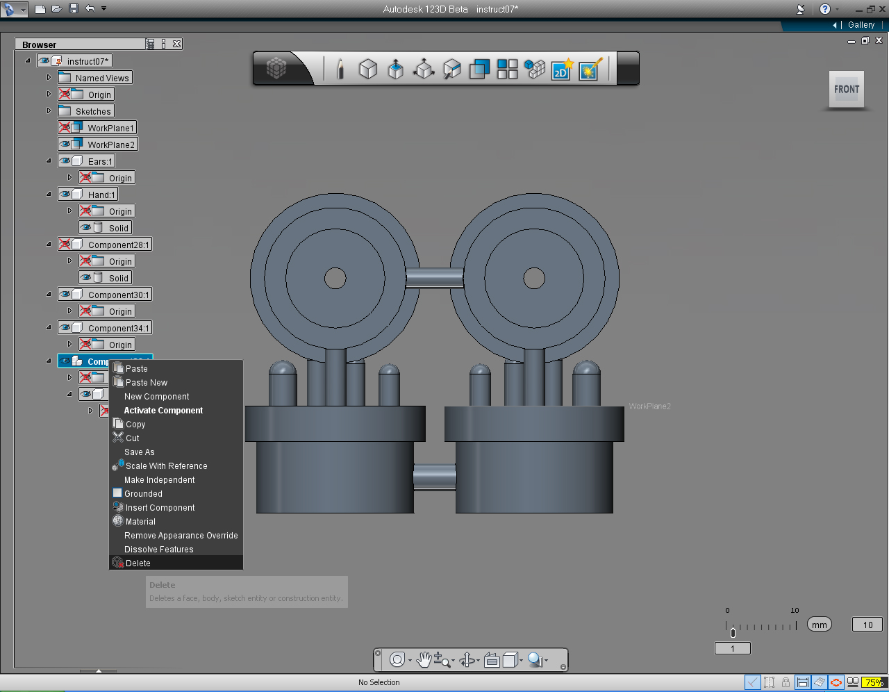
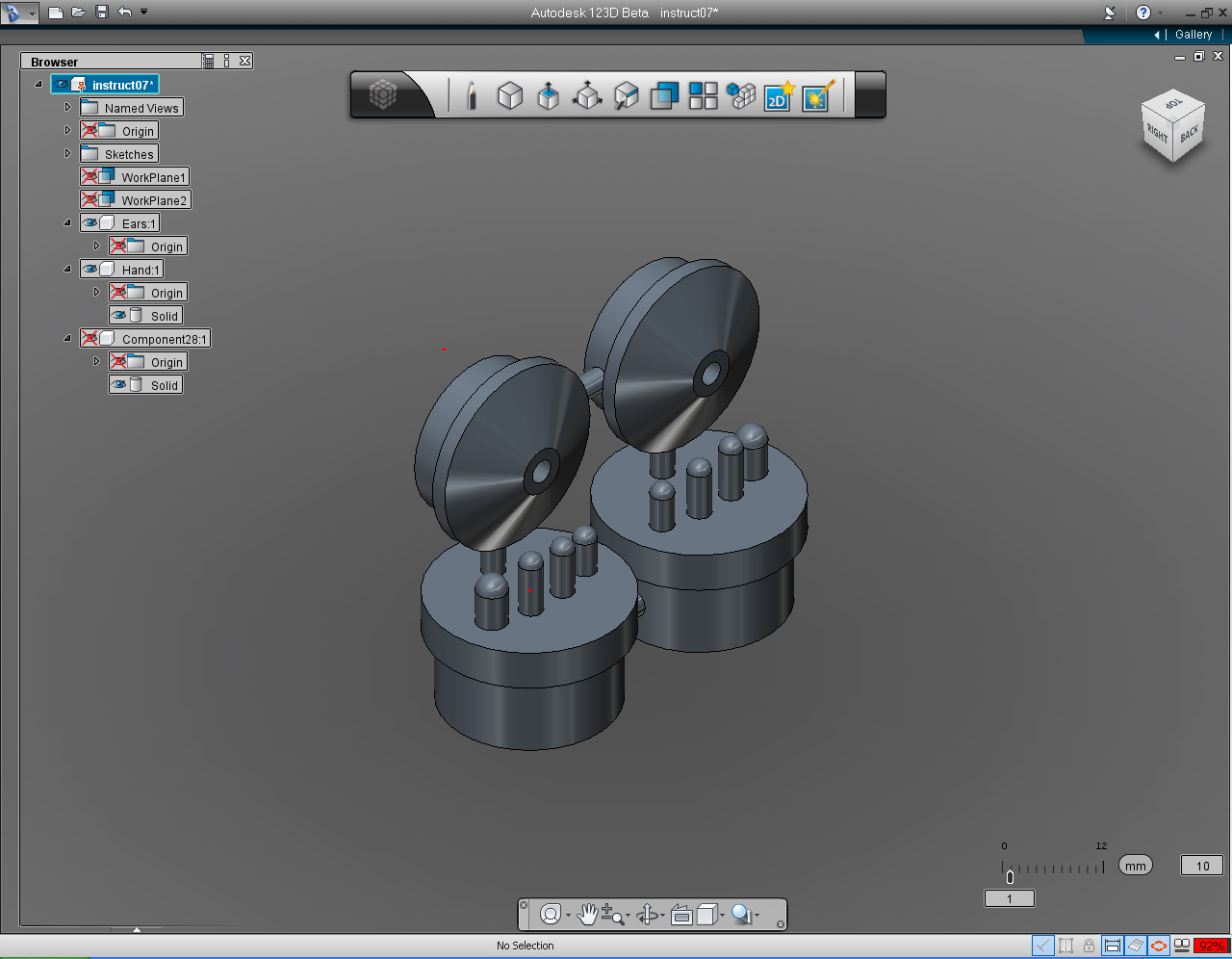
Summary of the commands to use in this step:
- "Offset Plane" in "Construction" Marking Menu
- "Cylinder" in the "Primitive" Marking Menu or bucket.
- "New Component"
- "Copy"
- "Solid Feature" -> "Combine"
- "Delete"
And these are the steps:
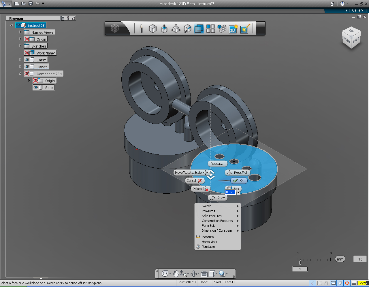
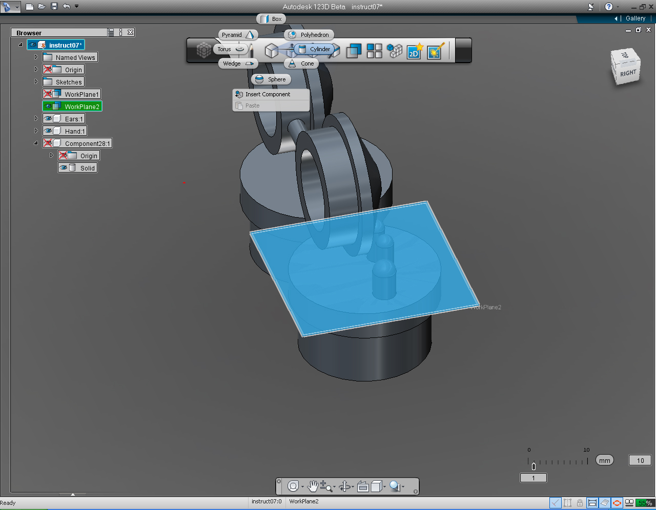
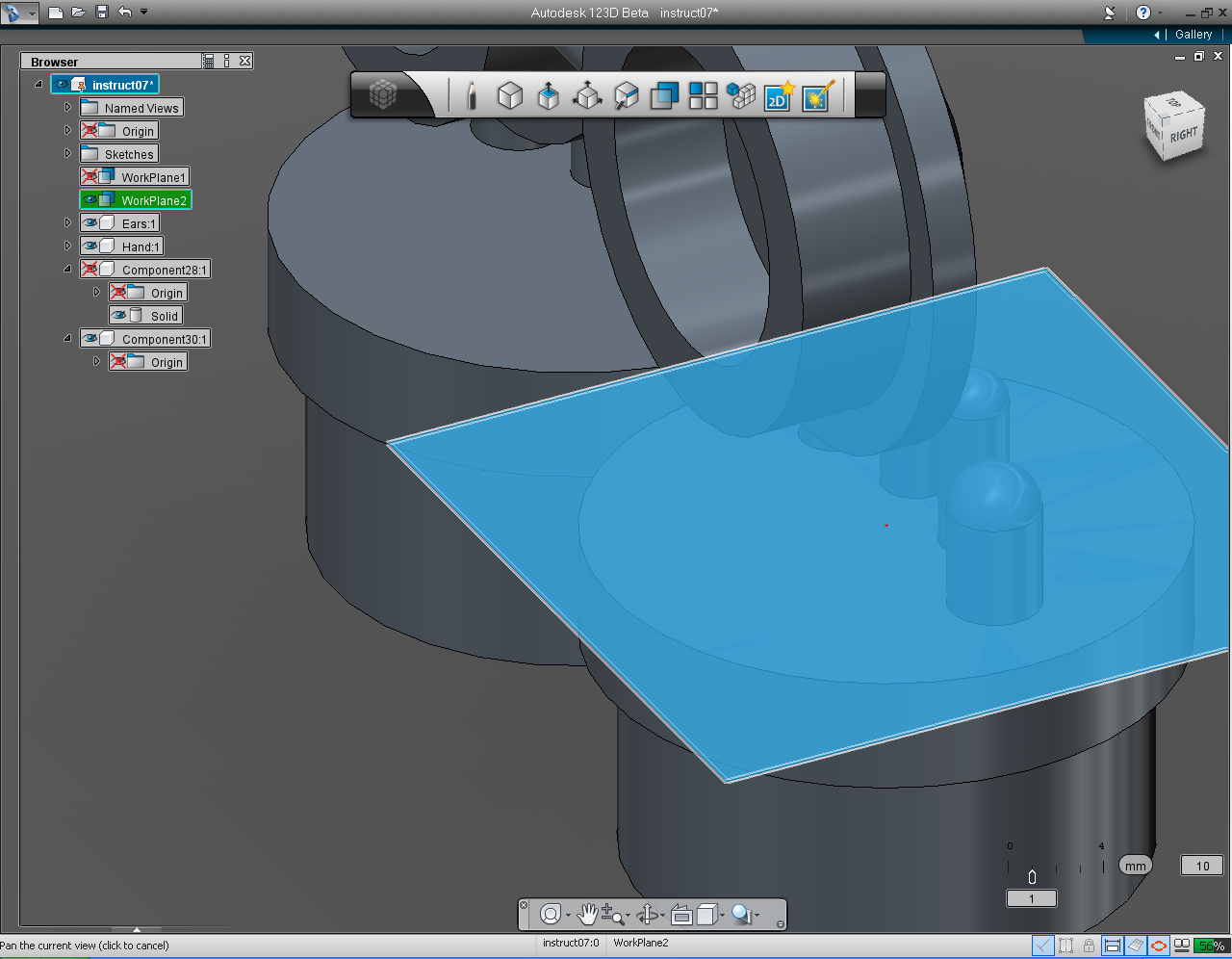
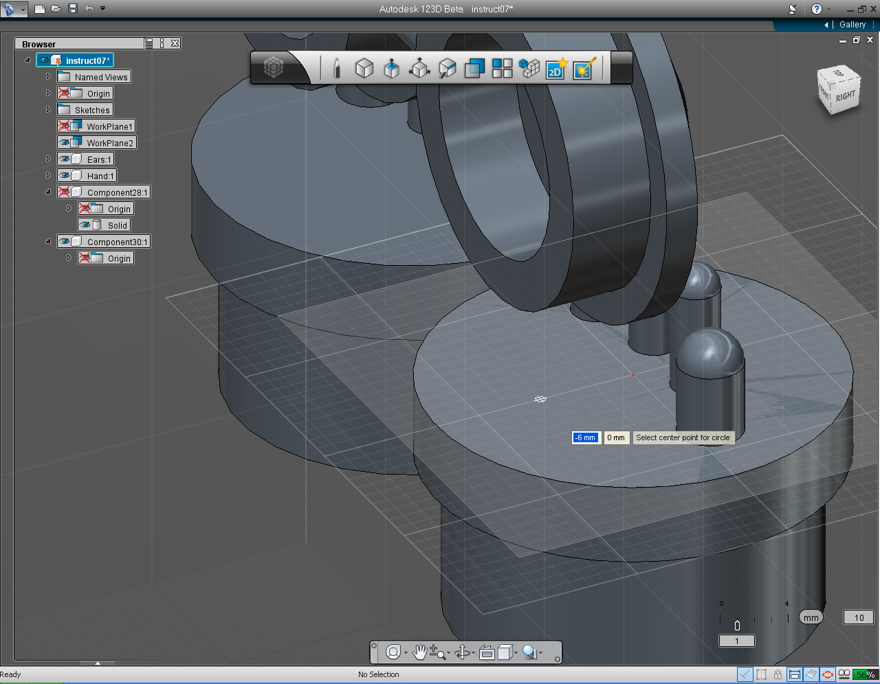
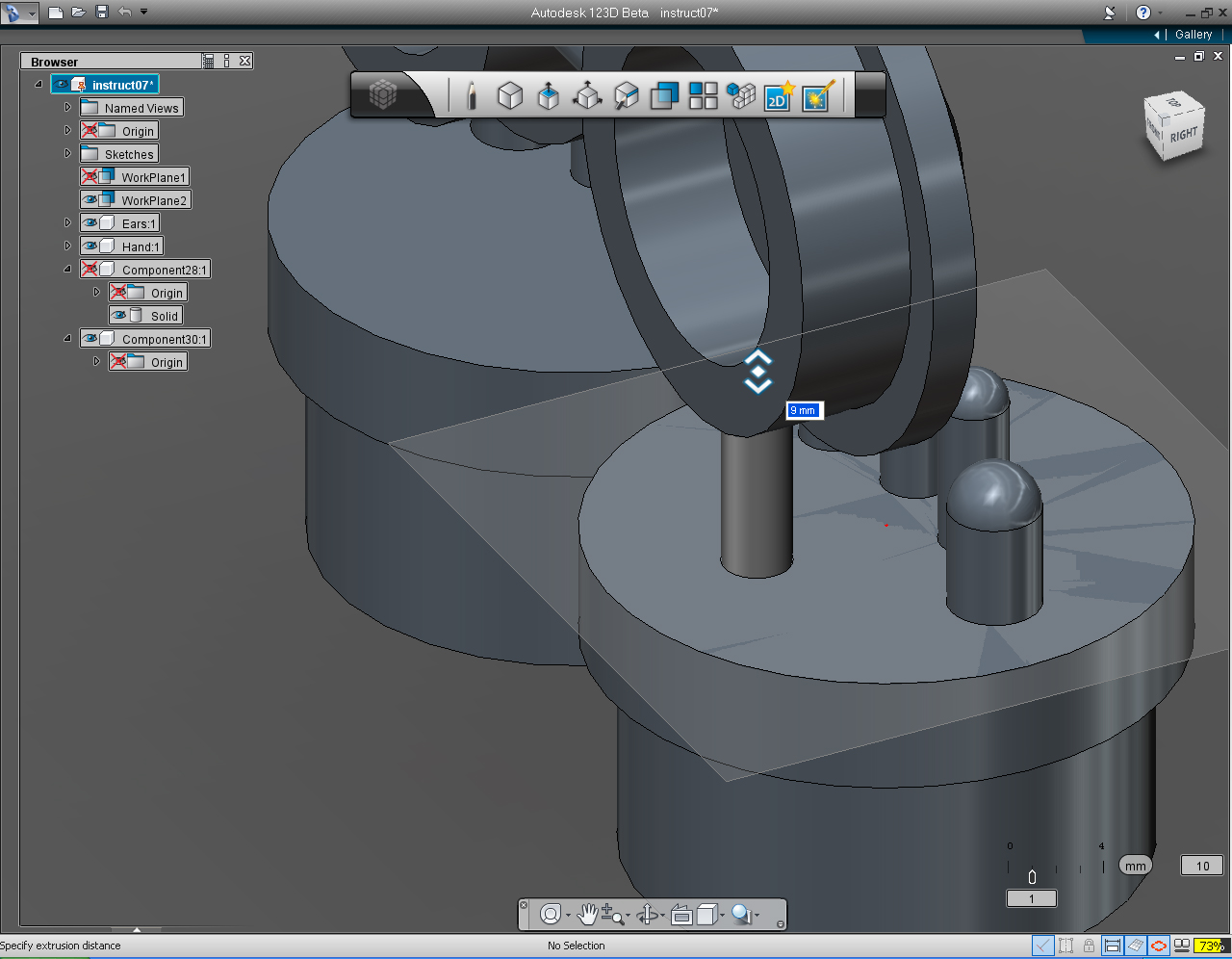
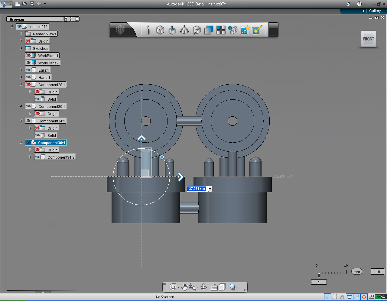
1. Hide "Workplane1" and previously joined solid model (Shoulders, and Eyes), leave only Hands and Ears on the screen.
2. Select "Offset Plane" in "Construction" Marking Menu to create new "Work Plane"
3. Move mouse cursor over one of the Hand top surface, and left click.
4. Right click to bring up Marking Menu, select "OK" pill to commit command.
5. Select "Cylinder" pill in the "Primitive" Marking Menu.
6. Adjust the screen so we can see the working plane closer, using "View Cube" or "Orbit" on the "Navigation" Tool Bar.
7. Start to draw cylinder by specify the center of cylinder at -6, 0
8. Specify the height of the cylinder to 9mm
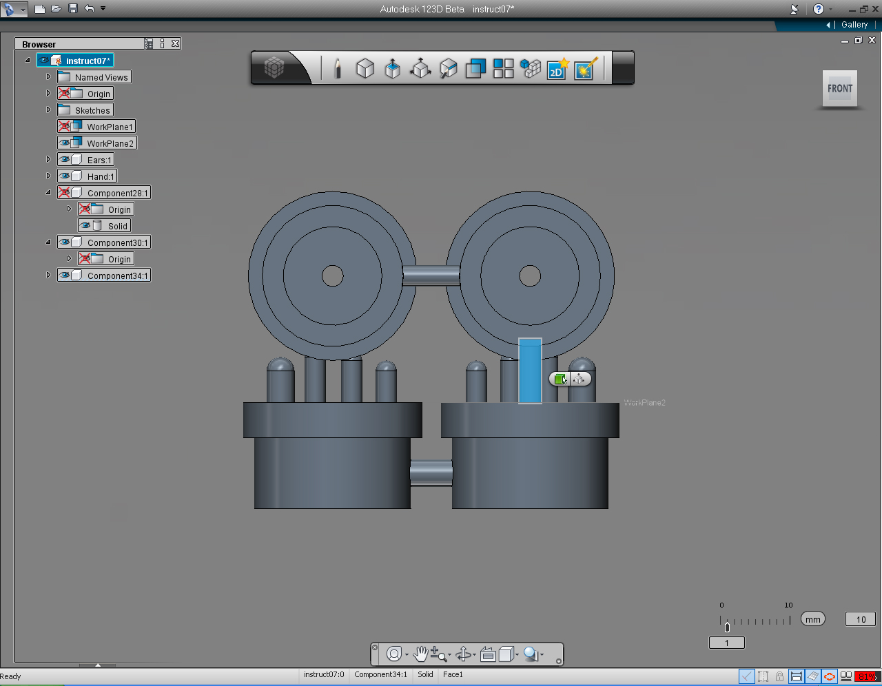
9. Change view to FRONT.
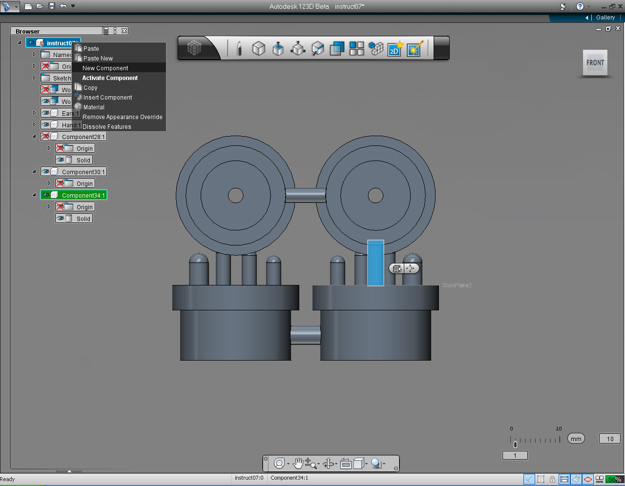
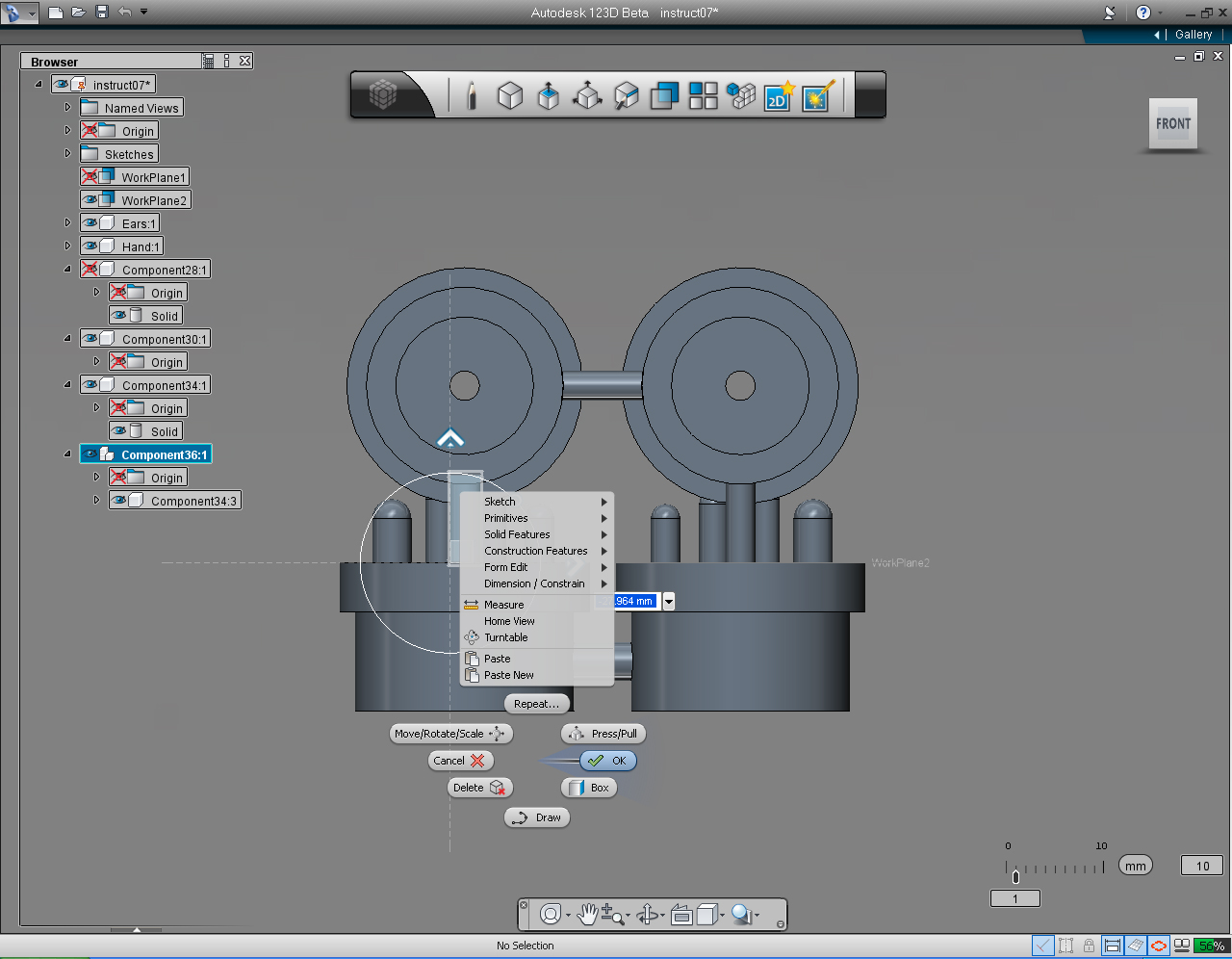
10. Right click at the Parent item on the "Feature Browser" list, select "New Component". And also select "Copy" command on the list.
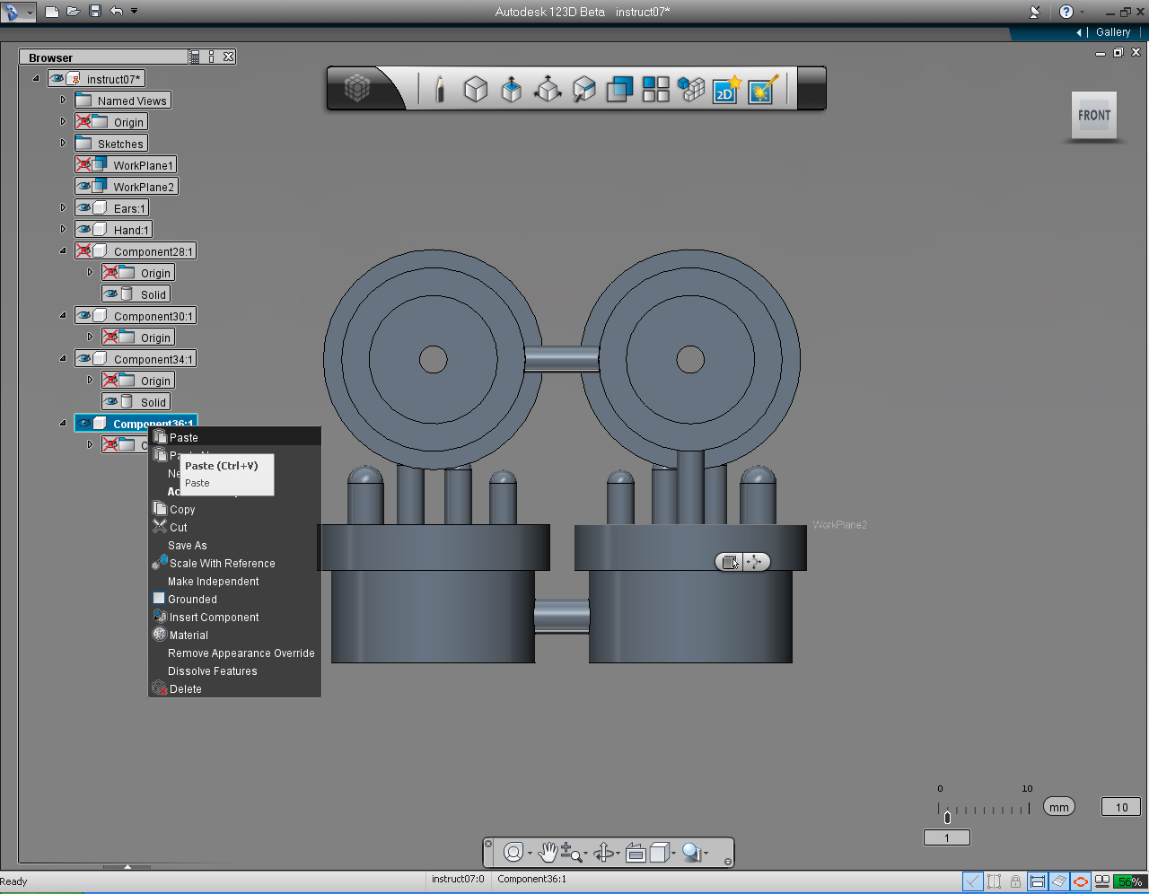
11. Click at newly create component, and right click the mouse to bring up commands list. Select "Paste" command
12. Drag the Horizontal Arrow to the left to approximately at the center of left hand.
13. Right click to bring up Marking Menu, select "OK" pill to commit command.
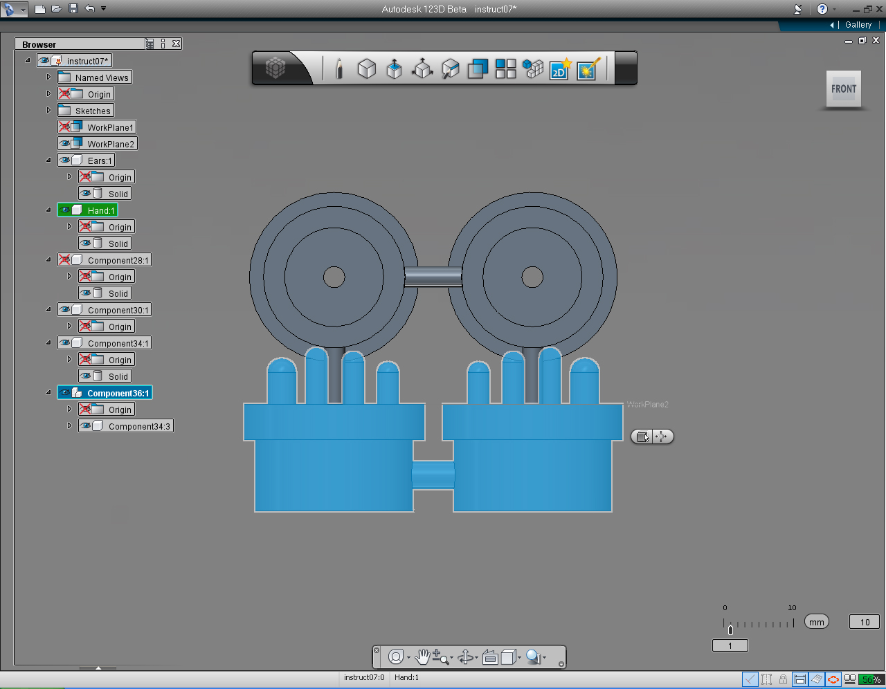
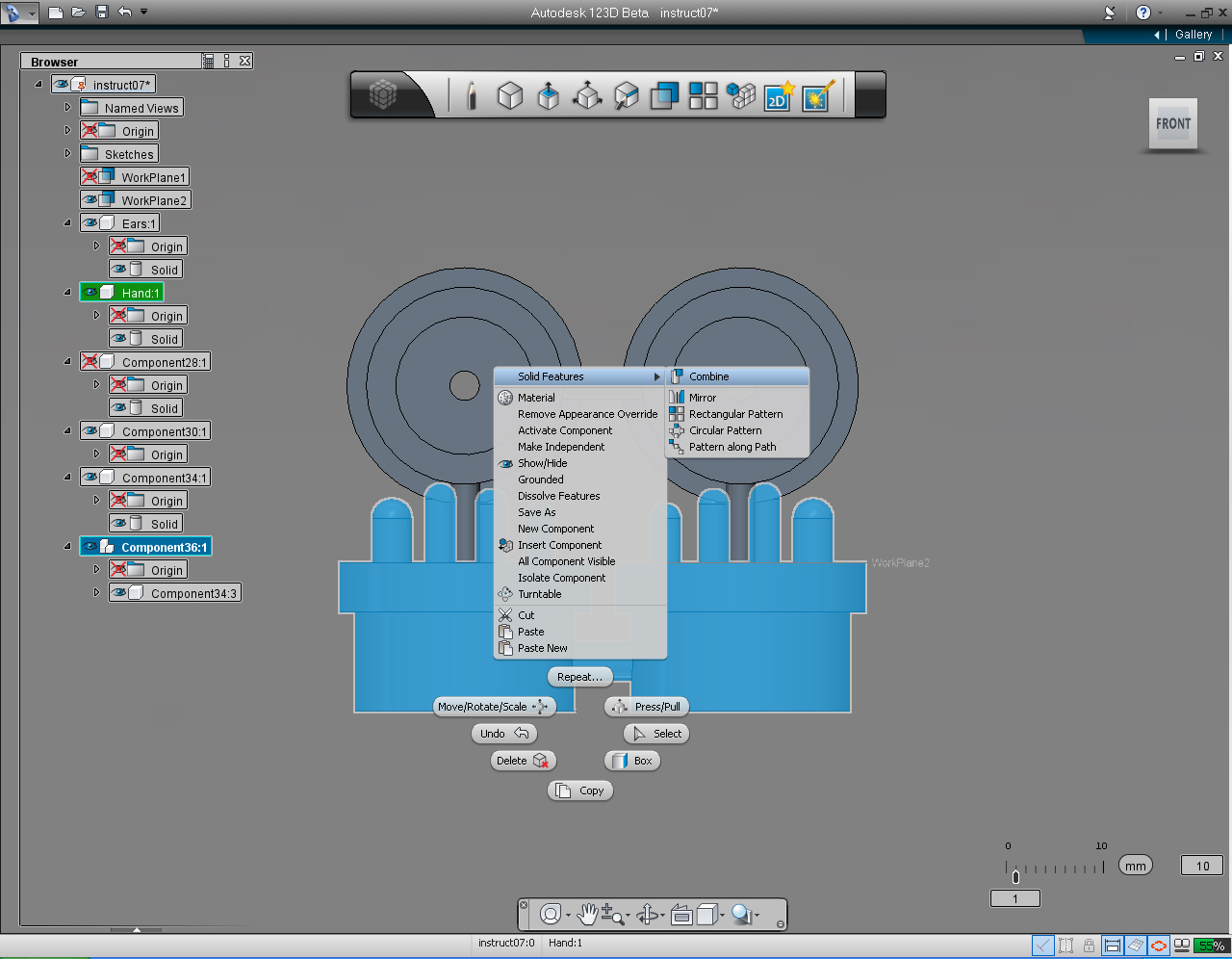
14. Select "Hands" model on the "Feature Browser" Menu
15. Right click to bring up Marking Menu, select "Solid Feature" -> "Combine"
16. Hold down the Shift key, and select Ears, and two cylinders we created earlier
17. Right click to bring up Marking Menu, select "OK" pill to commit command.
18. Dropdown all the components, right click at an empty component (no Solid), and select "Delete" command to delete empty component.
Now we have Hands and Ears joined!
Assemble 3D Models: Part 2 - Make Parts As One
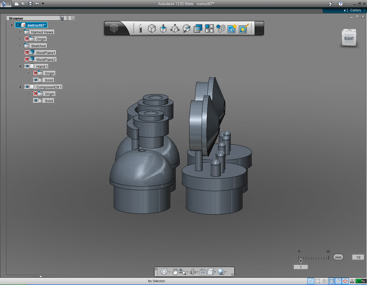
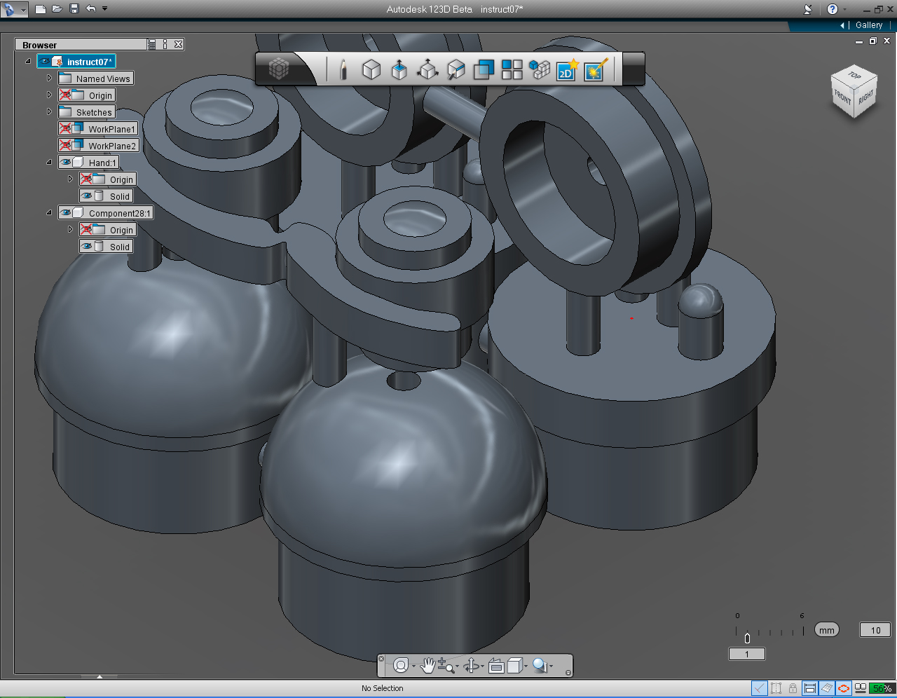
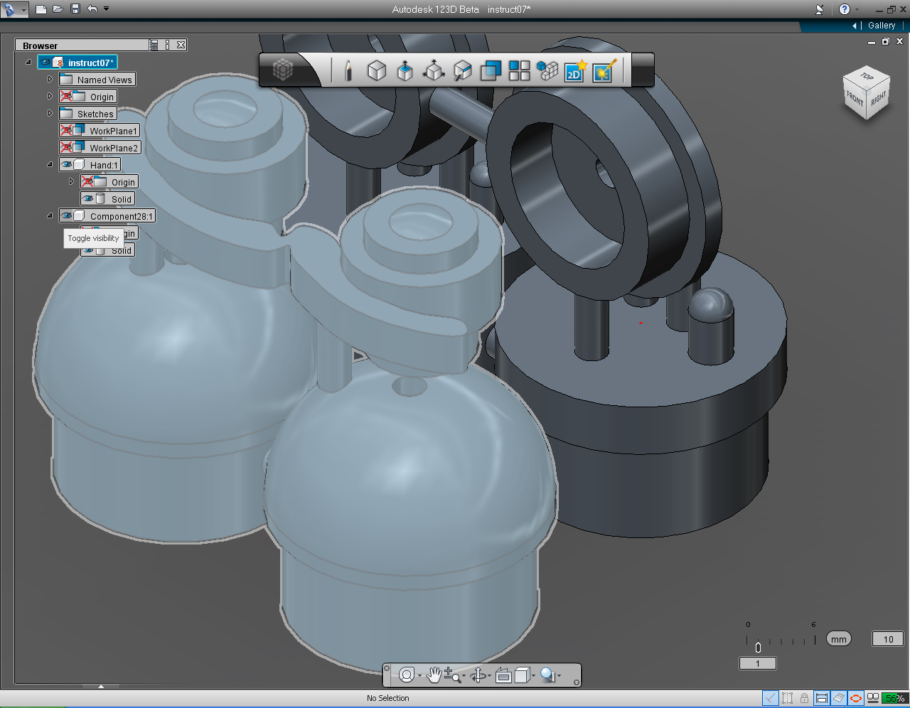
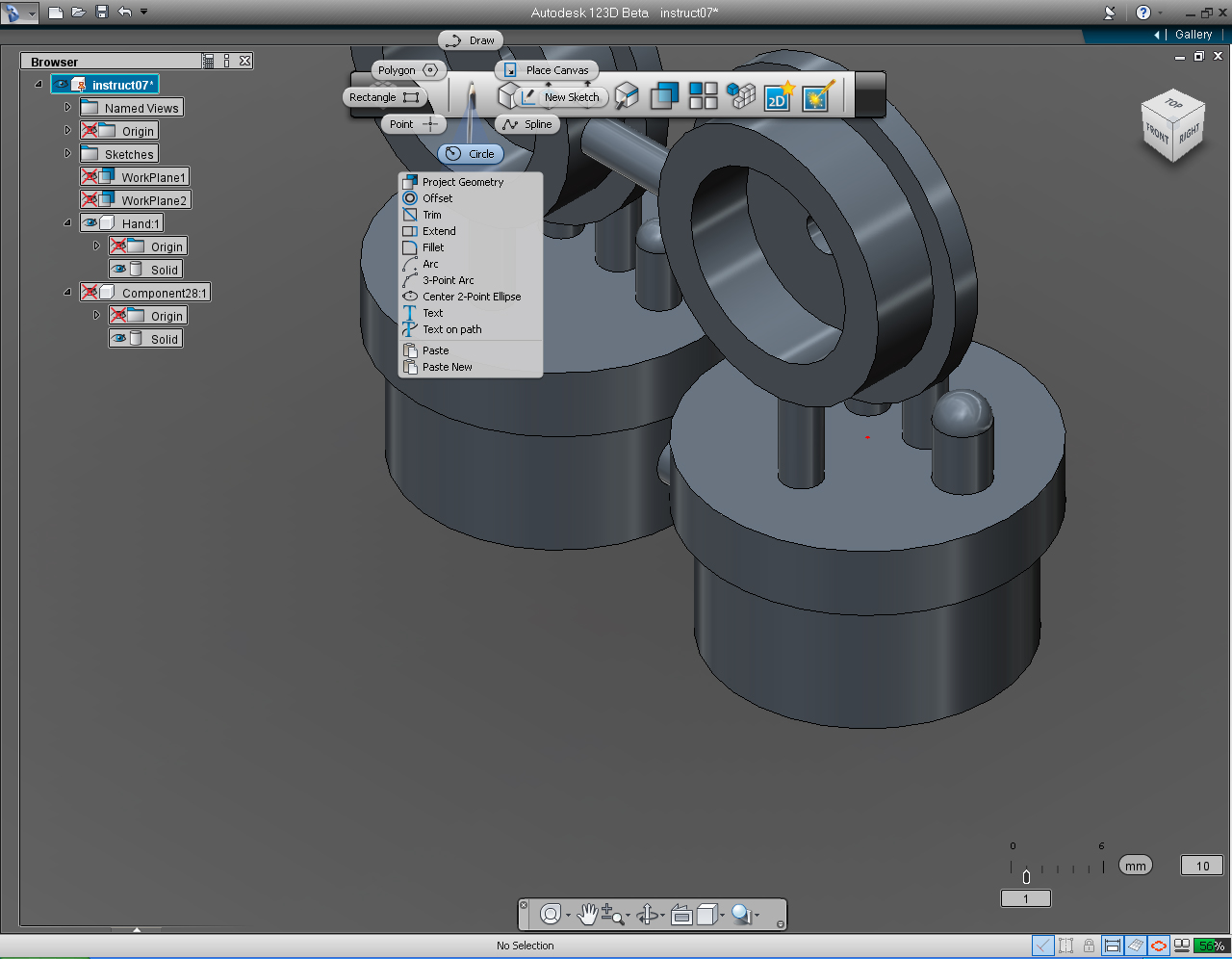
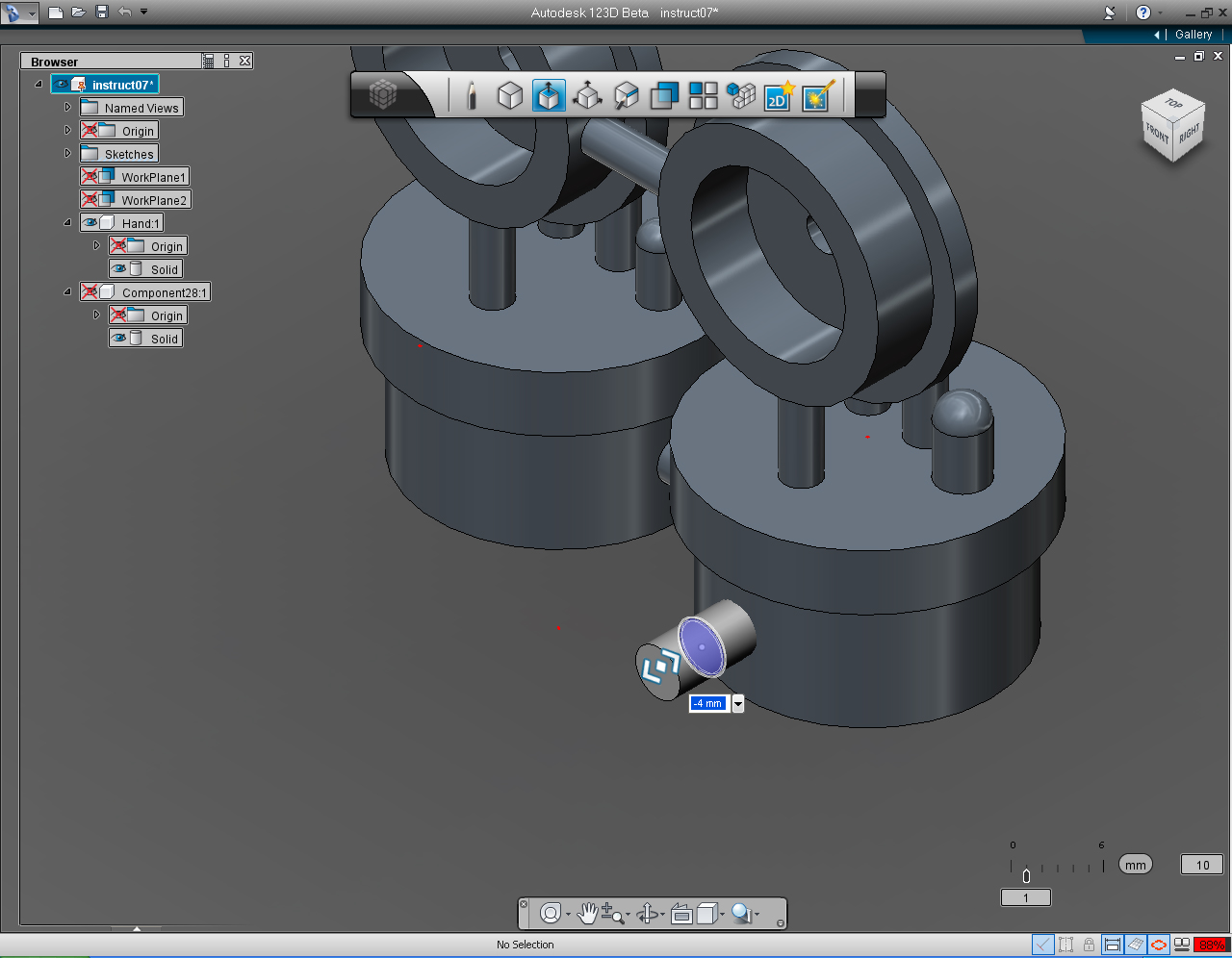
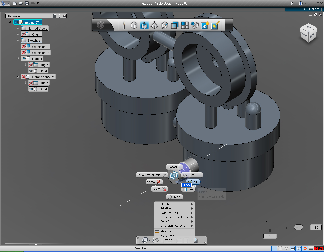
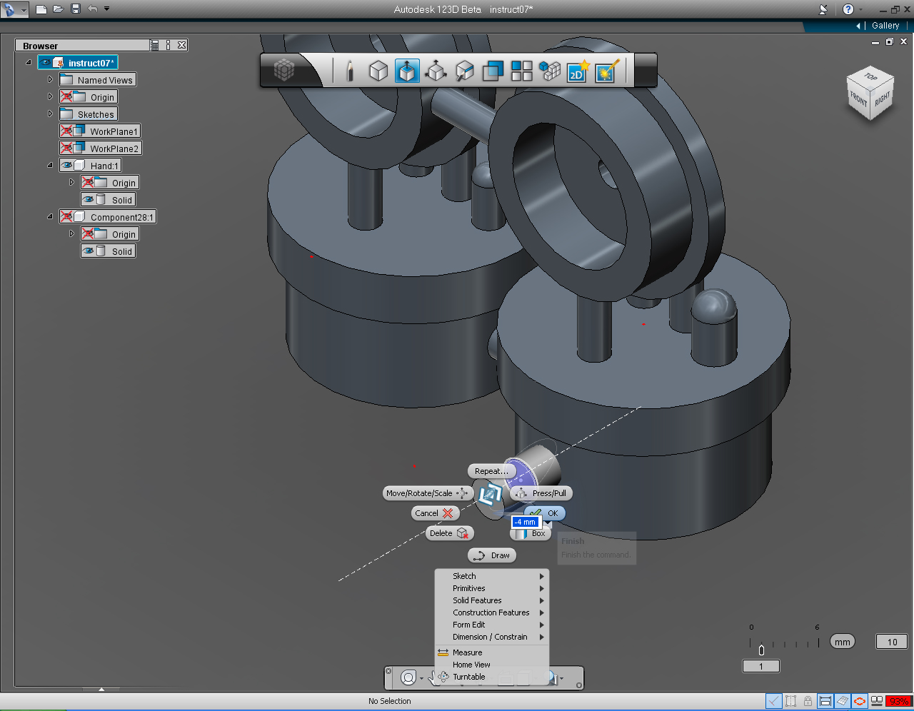
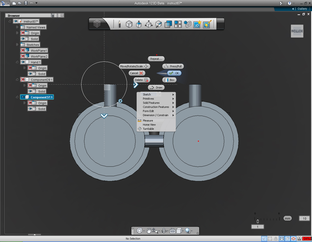
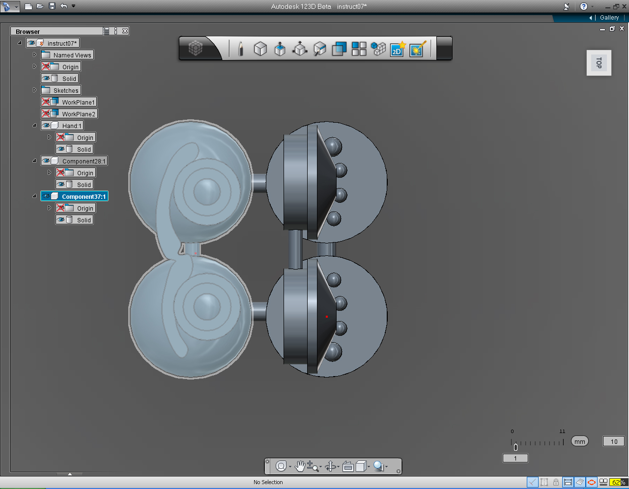
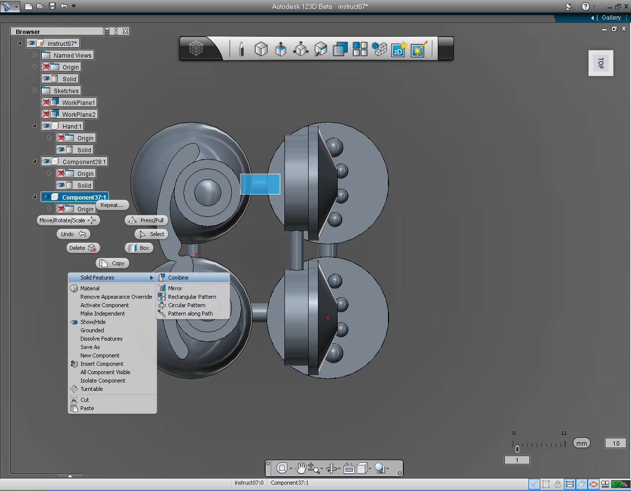
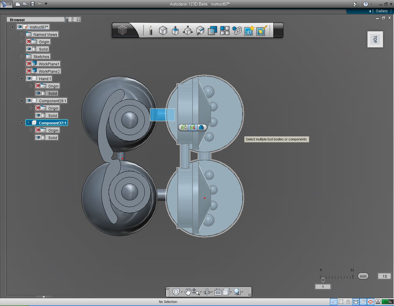
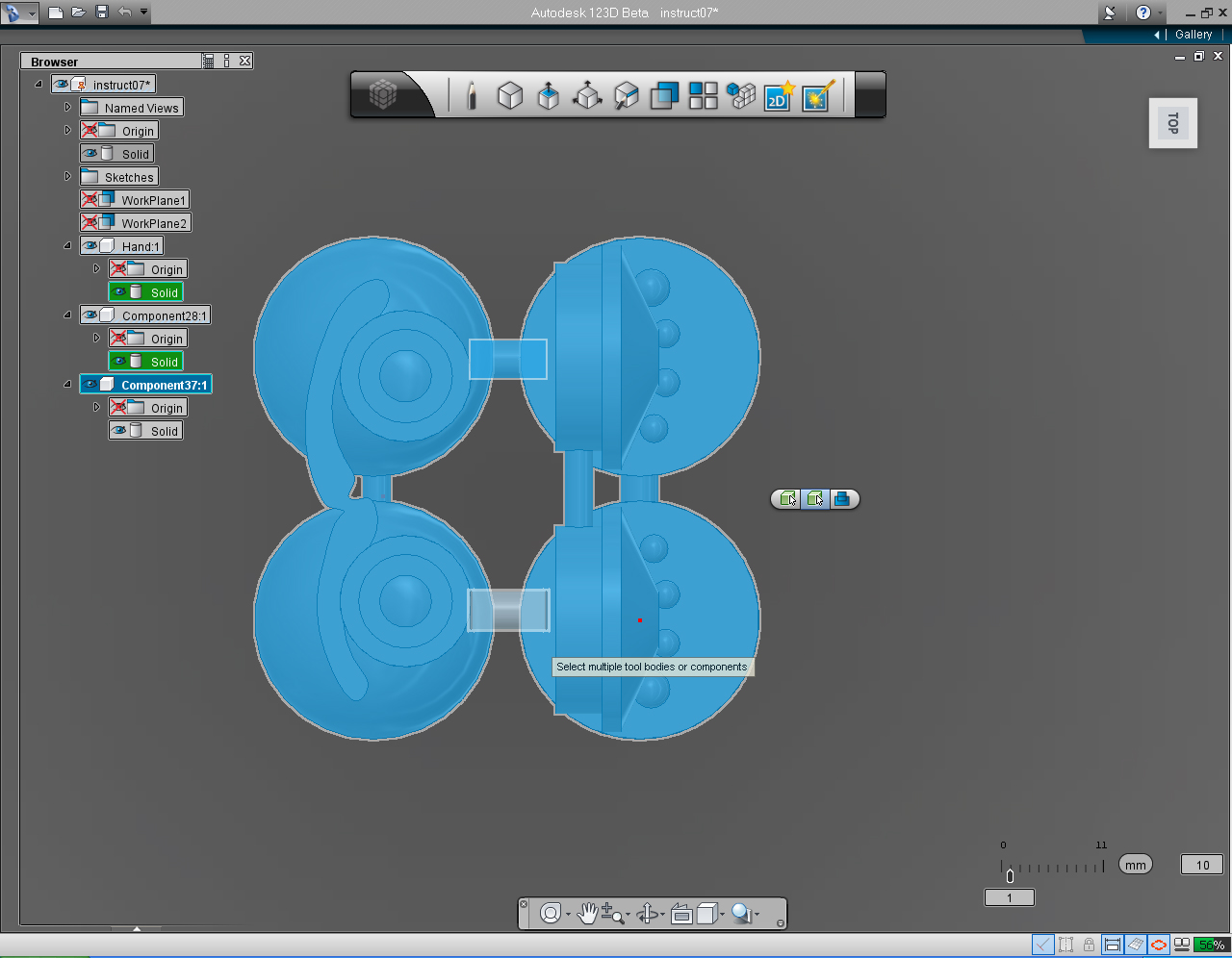
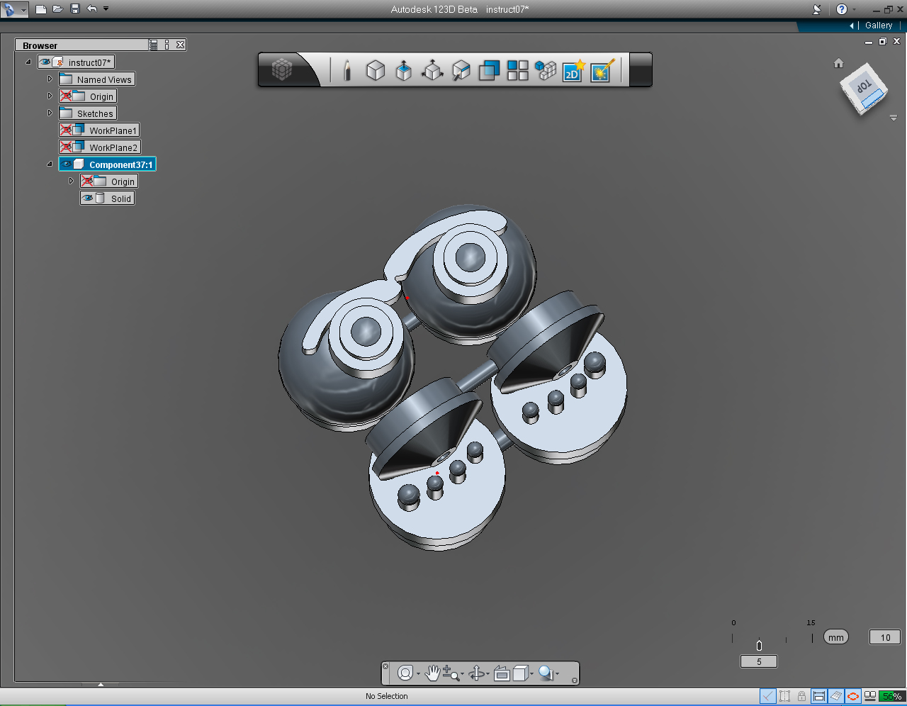

Summary of the commands to use in this step:
- "Offset Plane" in "Construction" Marking Menu
- "Cylinder" in the "Primitive" Marking Menu or bucket.
- "New Component"
- "Copy"
- "Solid Feature" -> "Combine"
- "Delete"
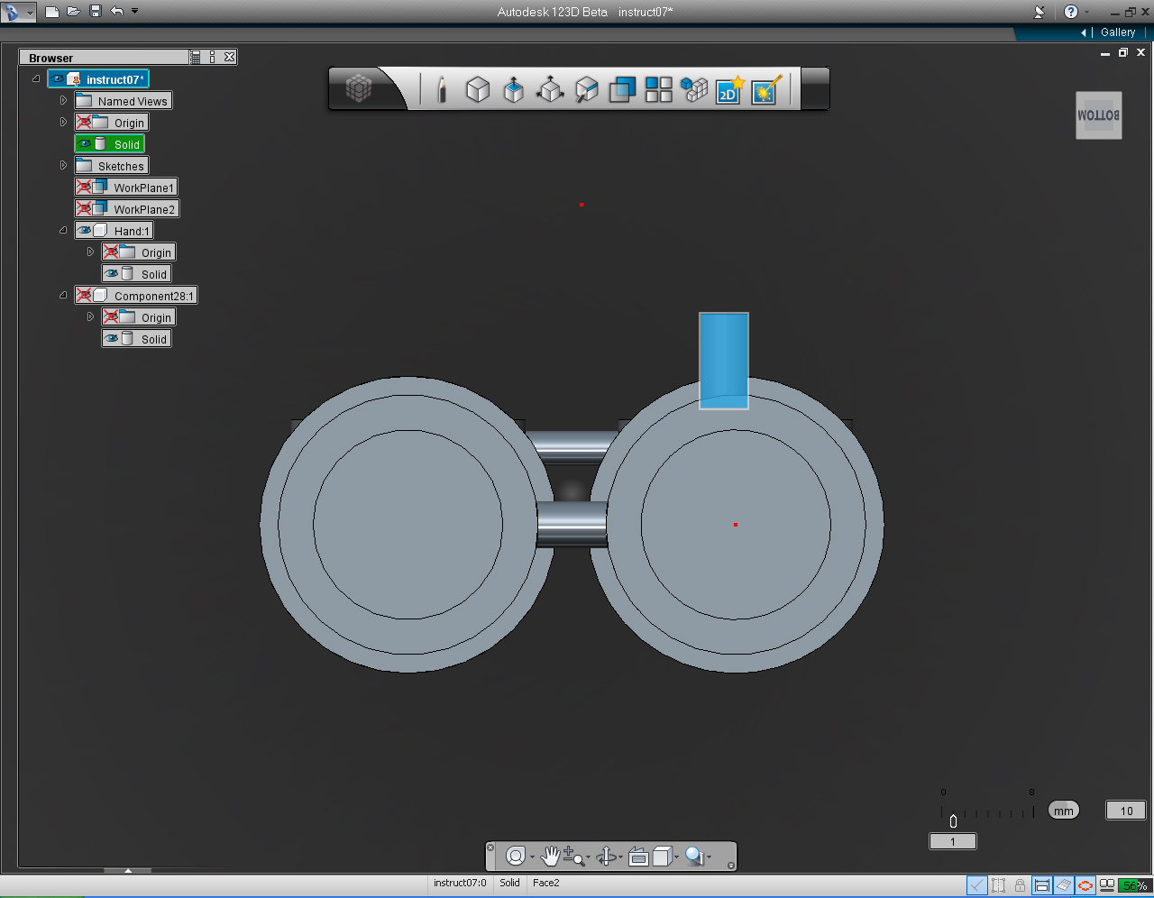
And these are the steps:
1. Unhide all solid models.
2. Use "Orbit" function and Scroll (middle) button to bring objects closer to the screen.
3. Hide the Shoulders and Eyes Solid model.
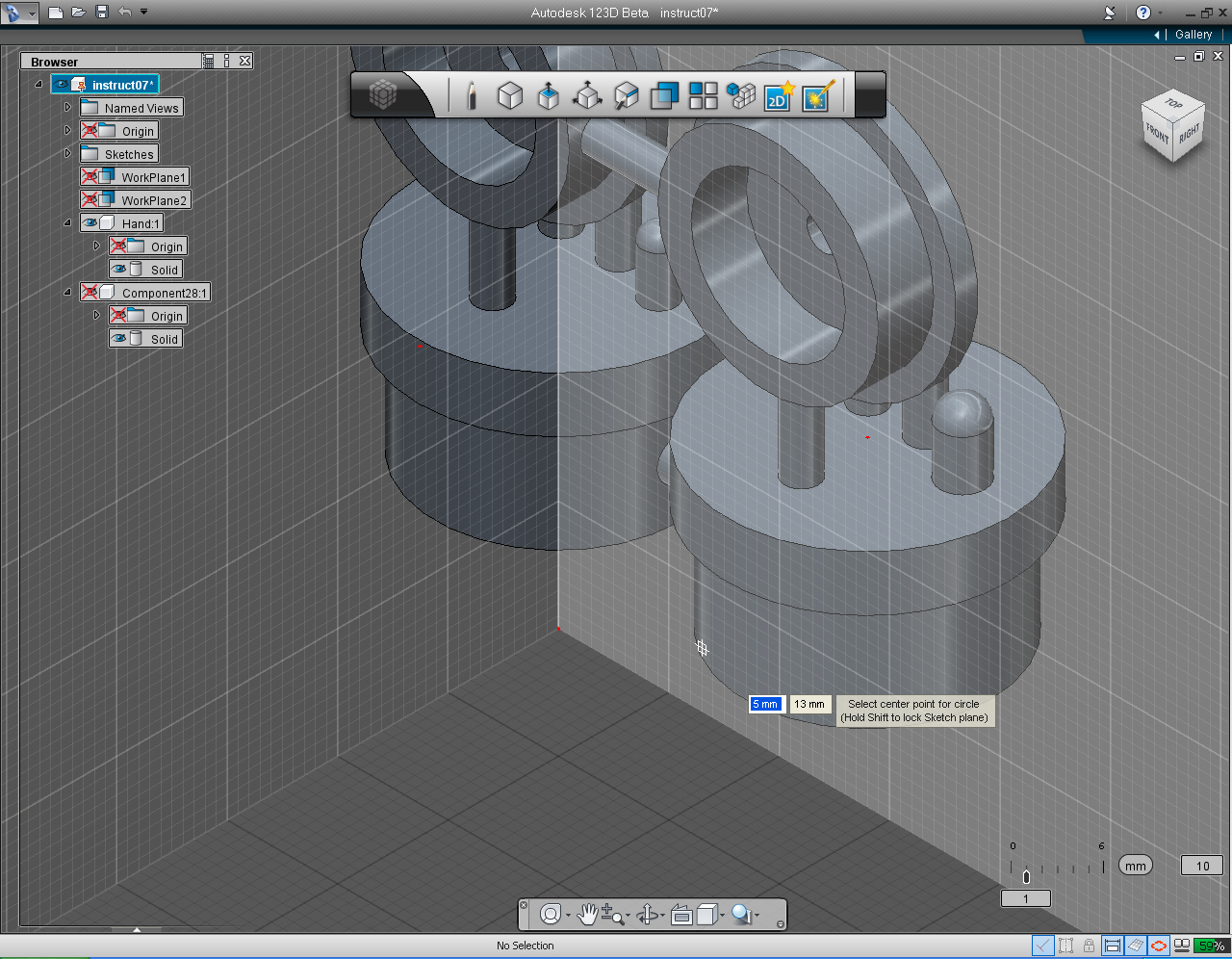
4. Select "Circle" pill from "Sketch" Marking Menu.
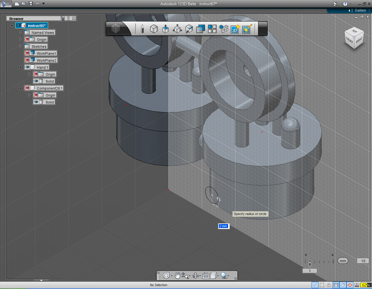
5. Move mouse over the FRONT plane and hold down Shift key. Specify the center point of circle at 5, 13 mm.
6. Specify the radius of the circle to 2mm.
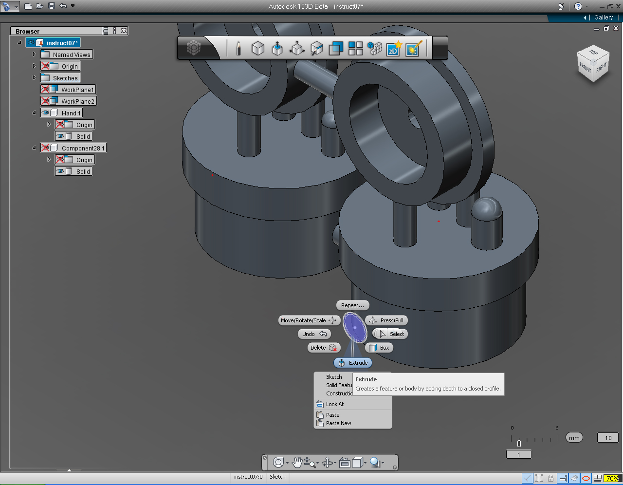
7. Right click to bring up Marking Menu and select "Extrude"
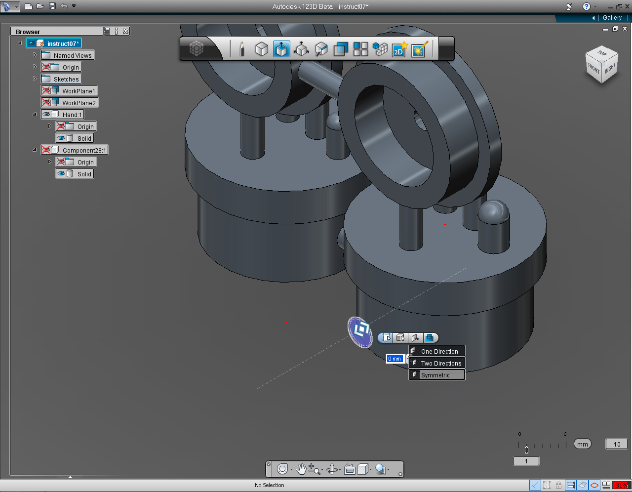
8. Click at the first icon of the pill, and select "Symmetric"
9. Drag the bi-directional arrow to specify the extrusion length of -4mm.
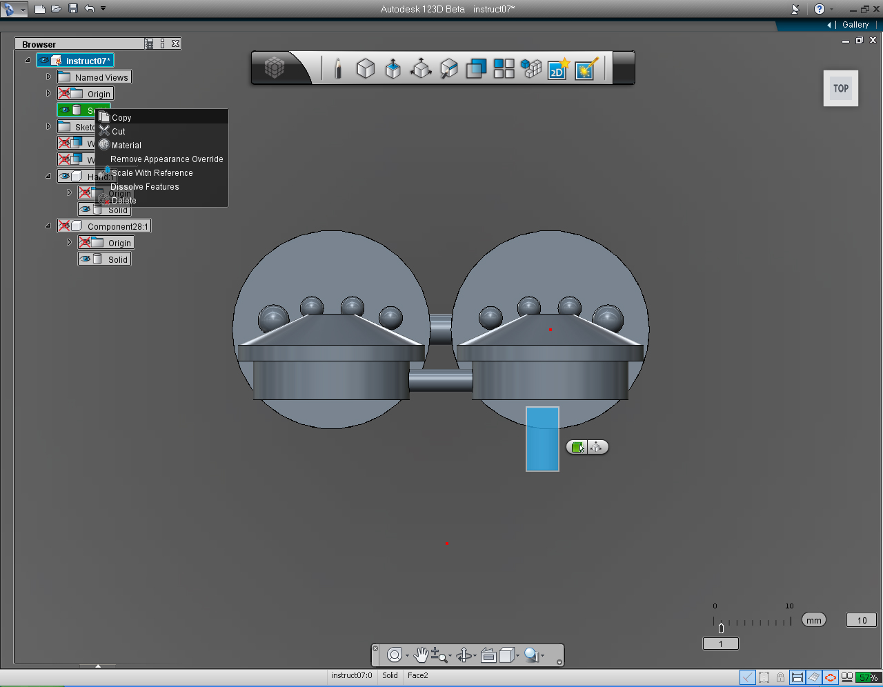
10. Change view to TOP view
11. Right click at newly created (extruded circle) Solid. Then select "Copy" from the list.
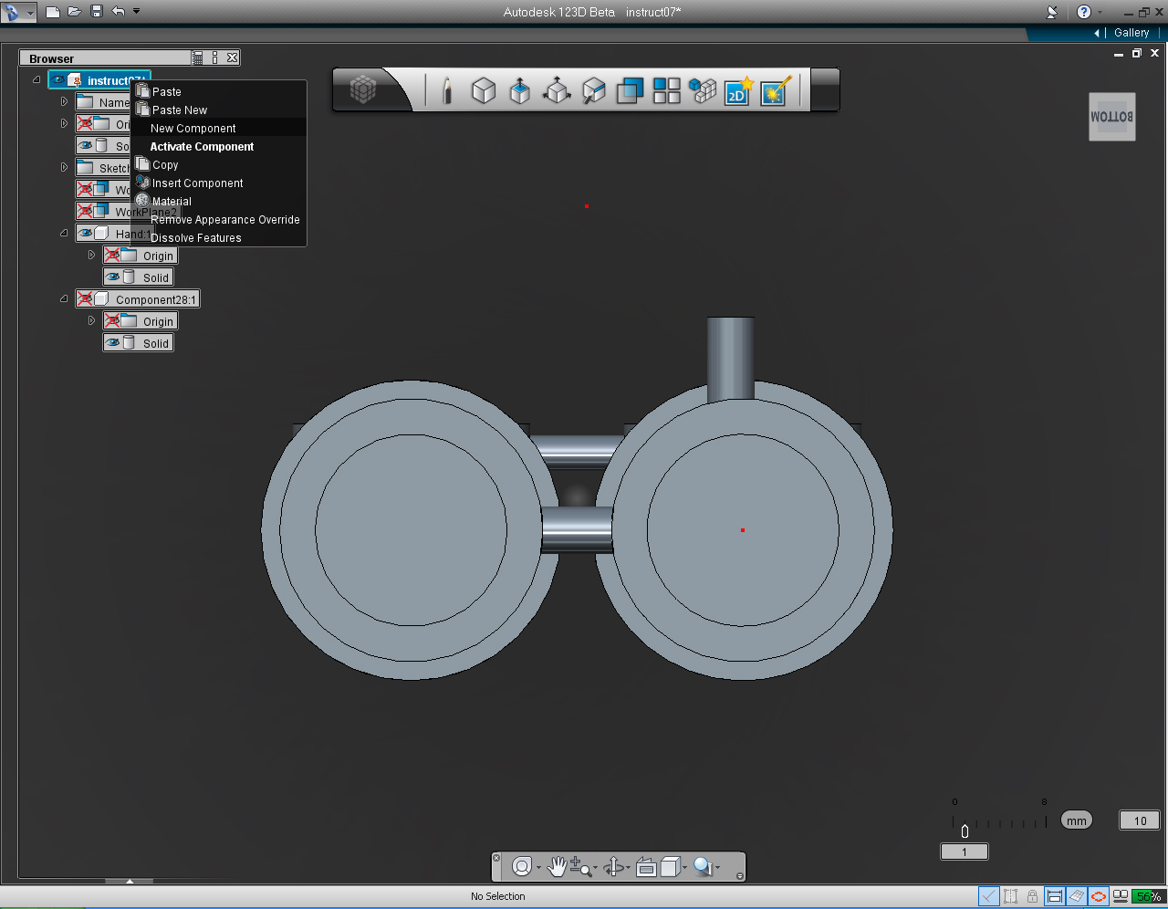
12. Change view to BOTTOM
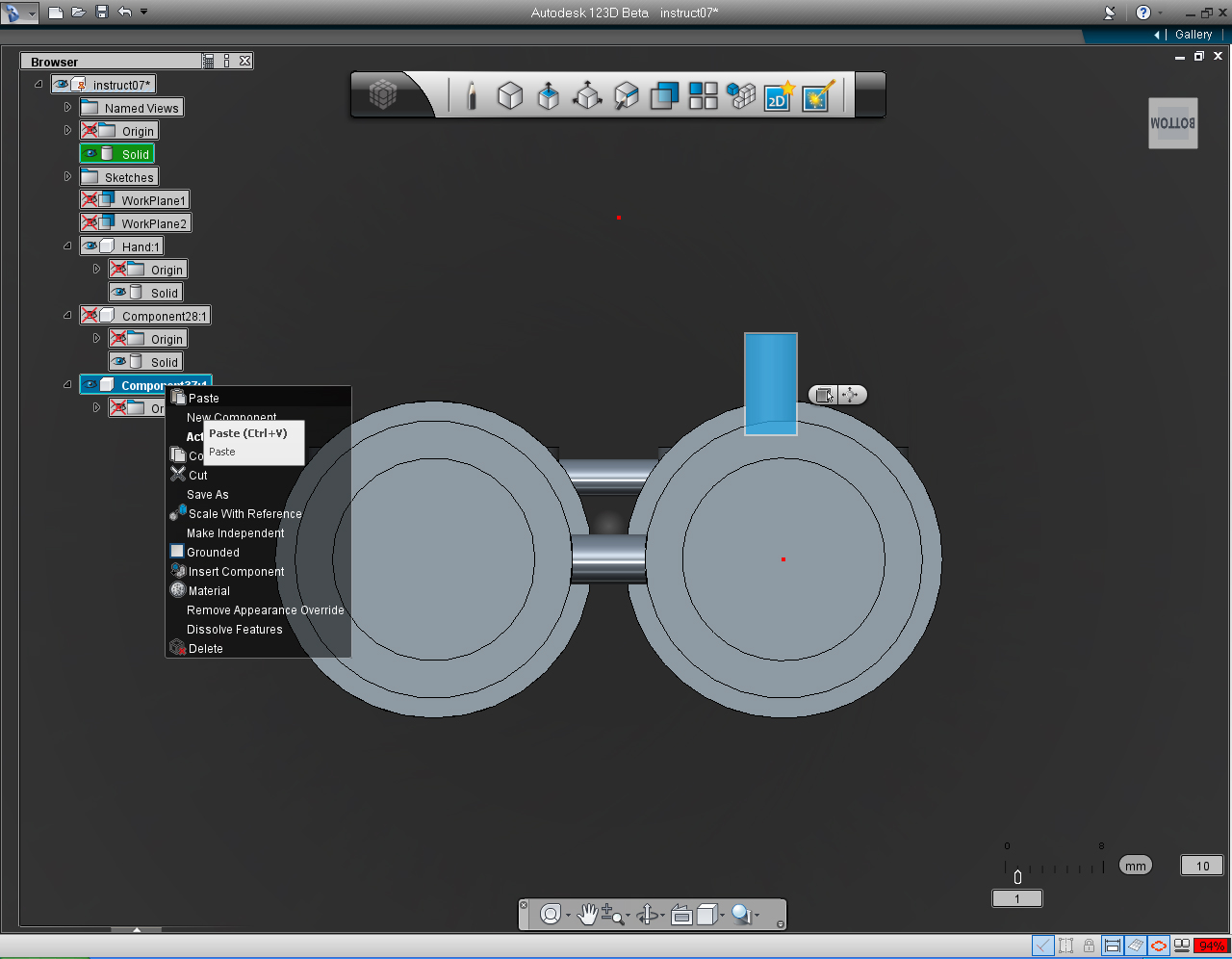
13. Right click at the Parent Item on the "Feature Browser" Menu. Select "New Component" from the list.
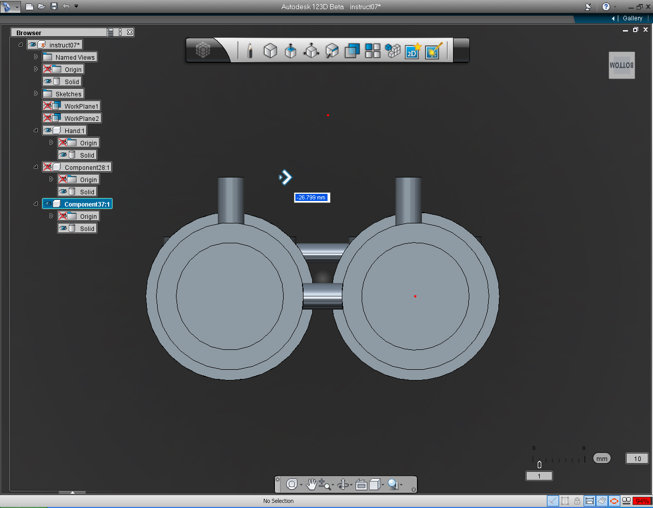
14. Right click on the newly created new component. Select "Paste" command on the list.
15. Drag the horizontal arrow toward the left approximately the middle of the shoulder on the left hand side.
16. Right click to bring up Marking Menu and select "OK" to commit command.
17. Change the view to sideway TOP.
18. Unhide Shoulders and Eyes Solid model.
19. Select the top extruded circle. Right click to bring up the "Marking Menu" and select "Solid Feature" -> Combine.
20. Hold down the Shift key, and select another extruded circle, Shoulders and Eyes, and Hands and Ears.
21. Clean up the empty component. And save the file!
22. Rotate the Solid around to admire your finished 3D print model!
Project Conclusion: 3D Printing File

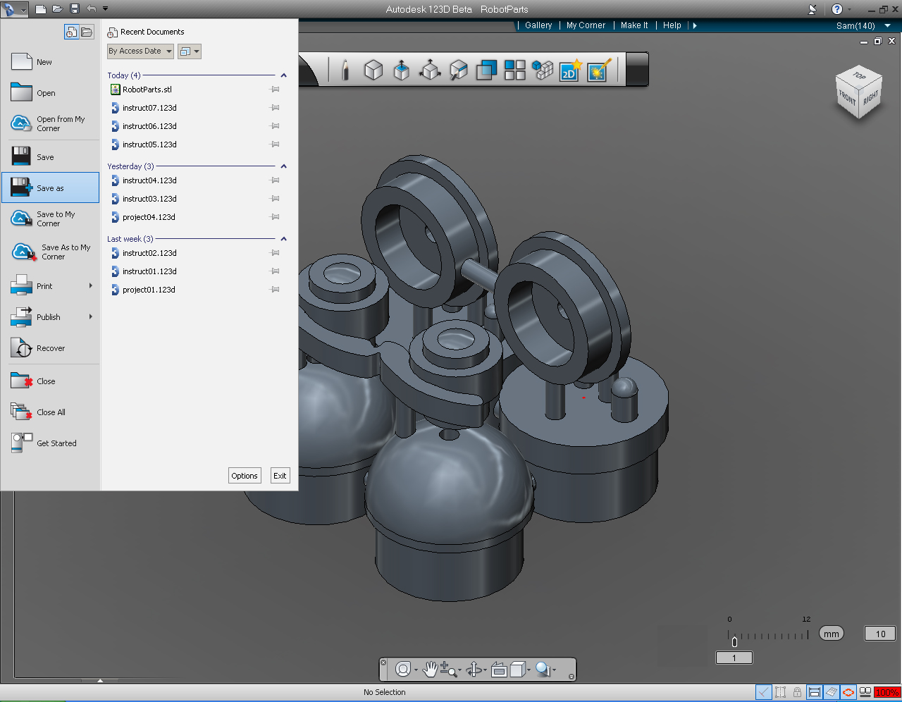
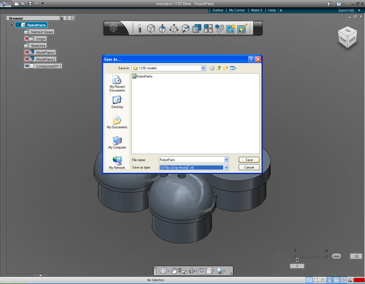
- Summary of what we are doing in this Step:
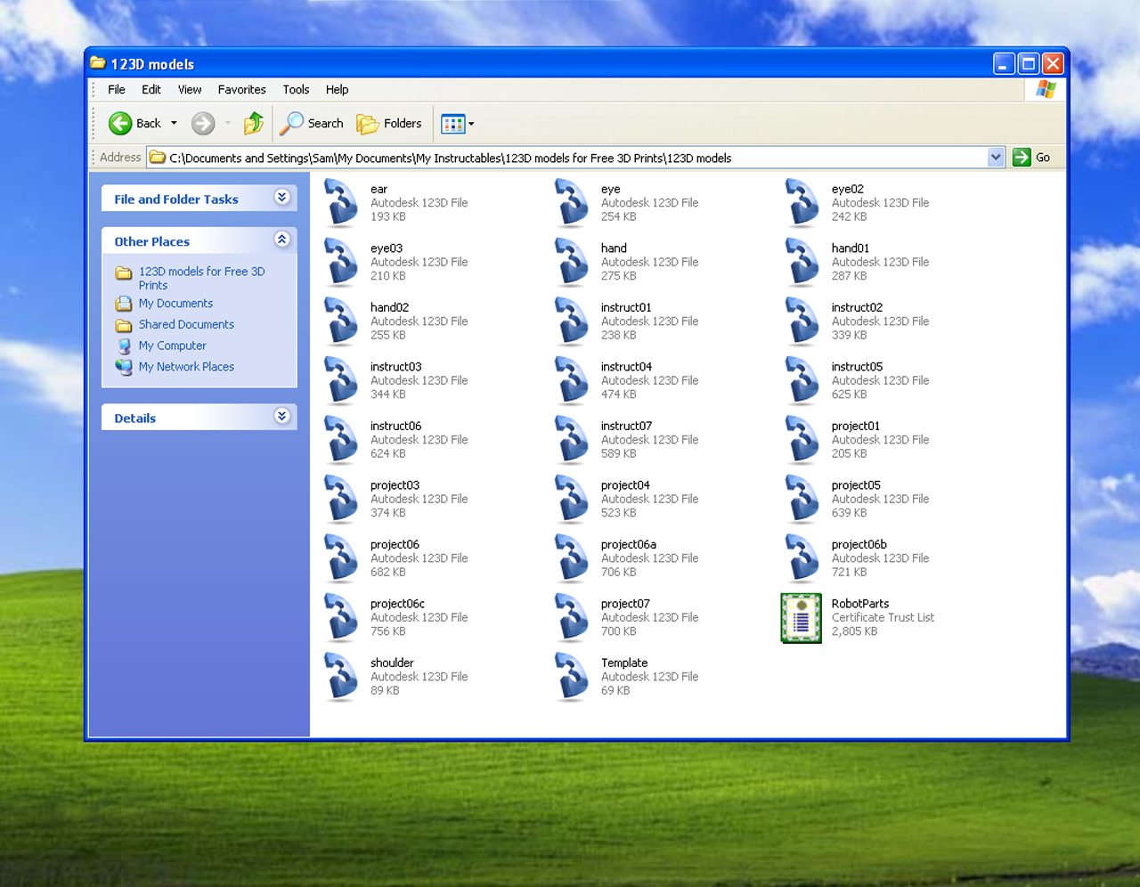
- Save the model to .stl file.
- Check the parts if it fits in 3x3x3" Cube.
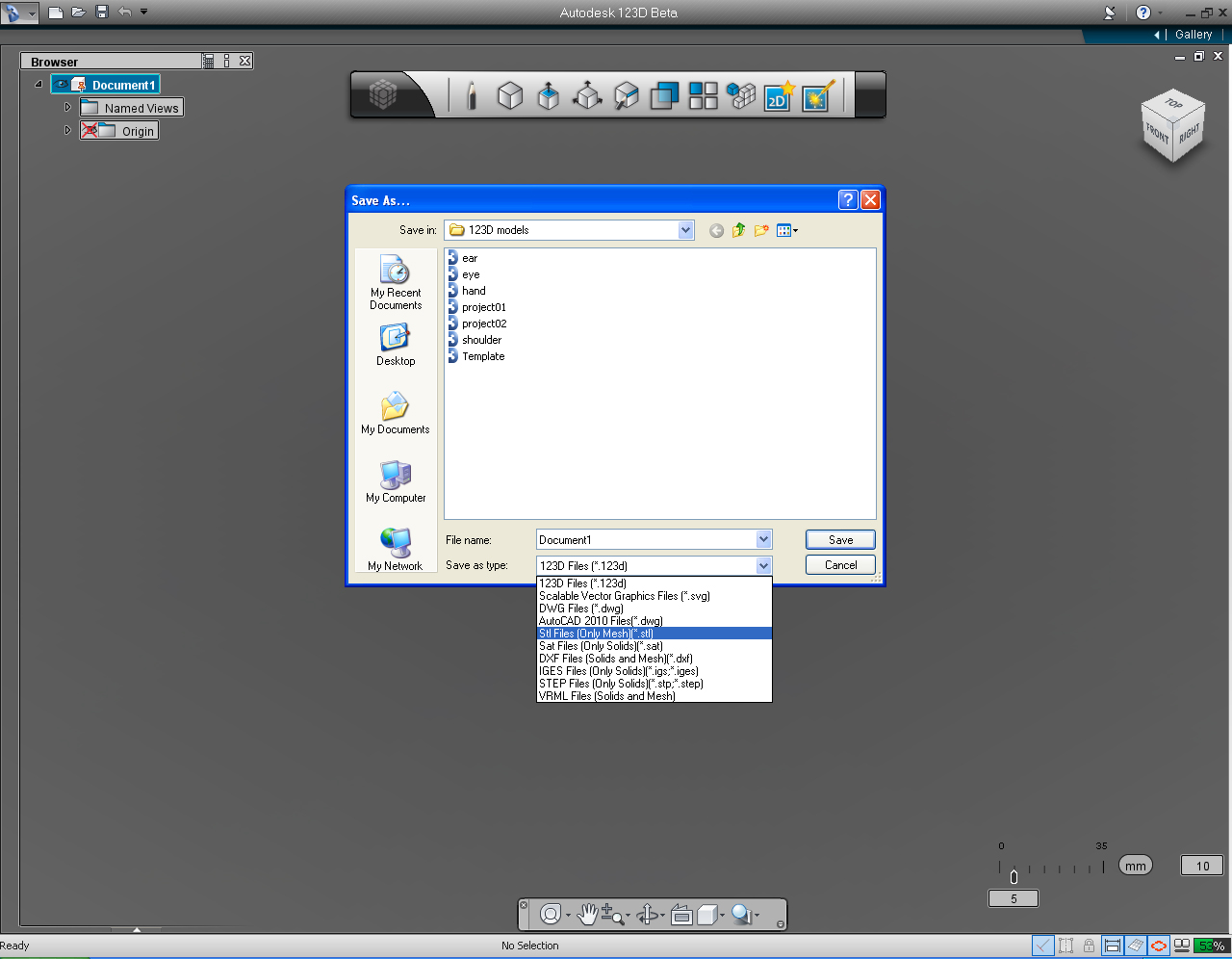
1. Select the "Application" Menu, and Select "Save as"
2. Save the 3D print model to .stl file format.
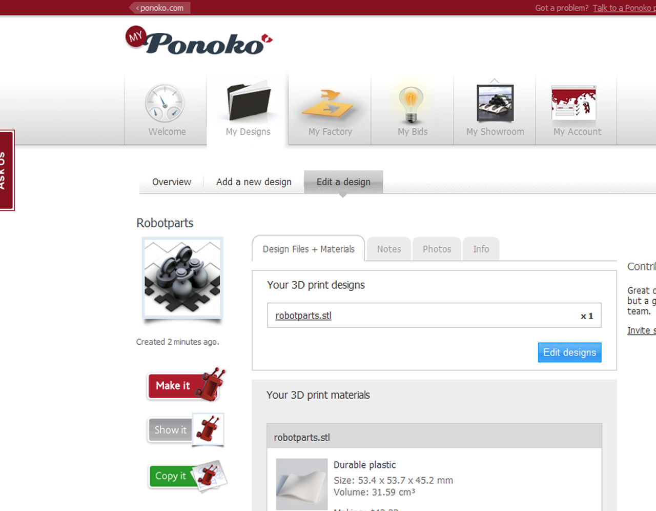
3. Submit the 3D print file to Ponoko (if you have an account, to see what would be the dimension of our 3D Print file.
( I got 53.4 x 53.7 x45.2 mm. Yeah, our 3D Print model is within 3x3x3" (76.2x76.2x76.2mm) allowance!)
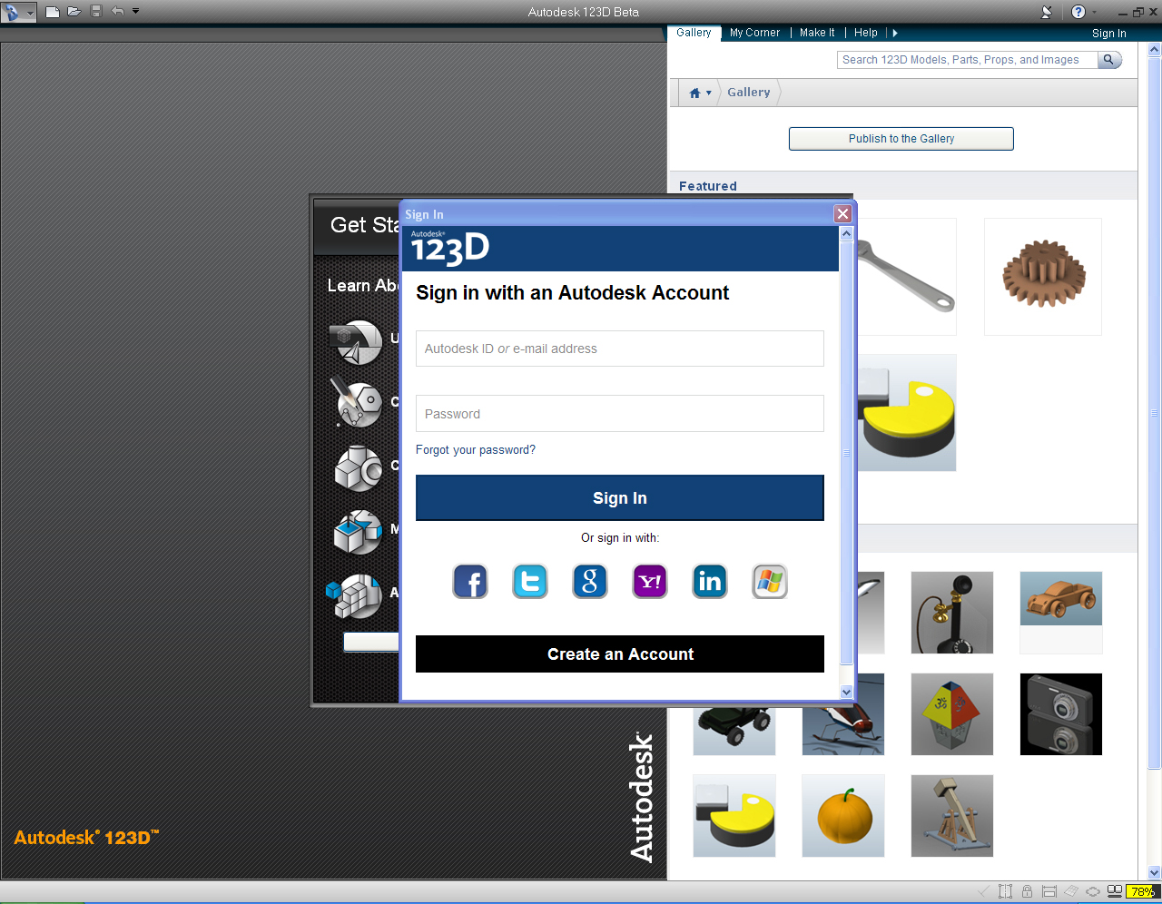
Note: If you are unable to save the file as .stl because there is no .stl option available!
That's because you have not sign in when you start 123D application. (See Step 3)
Following steps are necessary if you want to have it made for free at Instructables' "Free 3D Printing" Group.
- Write up a great instructable. ( A great (featured) instructable could make you a "Pro" member for a year and three month!)
- Post it!
- Add your instructable to "Free 3D Printing" Group
- Wait for to be made.
Otherwise, you could submit your .stl file to any 3D Print fabricators, i.e. Ponoko, Shapeway, or make it at TechShop if available in your area.
Resources
- Check out the Autodesk 123D Website
- Read the 123D Blog
- Visit the 123D Facebook page
- Watch the tutorial videos on youtube
- Participate in the 123D forums
Looking forward to seeing your 3D Print appears on Instructables!
Resources
Autodesk 123D - Intro to Sketches Video Series:
First Sketch
Precise Sketching
Multiple Sketches Part 1
Multiple Sketches Part 2
Finalize your design
123D Tips Video Series by 123d:
(123D beta 4 Tutorials)
Tip#1: User Interface Tour
Tip#2: Modeling Starting from a Sketch
Tip#3: Refining Shapes
Tip#4: Multicomponent Design - Design Intent
Tip#5: Multicomponent Design - Components
Tip#6: Changing Scale of a Component
Tip#7: Copying Objects
Tip#8: Copying with Pattern Tools
Tip#9: Using the Mirror Function to Copy Objects
Tip#10: Design with Dimensions
Tip#11: Combining Bodies-Booleans
What's New in 123D Beta 9
Fabricators Design Rules
Ponoko's Design Rules
- Ponoko provided a page regarding their 3D Design Rules
Shapeway's Design Rules
- There are a lot of info. on tutorials page regarding the design rules.