123D- Beginners First PCB for Arduino SERVO/SENOR BOARD
by treyes4 in Circuits > Arduino
6360 Views, 42 Favorites, 0 Comments
123D- Beginners First PCB for Arduino SERVO/SENOR BOARD
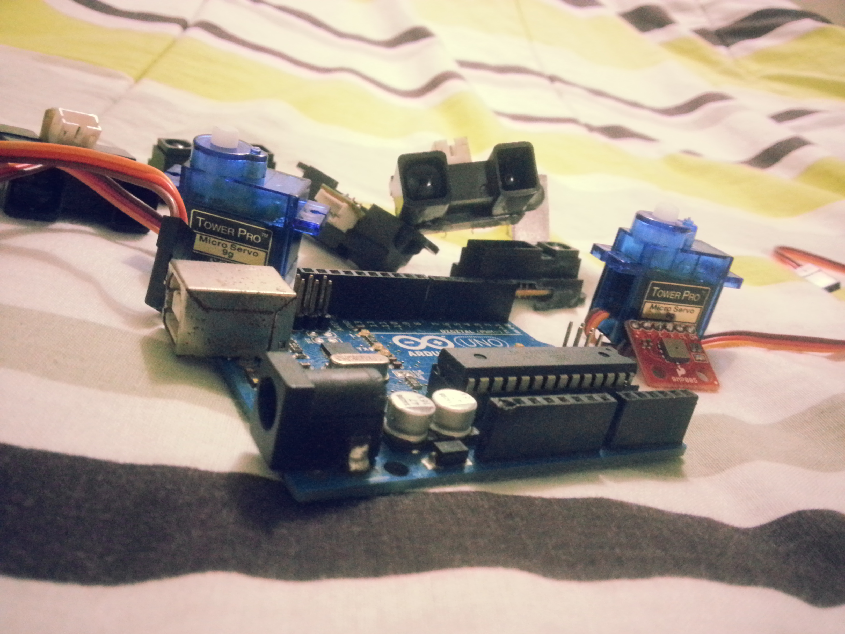
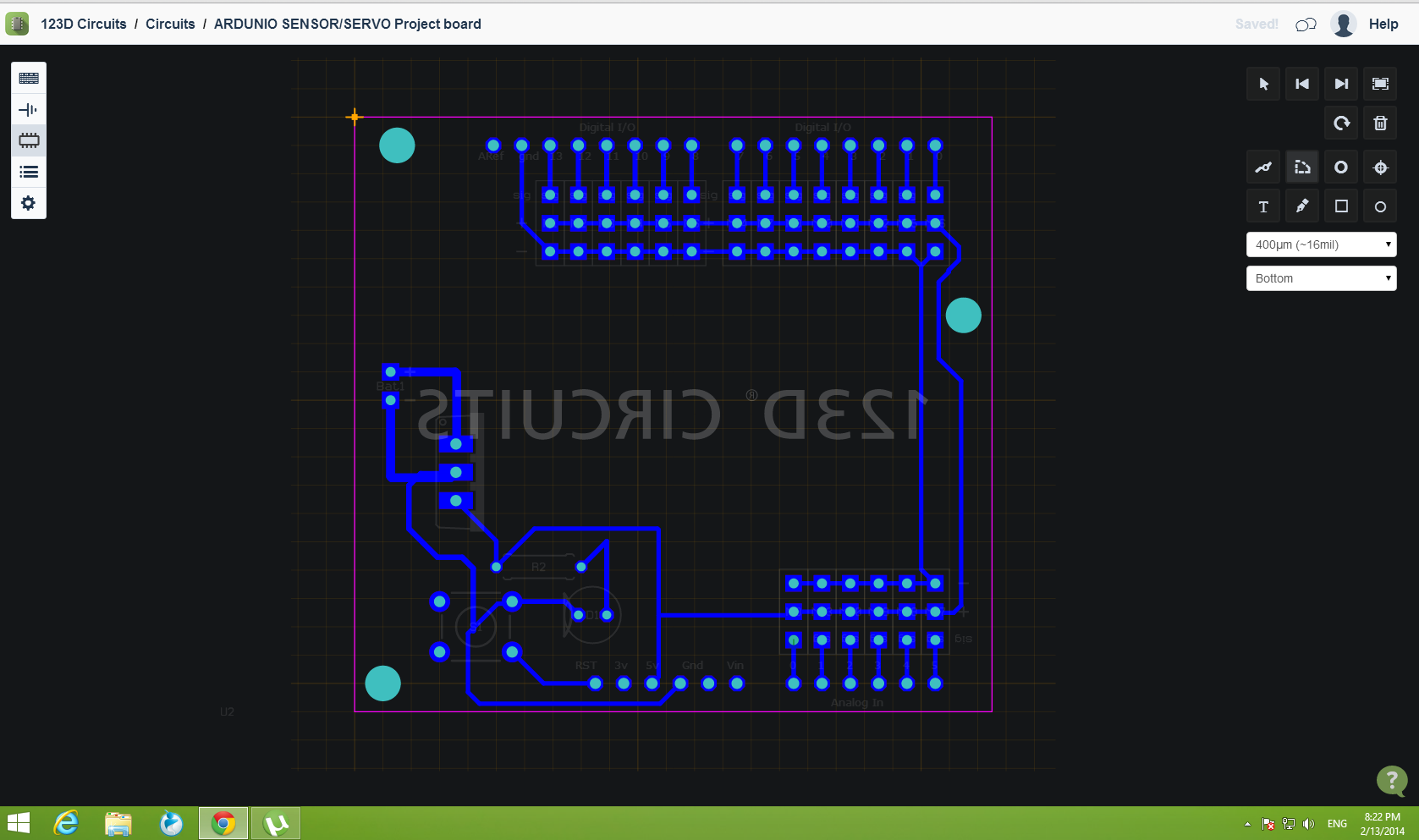
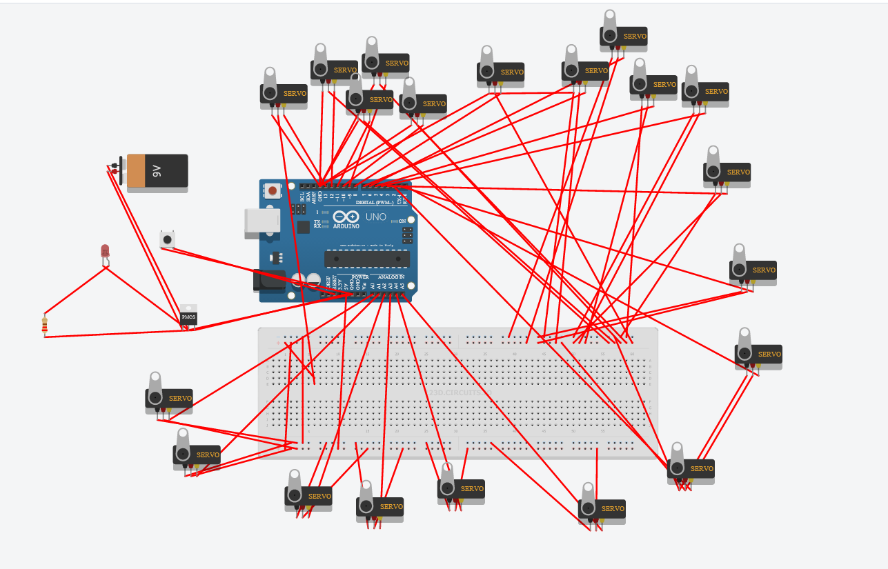
Today I will be using 123D circuits for the first time and as a developing program I tried it for myself and here is a simple project wherein you can practice your pcb designing skills in a different environment. After guiding you through the ibles I will also teach you guys how to make the PCB but I might release it this Saturday Feb 15, 2014.
(BEFORE YOU START MAKING YOUR OWN DESIGN BE SURE THAT YOU HAVE NOTHING ELSE TO DO BUT MESS AROUND WITH 123D Circuits THE WHOLE DAY)
Components needed after designing
- Pre-synthesized
- Pin Headers LONG FEMALE or what we call it "SHE-MALE" yeah......
- LM7805 VOLTAGE REGULATOR
- 220 ohm REsistor
- 5mm LED your color~
- tact switch
- 60 male pin headers
- PCB DEVELOPER
That's all and you have a sensor board for your arduino ~
Dl the pdf file If you really dont like the 123D and you just want to go on with the pcb
Downloads
Getting Started~
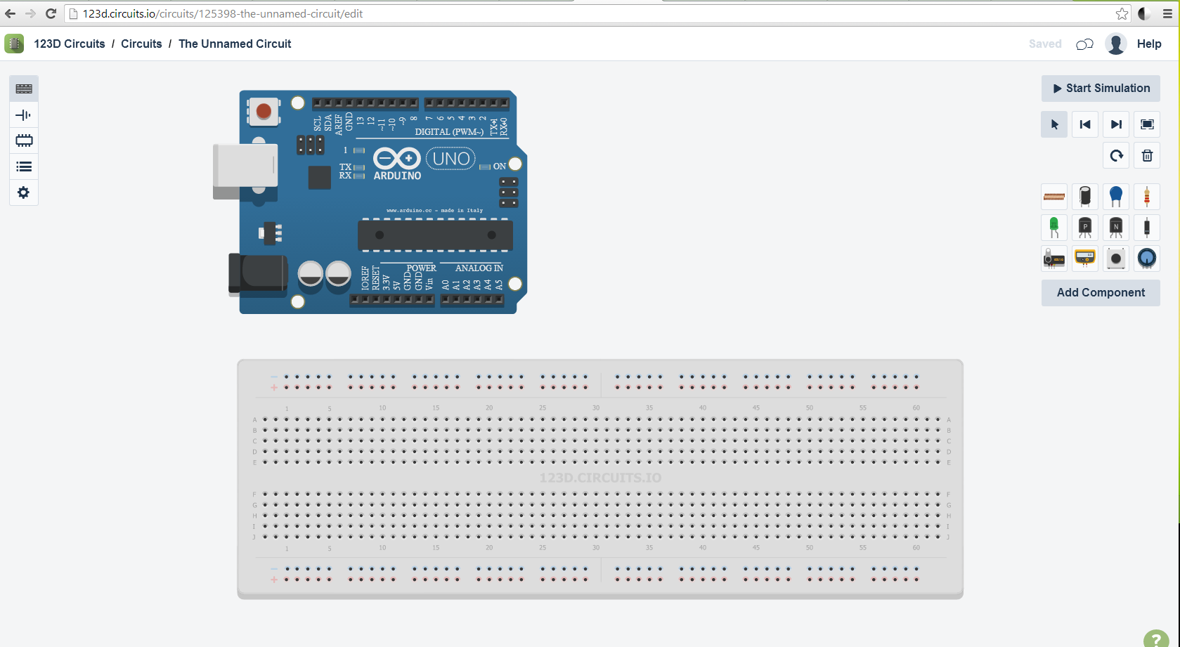
Sign UP for 123D circuits and lets get started
Click on New bread board and you will immediately go to an editor and inside it is an arduino and a bread board
Look at the upper right and you will see a tab with components click on "add component" and it will open up the components you have.
Look around it and be resourceful in how you will manipulate the pins on the pcb in the following steps
in short just mess around with the whole application!~ XD
I'll get to the serious part~
Knowing How the Application Works
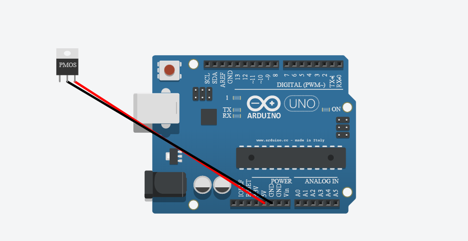
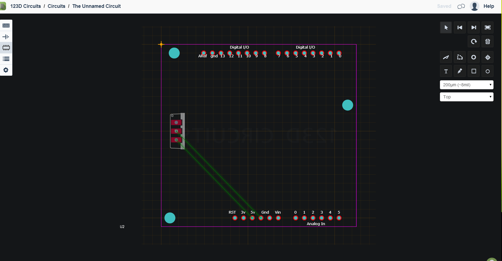
If you observe the whole project revolves around the main bread board and as you connect and add components other components and symbols add up to your schematic and pcb tab.
For my situation I just messed with the bread board and PCB since I find the schematic part kinda inconvenient
and it adds up to the work I mean its faster to just draw the schematic right.
Soooo..... Here is the plan we put components on the bread board and see what happens on the pcb tab~
figure out how to move the components first and lets go back to the bread board. Start with a simple 5v regulator circuit using a 7805 transistor or just a TO220 transistor found inside the components. From left to the right is *input*ground*5v OUT its that simple and now just connect your ground to the ground pin of the Arduino and 5v out to the 5v pin of the arduino. Now lets go to the bread board. Lets start arranging the components.
Connecting the Lines in the Pcb Tab
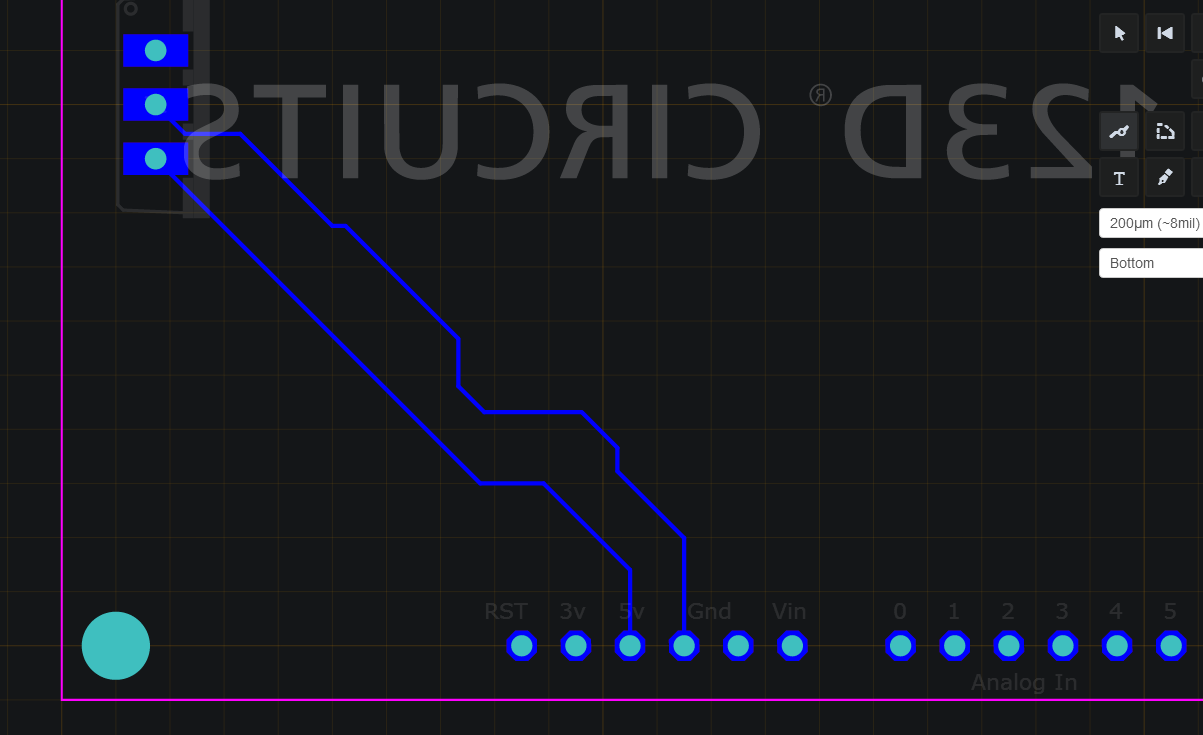
Now you see green lines on the pcb those are going to be the copper so now hover on the buttons on the upper right and read the names of each button click on trace tool and on that corner you see a "Top" now we set it to bottom meaning we are switching from a top view to the bottom view wherein we can connect or pcb's the easy and standard way. Now again click on the trace tool and left click on the pin of the component from then on you will see a blue line next "from green to blue" Now that its turned blue click anywhere you like and understand how it works.
Adding the Sensor/servo Pins
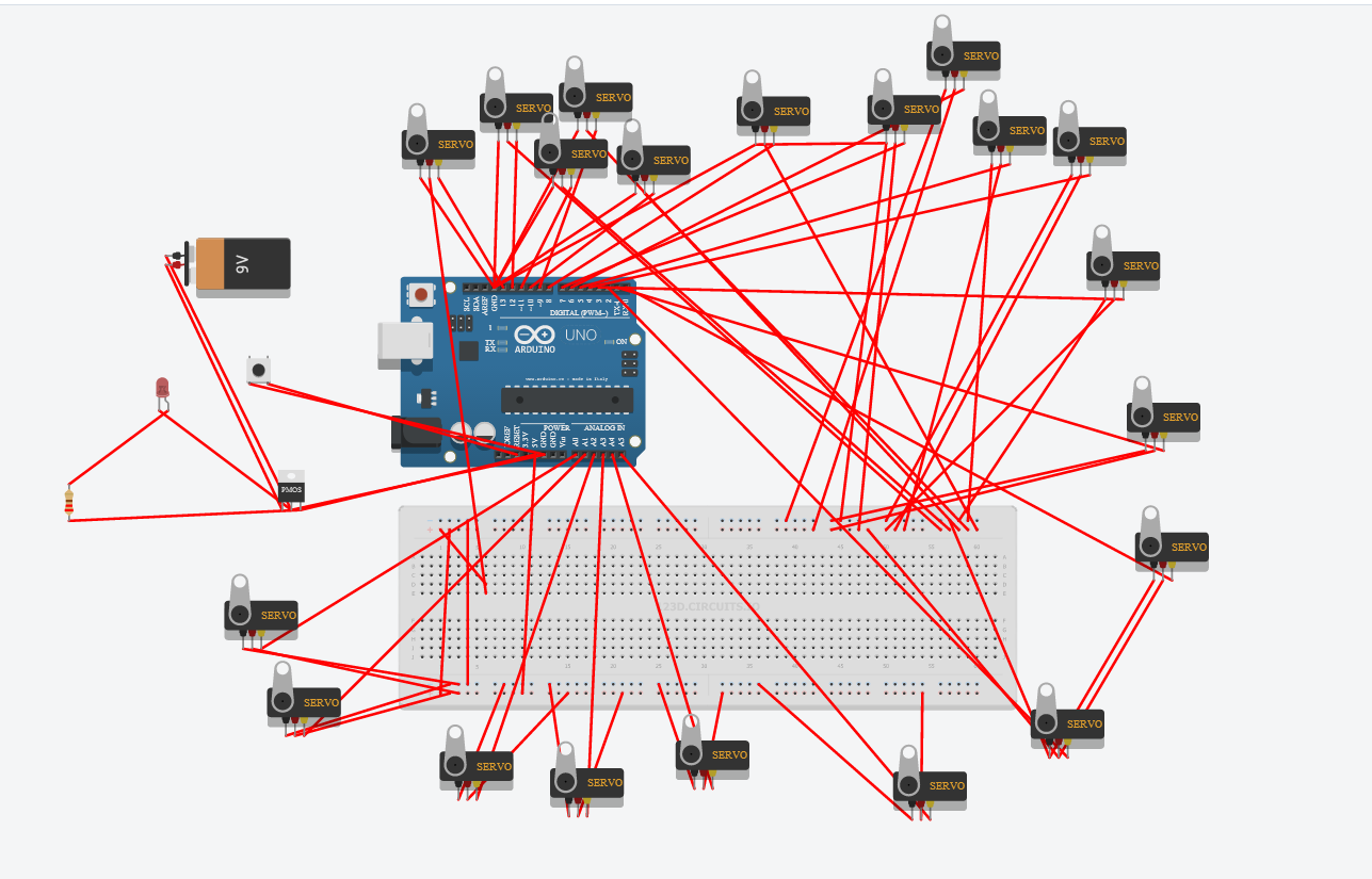
This is going to be a tricky one since you will be adding 20 servos meaning a lot of connections on the breadboard = to frustration and confusion sometimes the key here is organizing and working in a quite place.
Or if you can keep up with your tracing just concentrate on the pcb tab and not really on the breadboard like me hehehehe. your bread board should look like this a messy and confusing bread board well dont expect much from a highschool student like me and a new application "123D circuits"
At this point to all non 123D circuit users you just realized that using this inefficient but looking at it its a good way for illustrating simple circuits well that was the real intention at first right?
Anyways If you find this application boring plss respect the program because it can still be useful since not every computer has one of those EagleCad or Cadsoft programs.
Adding Components and Tracing on the Pcb
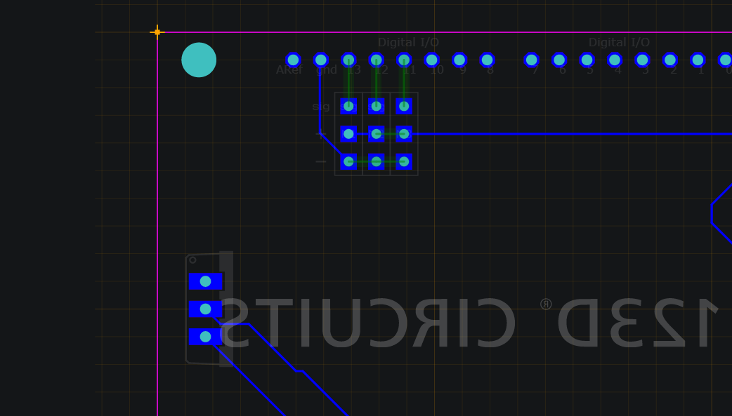
Go to the breadboard again and add the servos yellow wire goes to each individual pin D13 to RX 0 and A5 to A0
and just connect the all the 5V and all the ground after that just keep on tracing the connection one by one
If you Can do that just keep on doing the same thing until you reach the A0 the 20th servo pin on the project
(DOWNLOAD THE PDF FILE IF YOU HAD enough of 123D circuits)
this may also serve as a guide if you want to continue the project in 123D
Downloads
My Work on 123D and Cadsoft
Downloads
PCB FABRICATION
Coming this Saturday~