🤓 3d Printed Rainbow Specs 🌈
by Lina Maria in Workshop > 3D Printing
1272 Views, 16 Favorites, 0 Comments
🤓 3d Printed Rainbow Specs 🌈
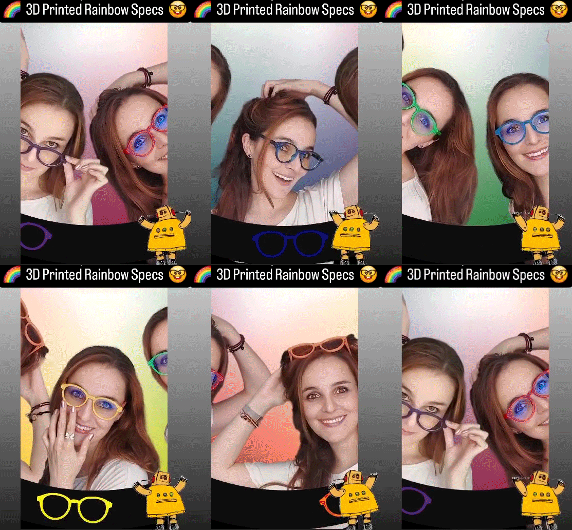
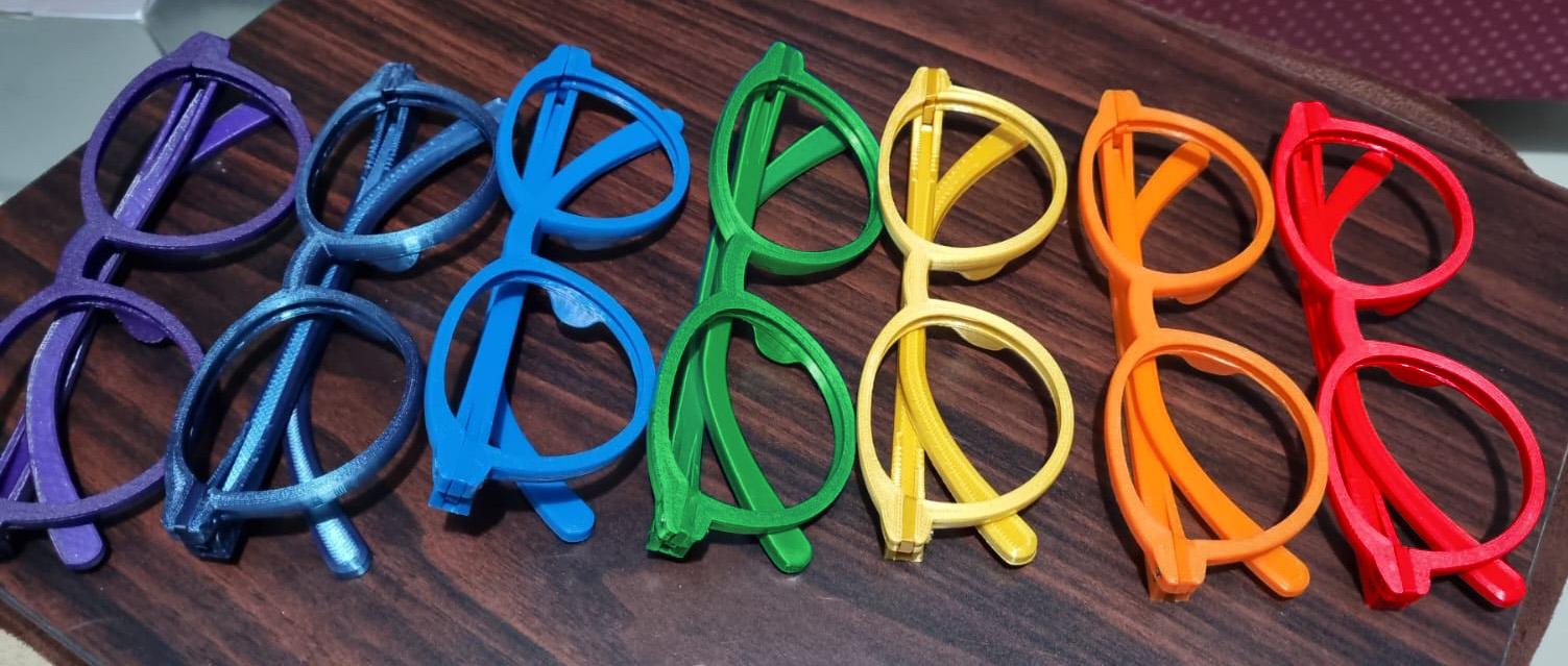
I've been using these glasses since January 2024. Initially, I had very few colors printed before deciding to make this instructable, but doing it seemed a good reason for having more colors. They quickly became my favorite, and concerned about their impact on my vision, I visited an optometrist. He liked them so much he asked if I could sell him some! He also showed me some tricks to improve plastic glasses. When it was time to check my prescription, new lenses were made directly for the printed frames. You can find more about this story in Step 1.
Instructable Contents:
- Step 1: .................Why were these glasses created?
- Step 2: .................Frame shape and measurements
- Steps 3 - 11: ........3D modeling Version 1
- Steps 12 - 14: ......3D modeling details for Version 2
- Steps 15 - 18: ......3D modeling of the legs
- Step 19: ...............About the STL files
- Step 20: ...............3D printing
- Steps 21 - 27: ......Assembly
- Steps 28 - 30: ......Improvements and customization
Supplies
Before 3D printing:
- Guide glasses frame (for size and shape)
- Scanner
- Illustrator
- 3D modeling software (I used Rhino and Autodesk Inventor)
- 3D printer
- 3D printing filament in the desired color
After 3D printing:
- M2x6mm and M2x8mm screws (two of each and their respective nuts)
- If you are using PLA for printing, then you can use methylene chloride to glue it.
- Eyeglass lenses
- Heat gun or hairdryer
Why Were These Glasses Created?
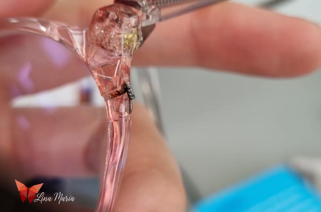
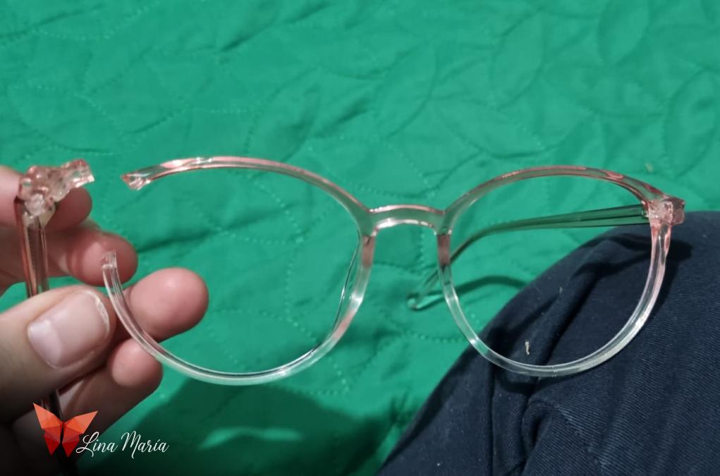
The day before an international trip in January, the frame of my glasses broke. Despite my attempts to fix them with wire, I couldn't get them to work properly. I was traveling alone, and my distance vision is very poor, so this was a serious problem that needed a quick solution. I went to the optician to find a replacement frame, but my search was in vain. There were no frames that fit my lenses, and they offered to have one ready in a week, which didn't work with my plans.
So, I decided to 3D model a frame and go with that, hoping to buy new glasses in the other country or when I returned home. I spent the afternoon modeling and the night printing. To my surprise, I fell in love with the new frame and the ability to print them however I wanted, in any color I desired, change details in the 3D model and even experiment with glow-in-the-dark filaments.
Months have passed, and these have become my favorite glasses. When I went to get my prescription checked and new lenses made, I submitted this frame for the new lenses. Interestingly, most people who see them and hear their story ask me how much I would charge to make a pair for them.
Frame Shape and Measurements
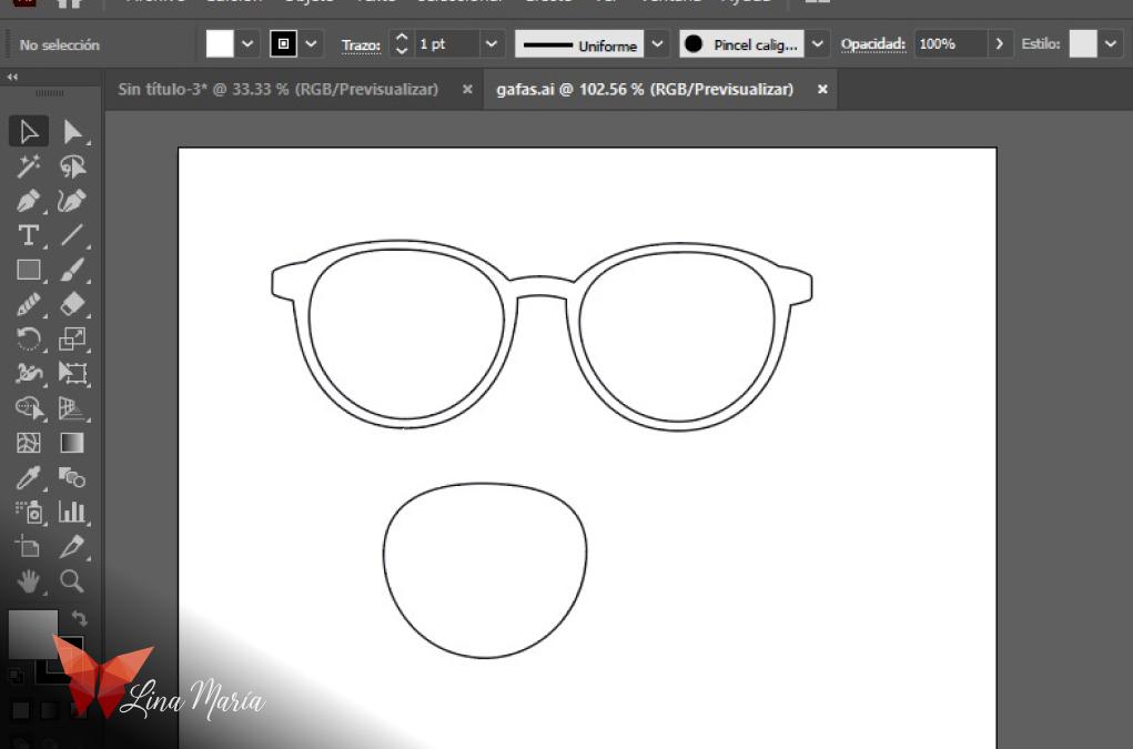
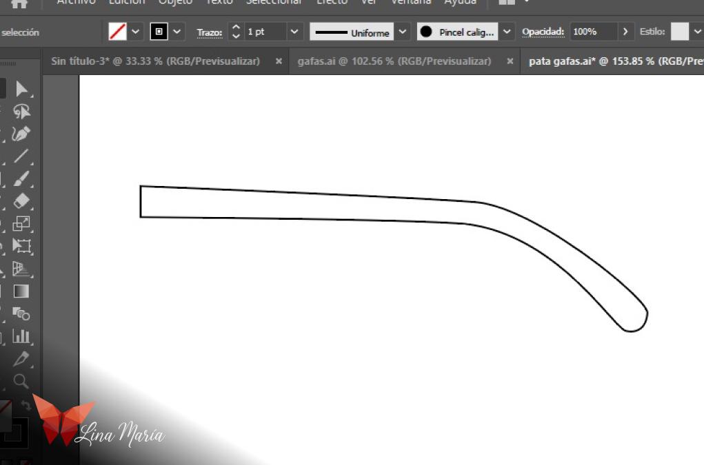
I used the broken glasses frame to create my new glasses, ensuring the lenses would fit. I placed the frame on paper and traced its outline as accurately as possible, like a stencil. I didn't measure the dimensions but focused on making the outline of both the front and the arms very precise. I knew that scanning it with a real scanner (not a cellphone) would keep it to scale.
Next, I traced these drawings in Illustrator and imported them into Rhino, where I performed a simple extrusion and saved it as an IGES file to use in Autodesk Inventor.
3D Modeling Version 1
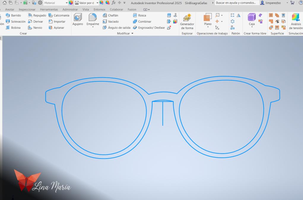
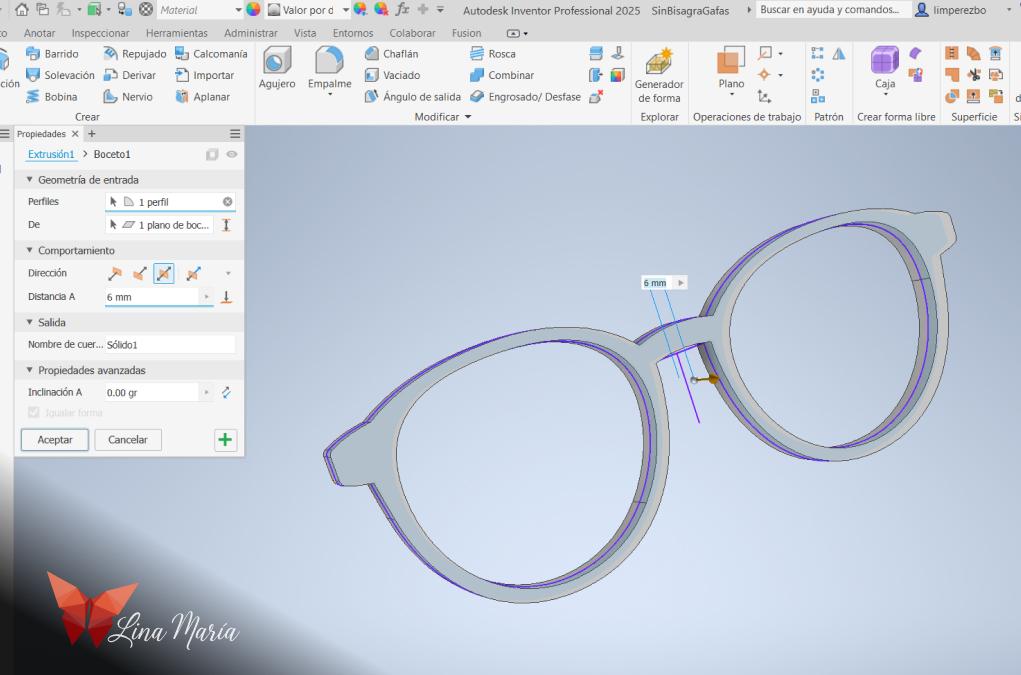
I opened the file in Inventor (starting with the lens frame) and began by ensuring it had a width suitable for creating the channel to hold the lenses. To achieve this, I extruded it again to confirm the measurement.
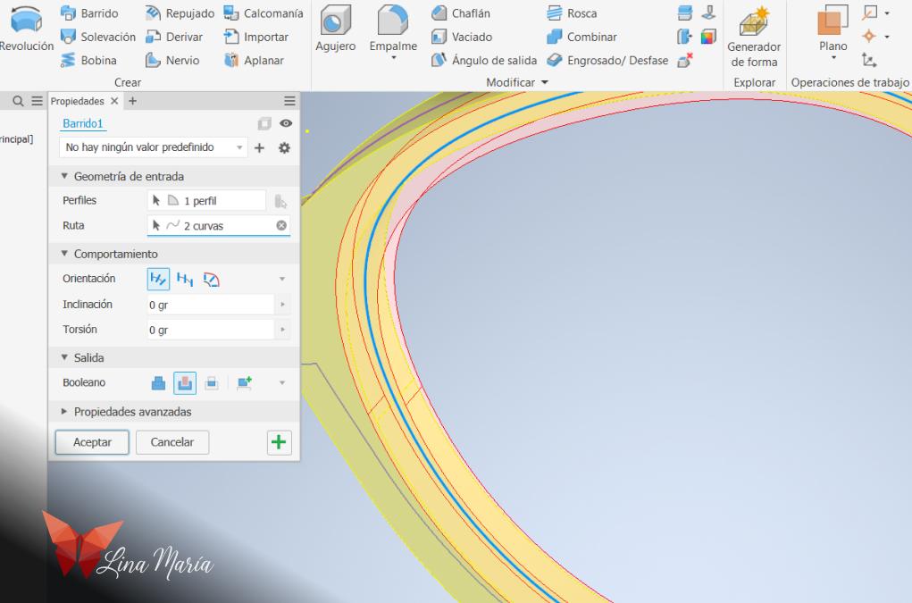
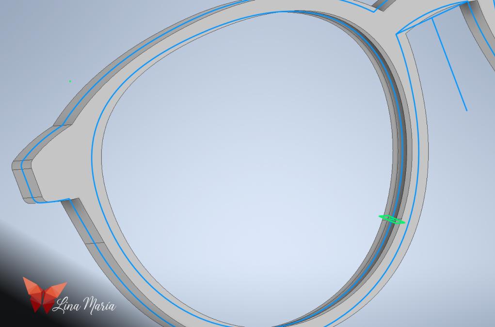
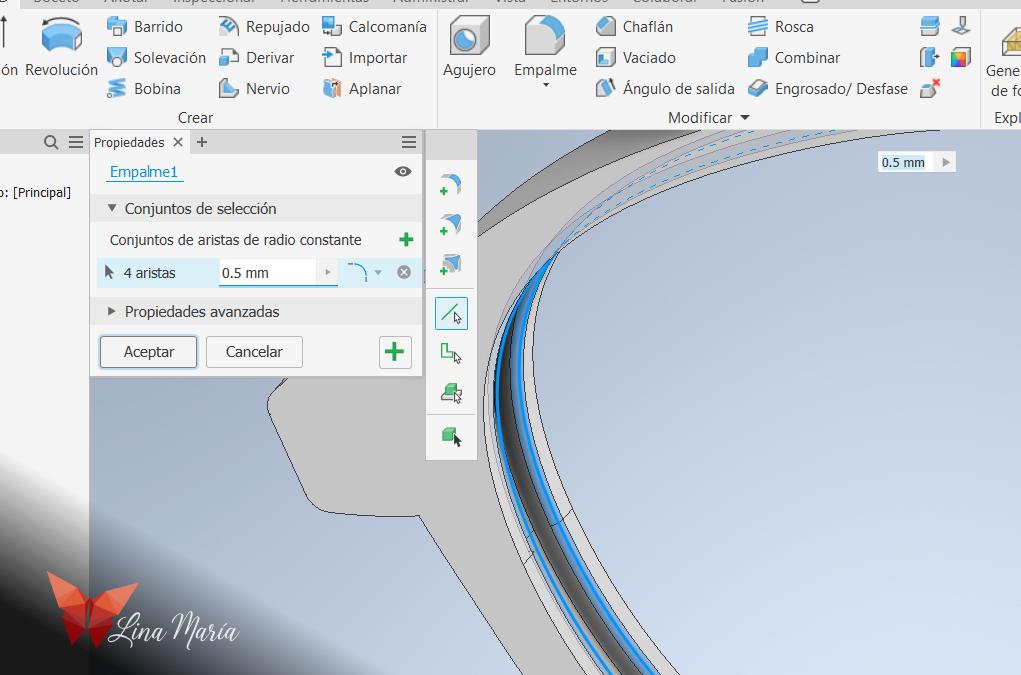
In the middle of the frame's width, I traced the edges and drew a circle on a perpendicular plane. Then, I used the sweep function to create the channel or space where the lenses would fit.
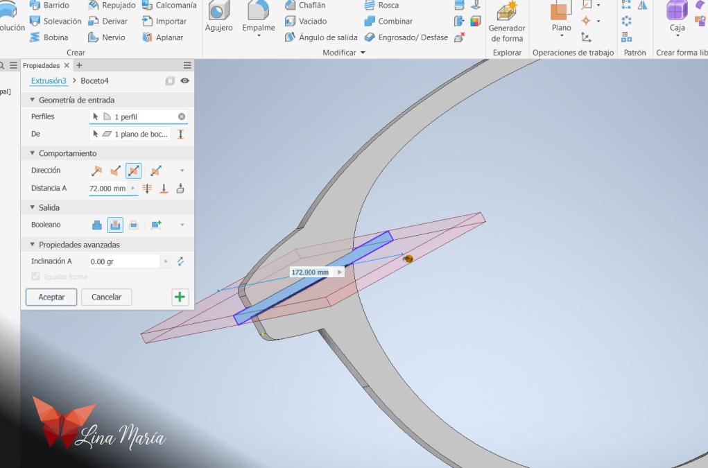
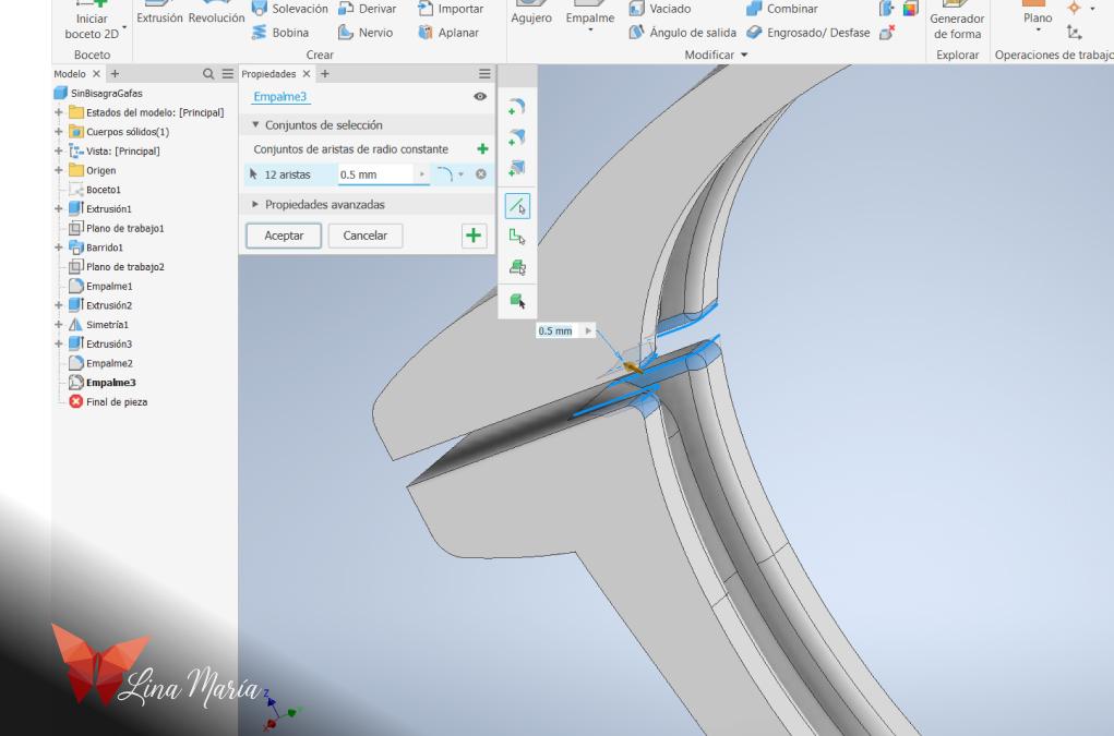
Next, I cut a small section in the corner so that when printed, it would remain open, allowing the lenses to be easily inserted and removed.
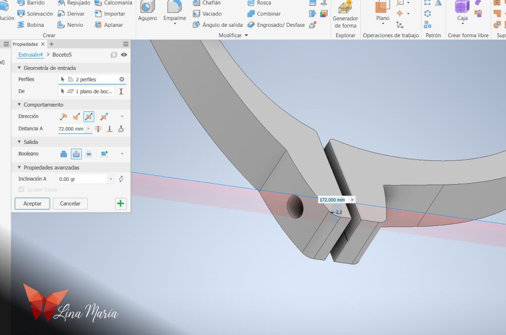
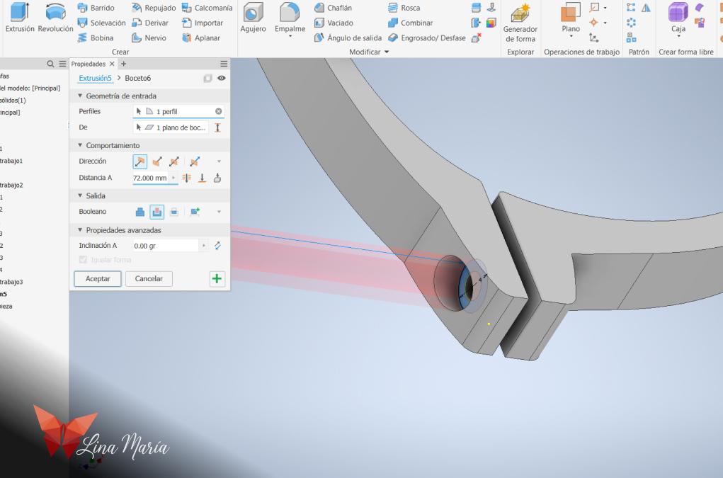
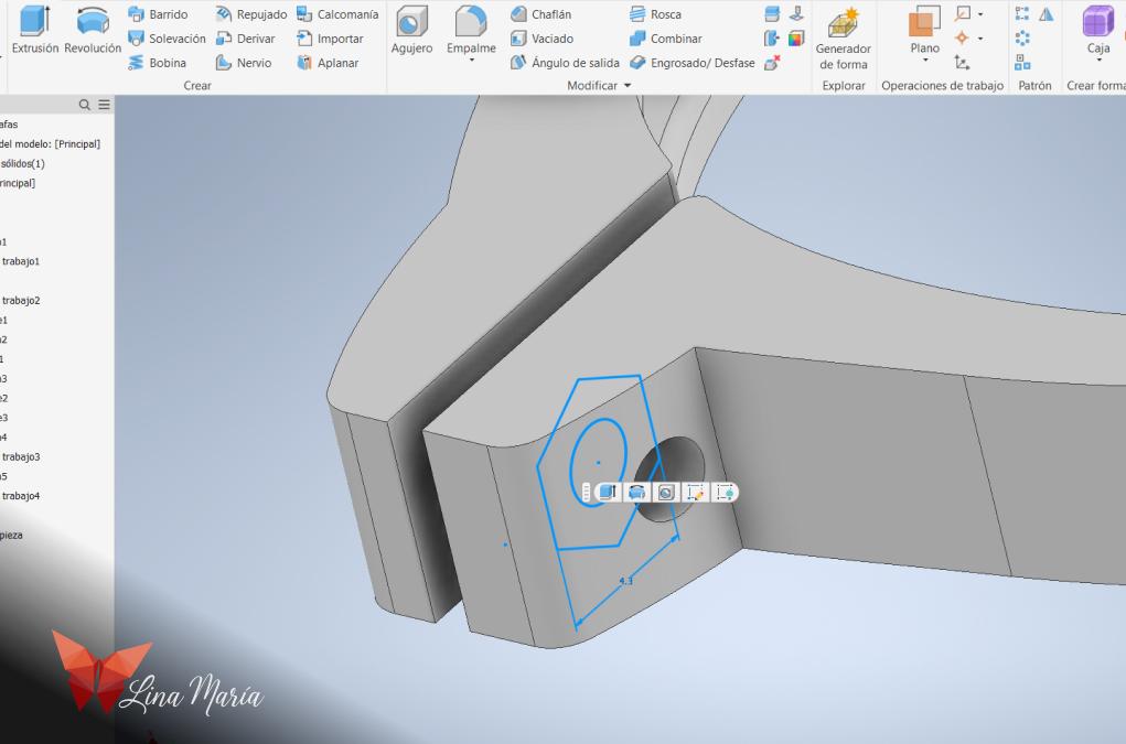
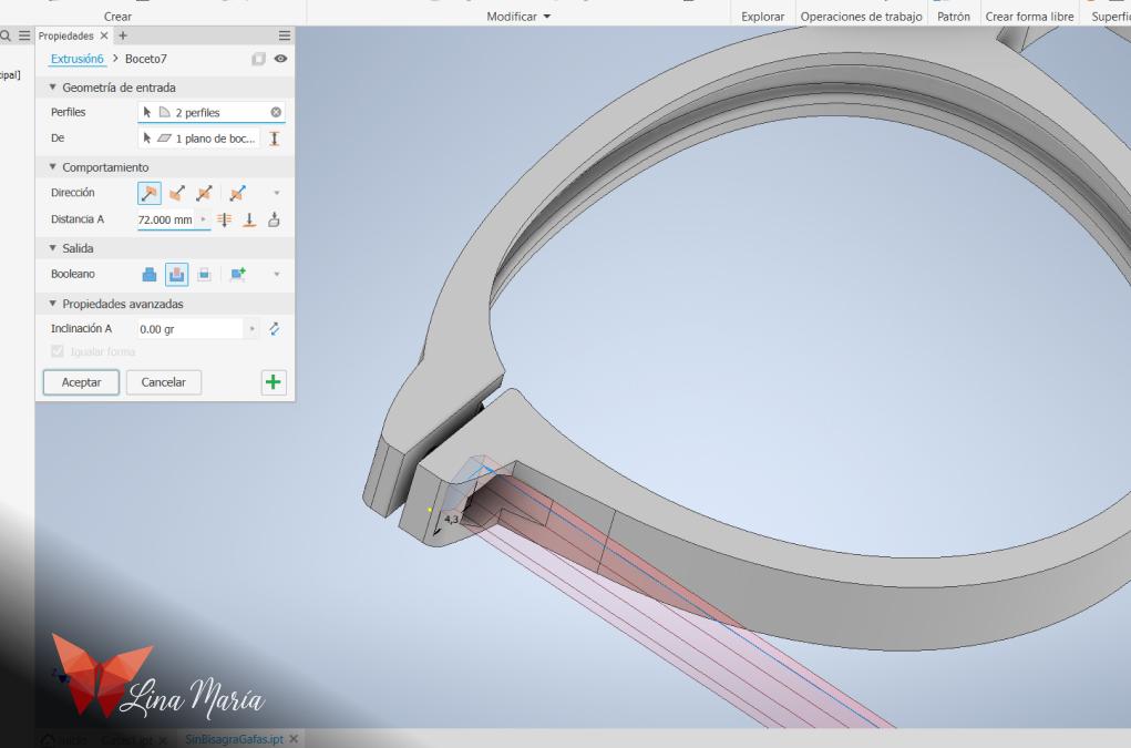
Then, I created the spaces for the screws and nuts.
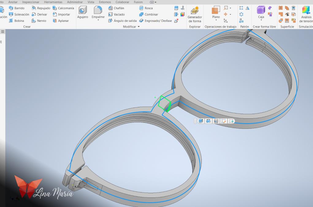
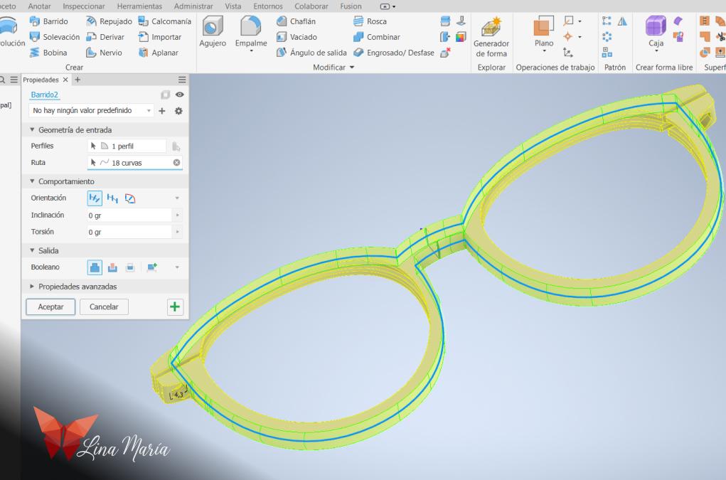
Using the same sweep function, I created a curve around the frame to make it a bit more aesthetically pleasing.
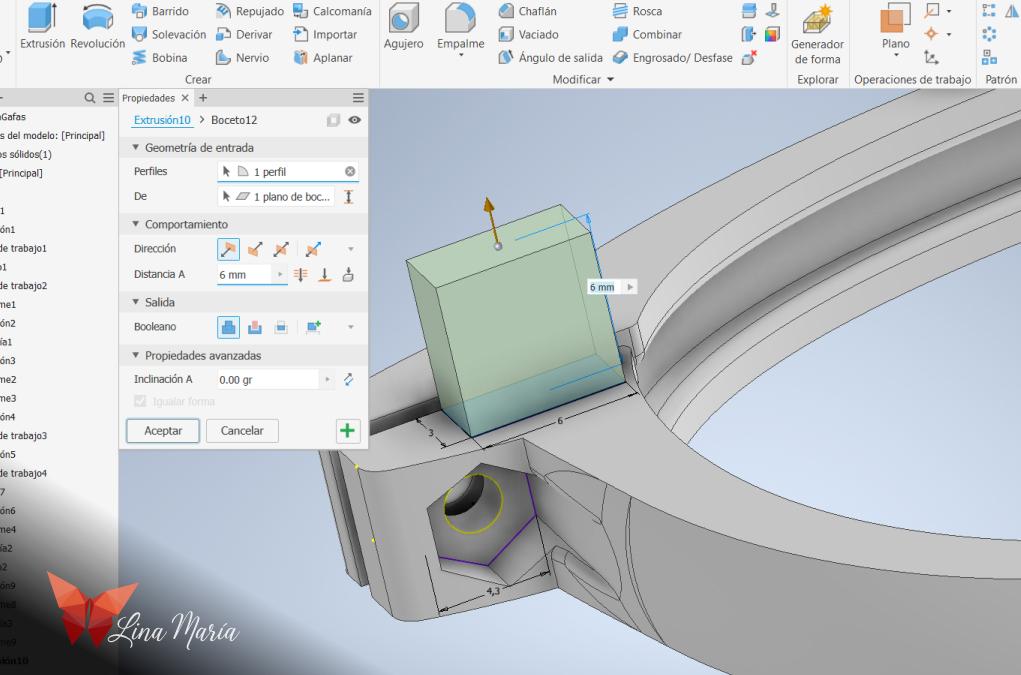
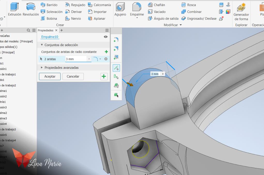
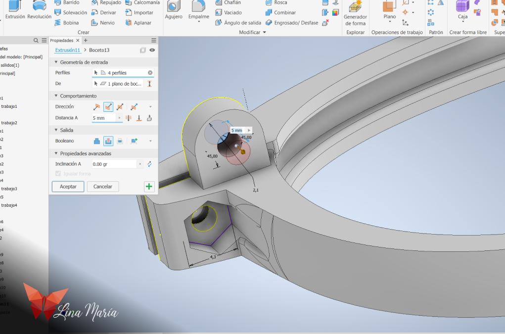
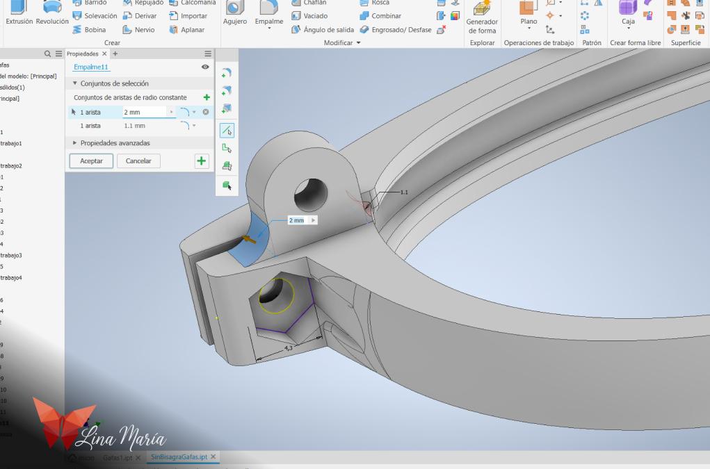
I created the hinge part to which the arms would be attached.
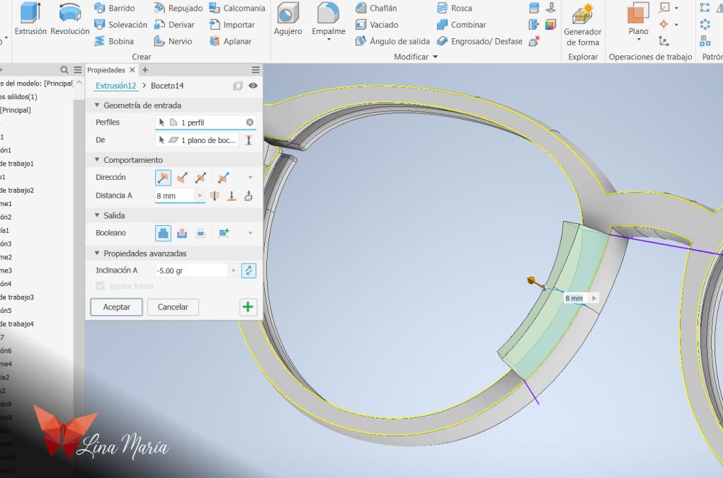
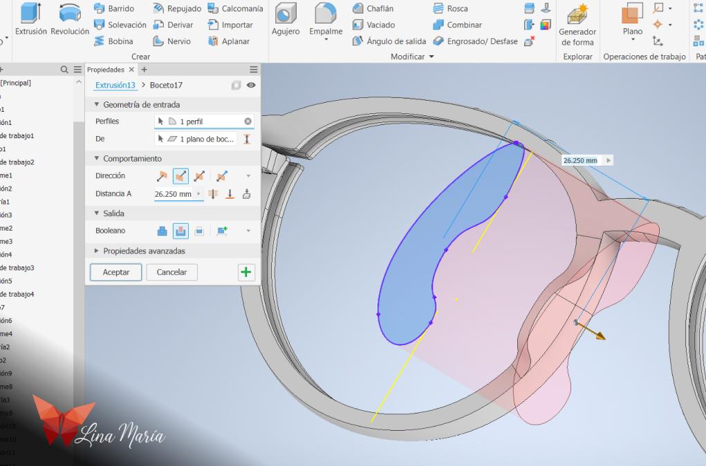
And the curves that provide support on the nose.
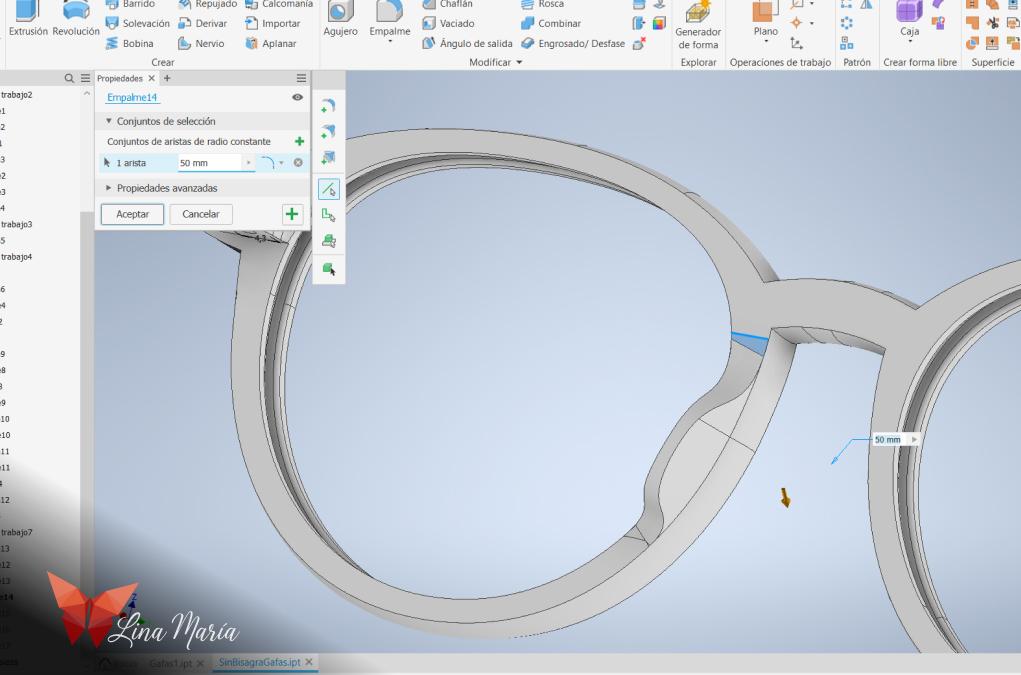
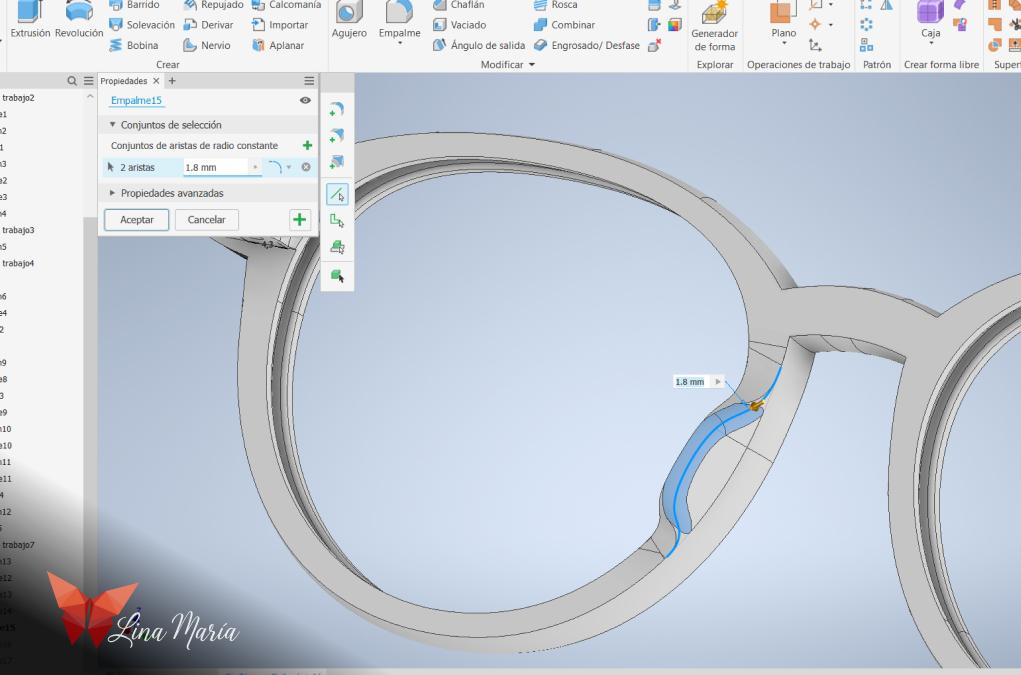
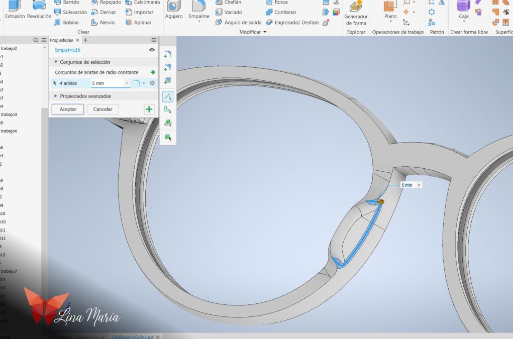
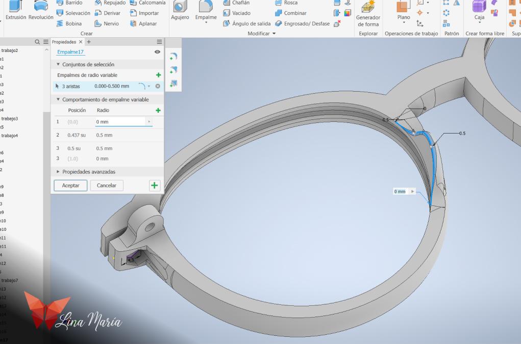
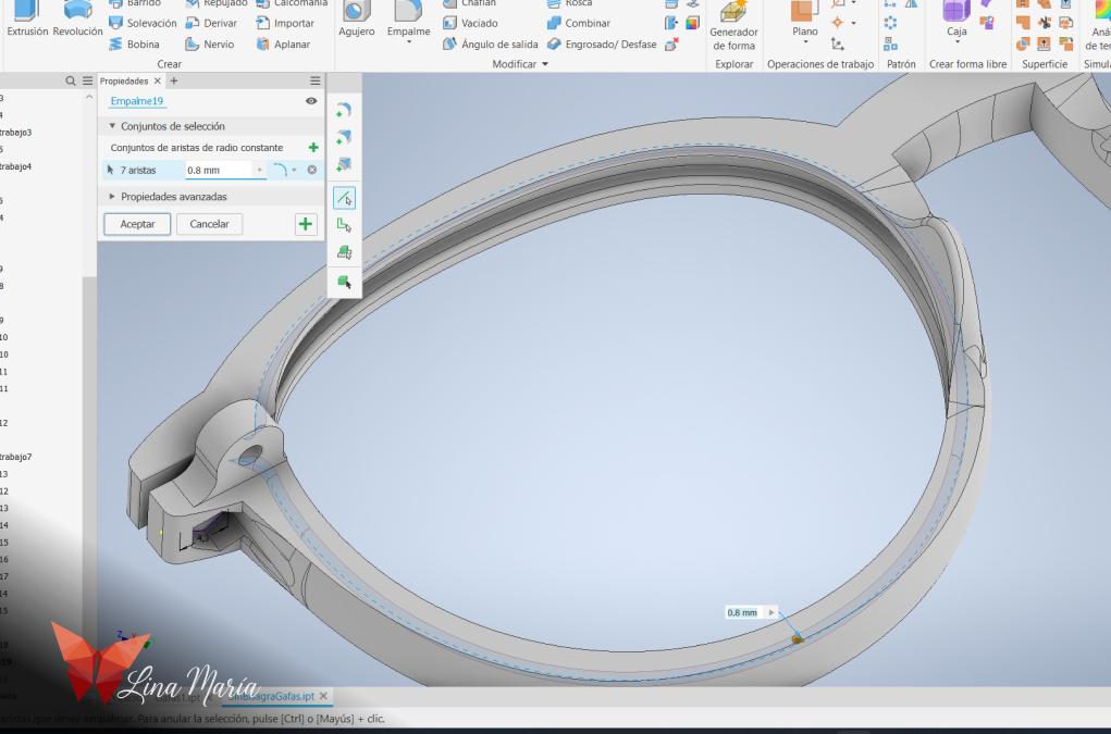
Then, I curved this section as much as possible to make it as comfortable as possible.
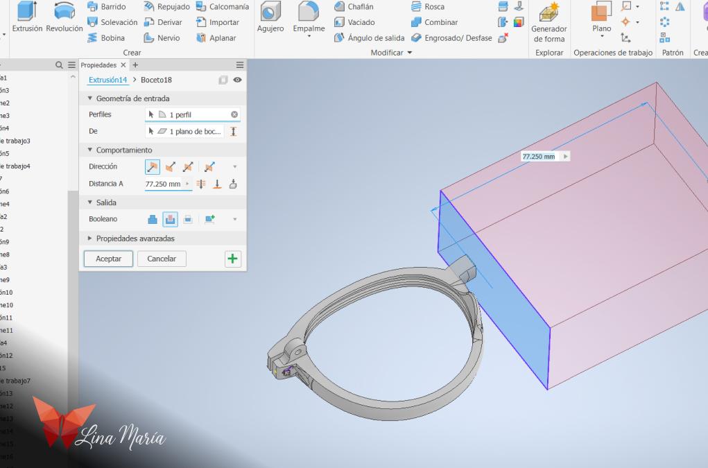
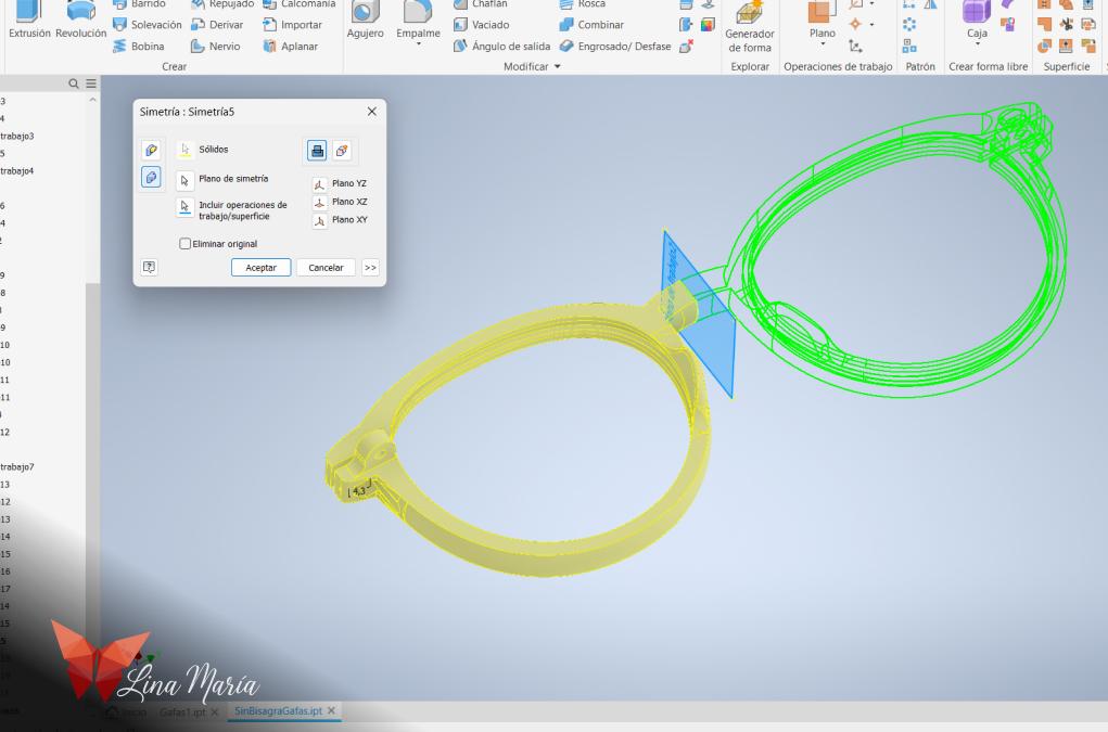
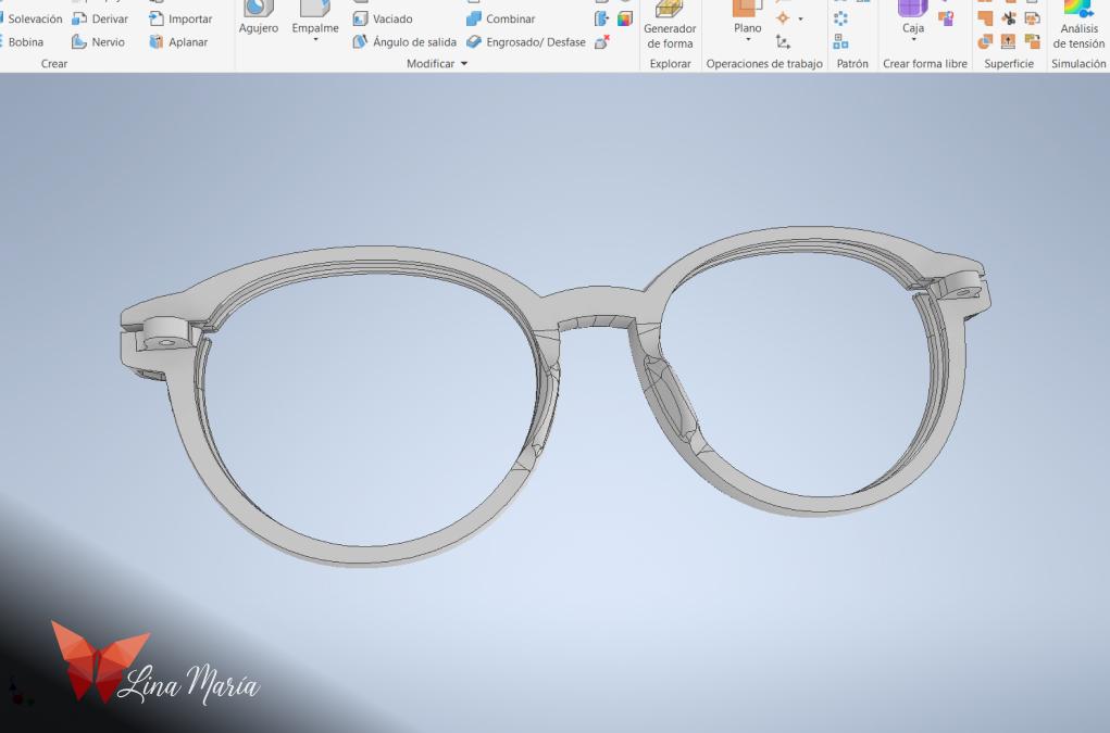
Then, I used the symmetry or mirror function to ensure the other half was exactly the same.
These were the first glasses I printed, which I call Version1. This version worked well with some filaments, but the hinge part, where the arms attach, broke easily with others. I analyzed the design and realized it was due to the direction of the print layers. So, I decided to create the hinge part separately, orienting the print layers for greater strength, and then attach it to the lens frame. This improvement is what I call Version2, which we will see next.
3D Modeling Details for Version 2
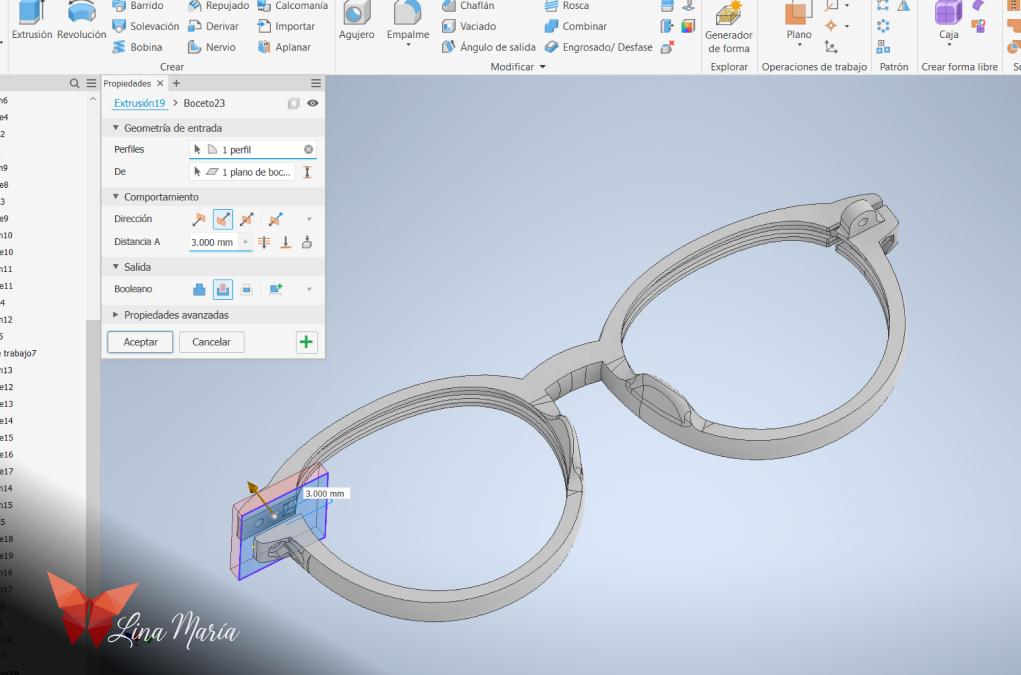
I made a hollow extrusion of the part where the hinges go.
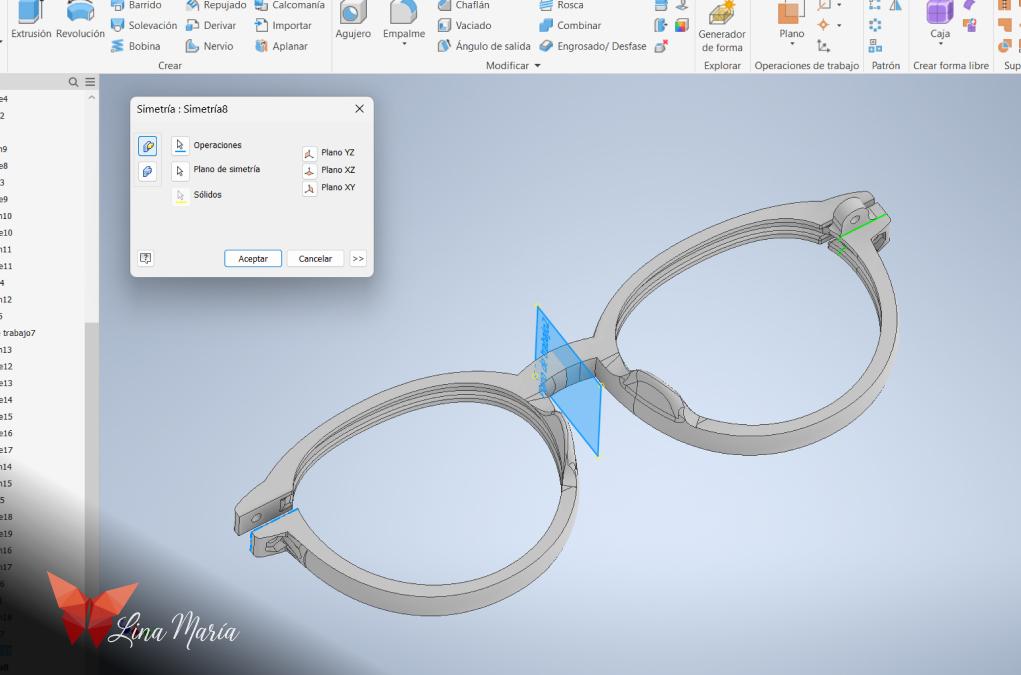
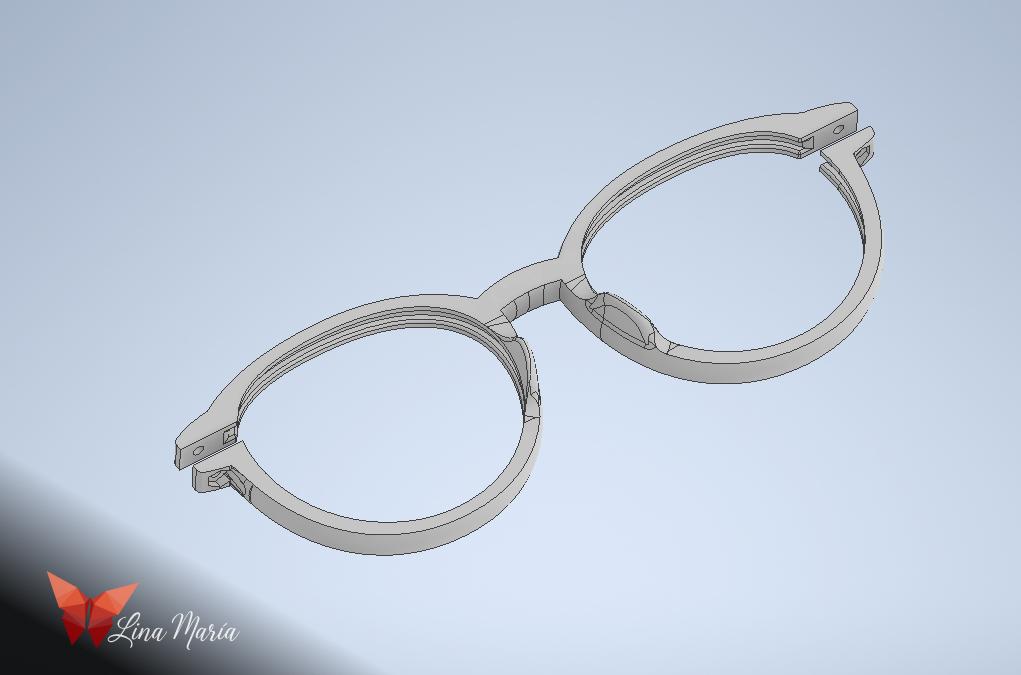
I repeated this with the symmetry or mirror function to ensure it was the same on both sides.
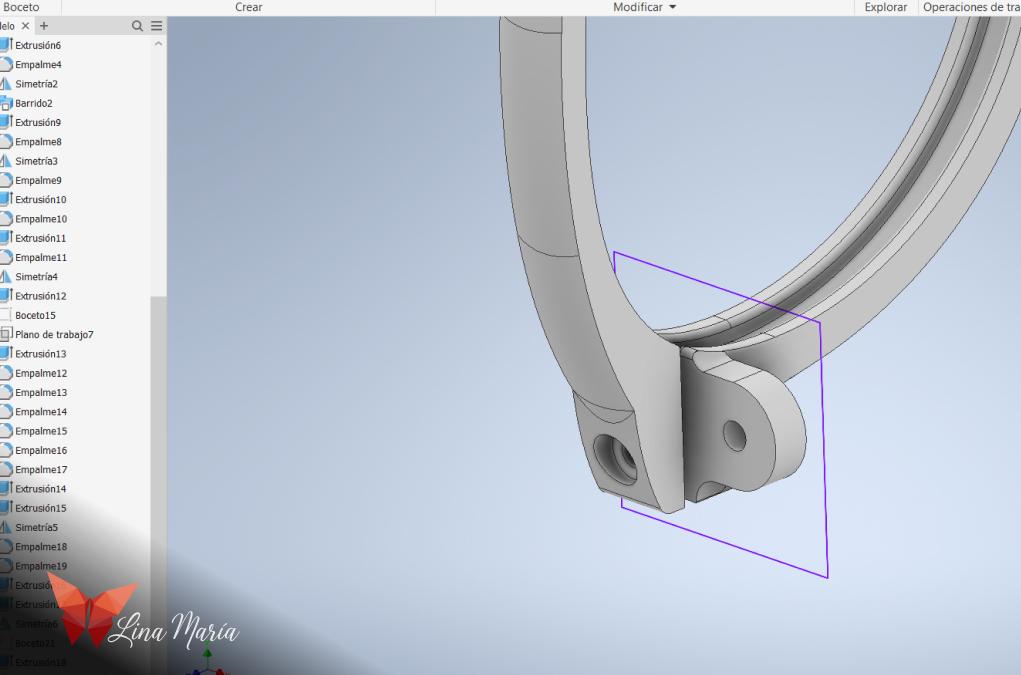
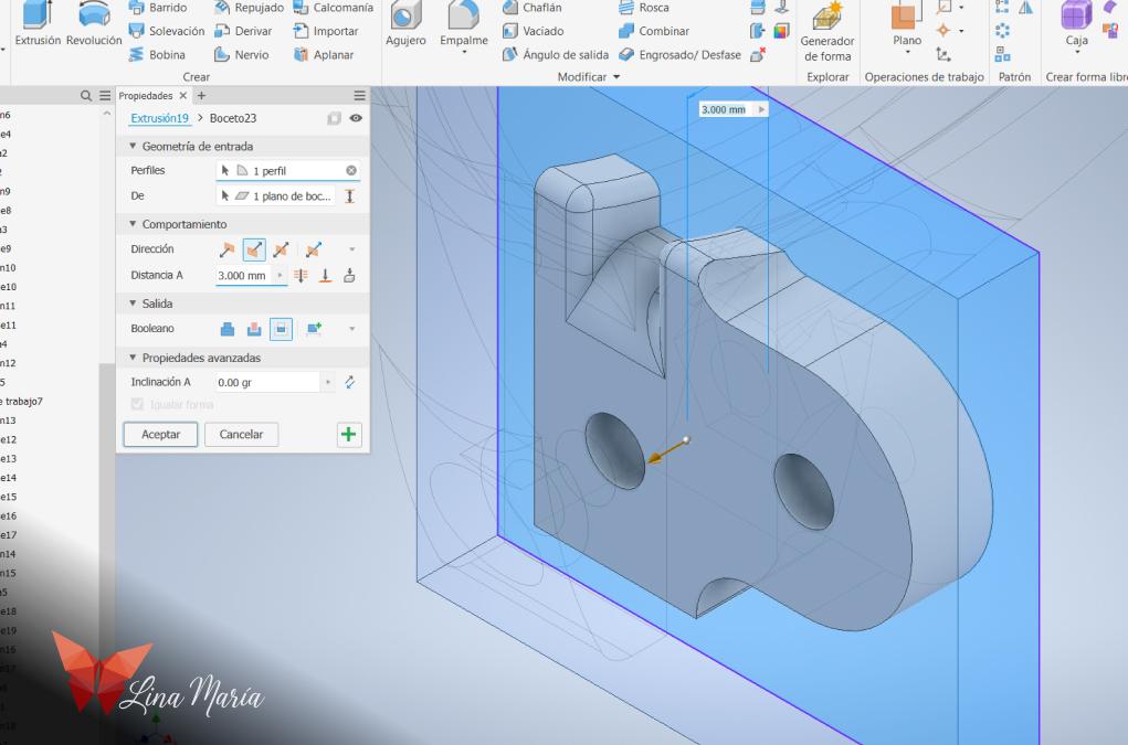
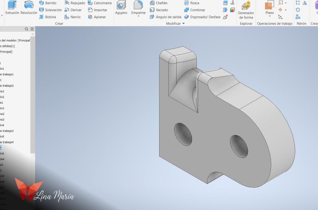
Then, I saved a copy of the file and reopened the extrusion section. Instead of selecting it to be hollow, I chose the intersection option. I saved the file with the name "Hinges."
3D Modeling of the Legs
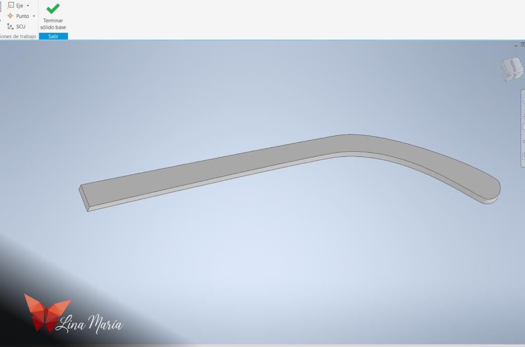
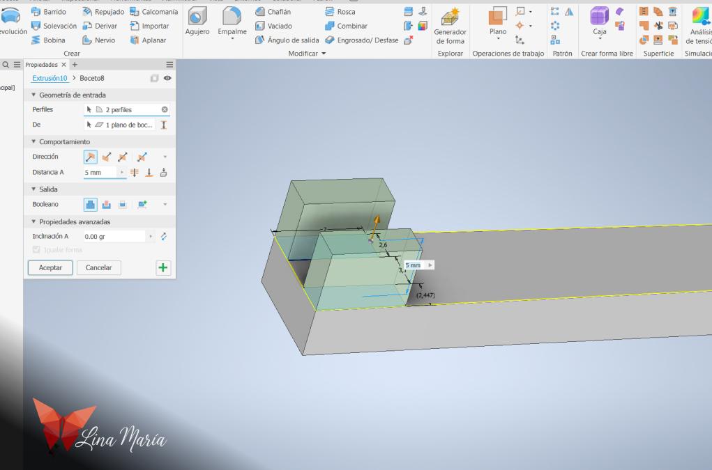
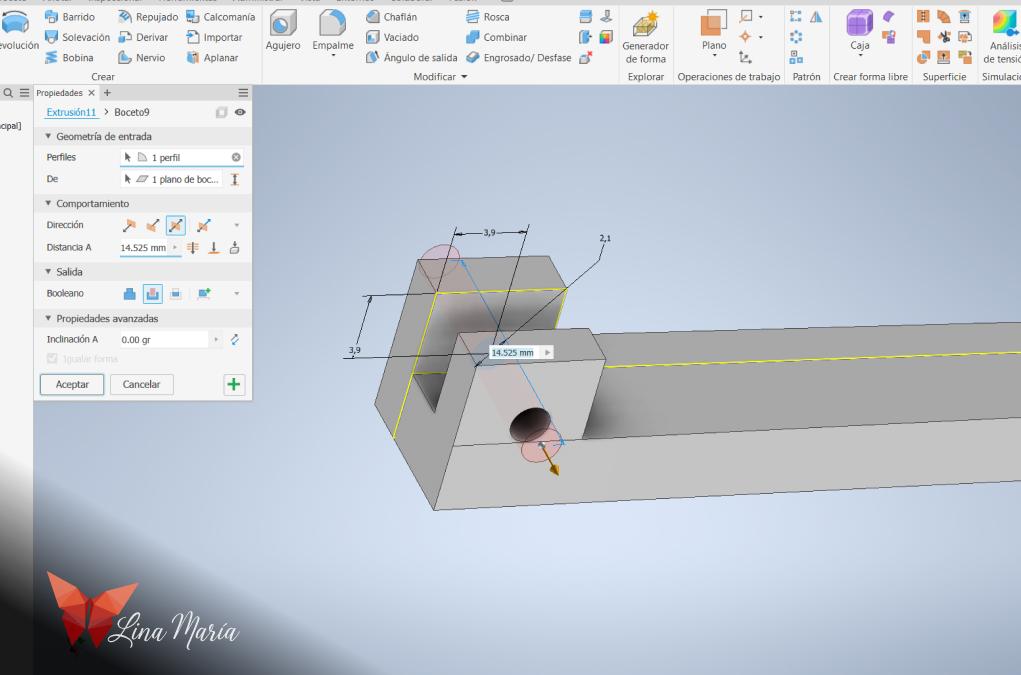
For the arms, I followed a similar process as with the frame. I used the traced version in Illustrator, imported it into Rhino, and performed a small extrusion. I saved the file as "iges" and opened it in Inventor, where I finalized the desired size. I added two squares, which I extruded to create the hinge part that attaches to the frame and holds the arms.
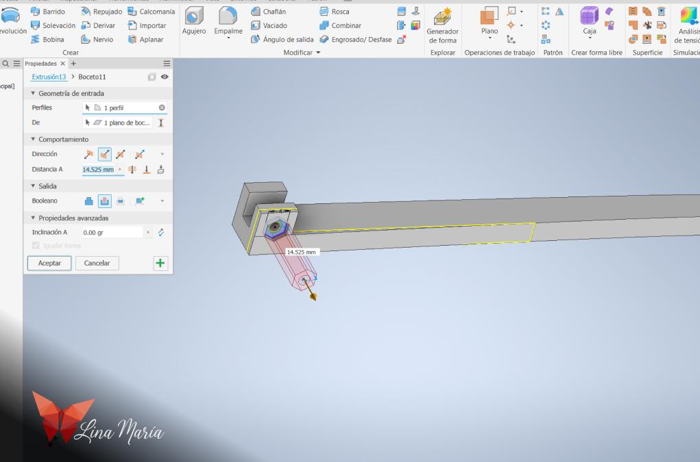
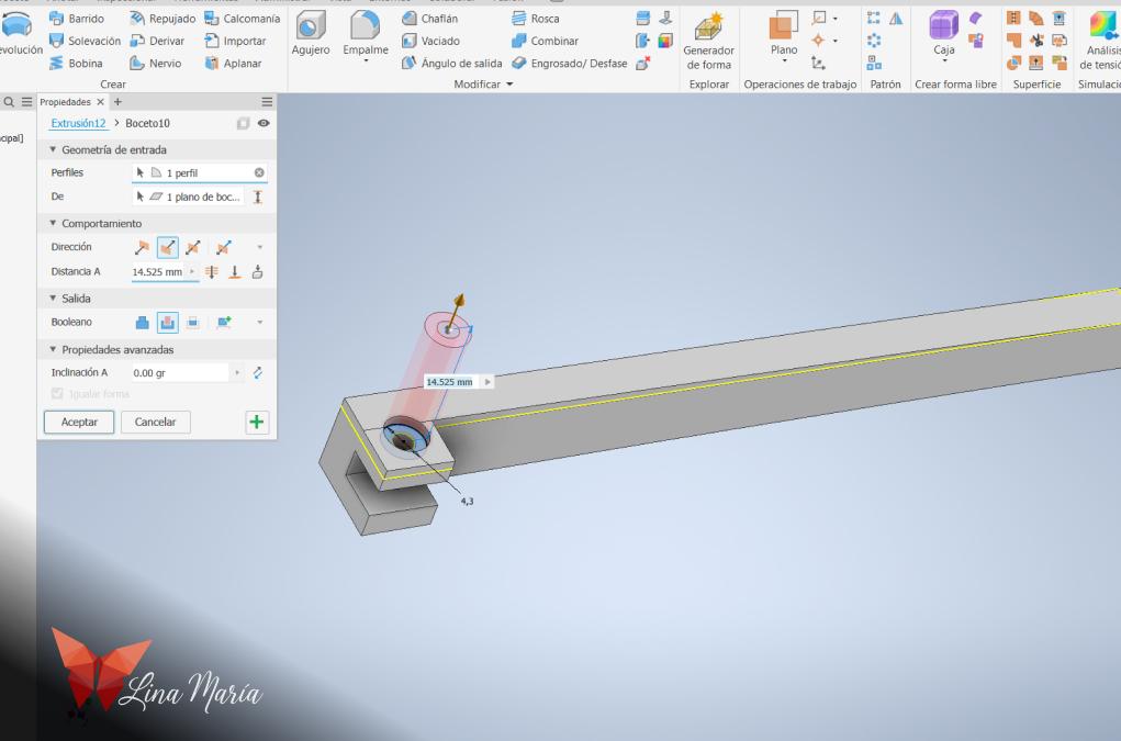
I added the necessary holes and details for the spaces for the screws and nuts.
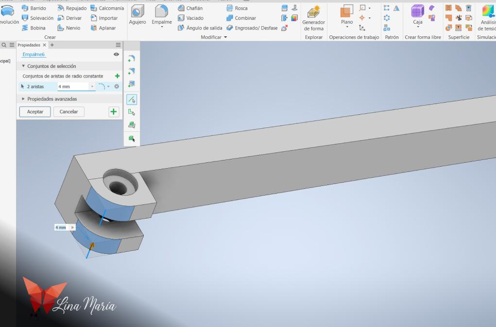
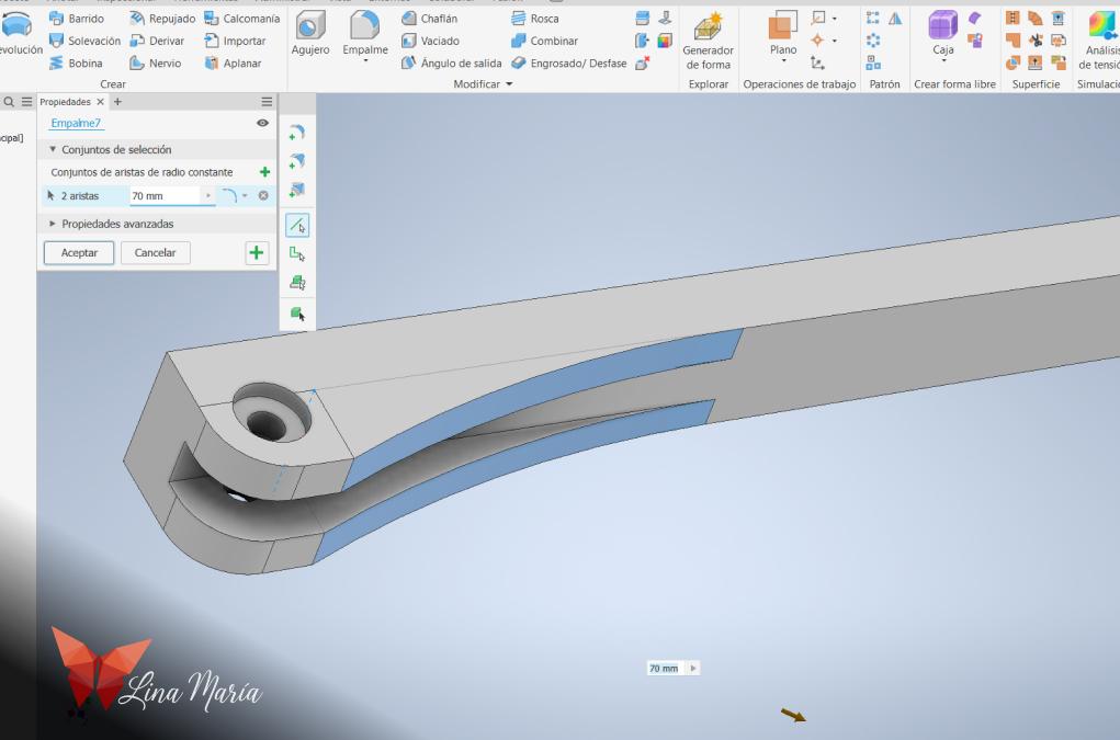
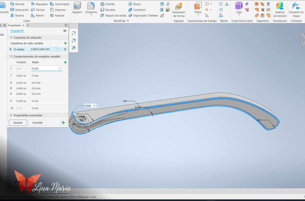
I added several curves to smooth out the shapes.
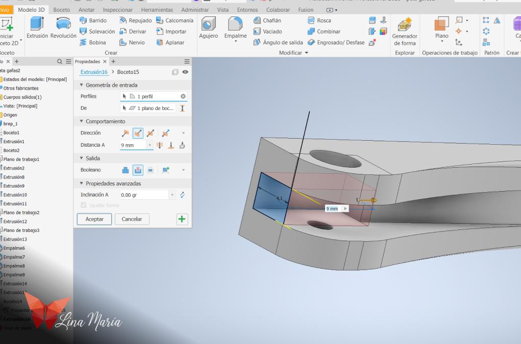
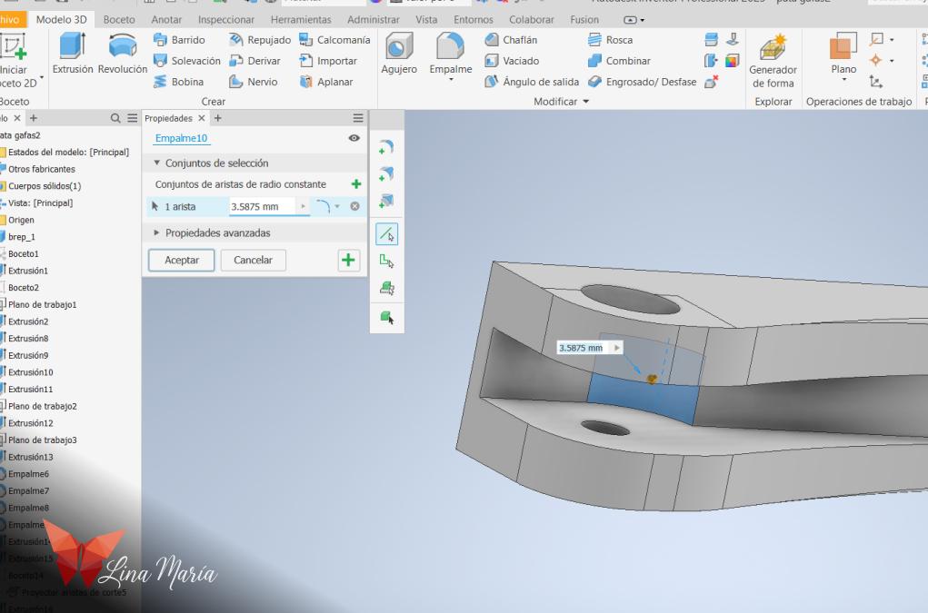
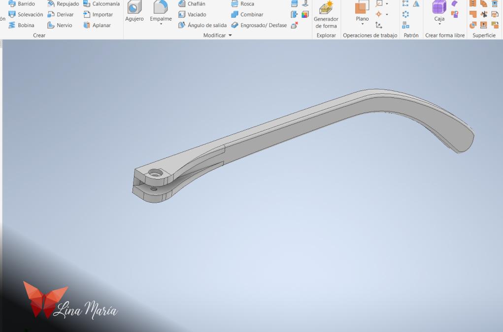
Finally, I ensured there was enough space inside to allow the hinge to rotate within the frame.
About the STL Files
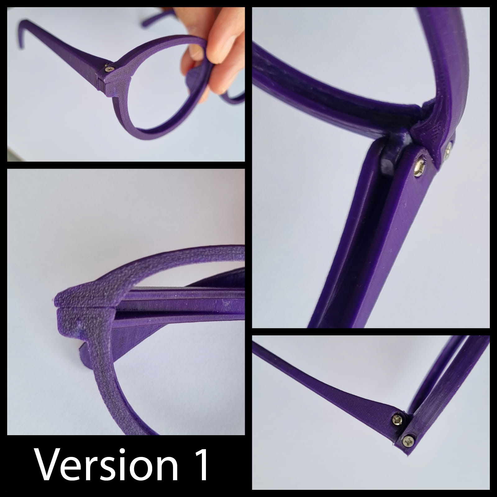
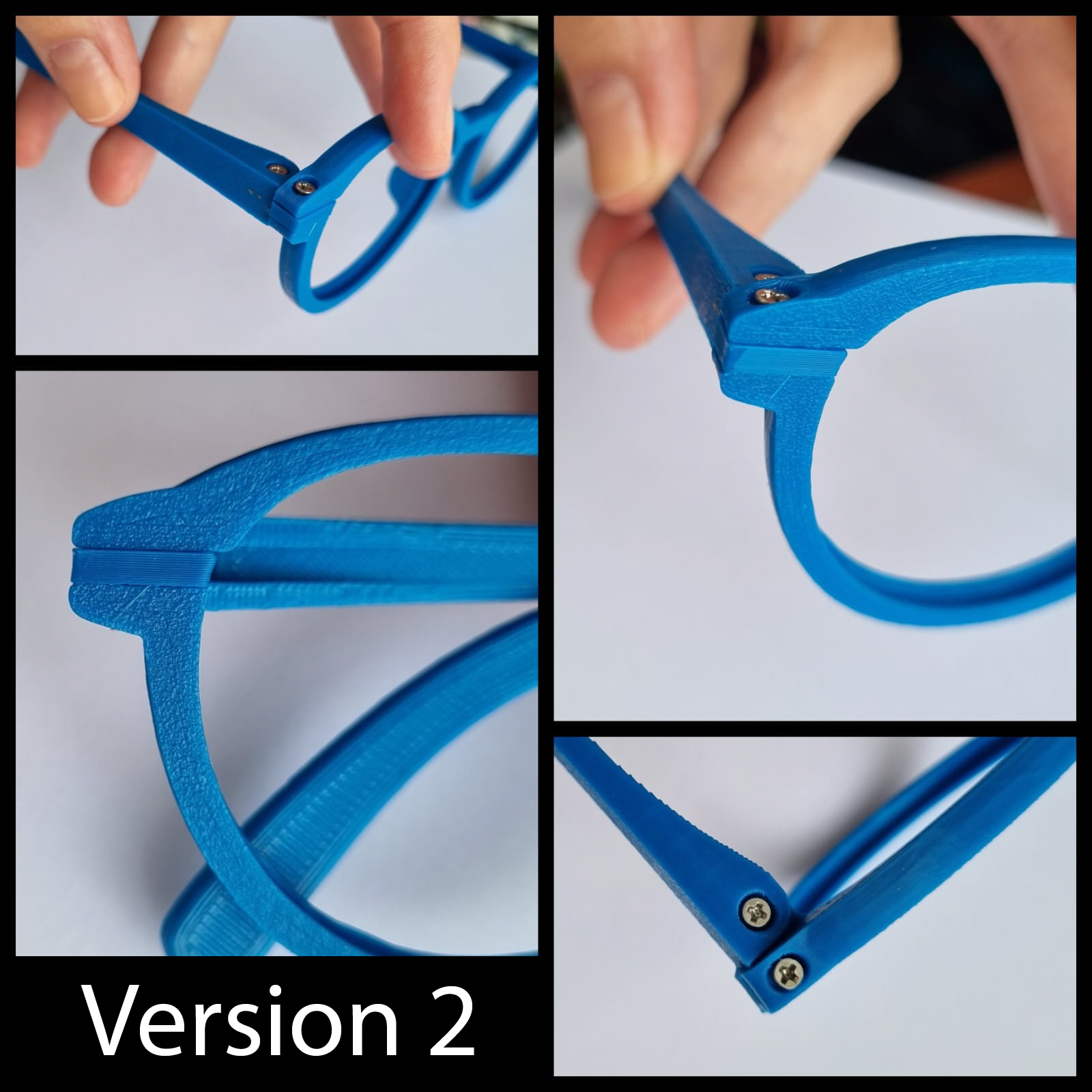
You can find the STL files here: https://cults3d.com/es/modelo-3d/moda/imprime-tus-propias-gafas
3D Printing
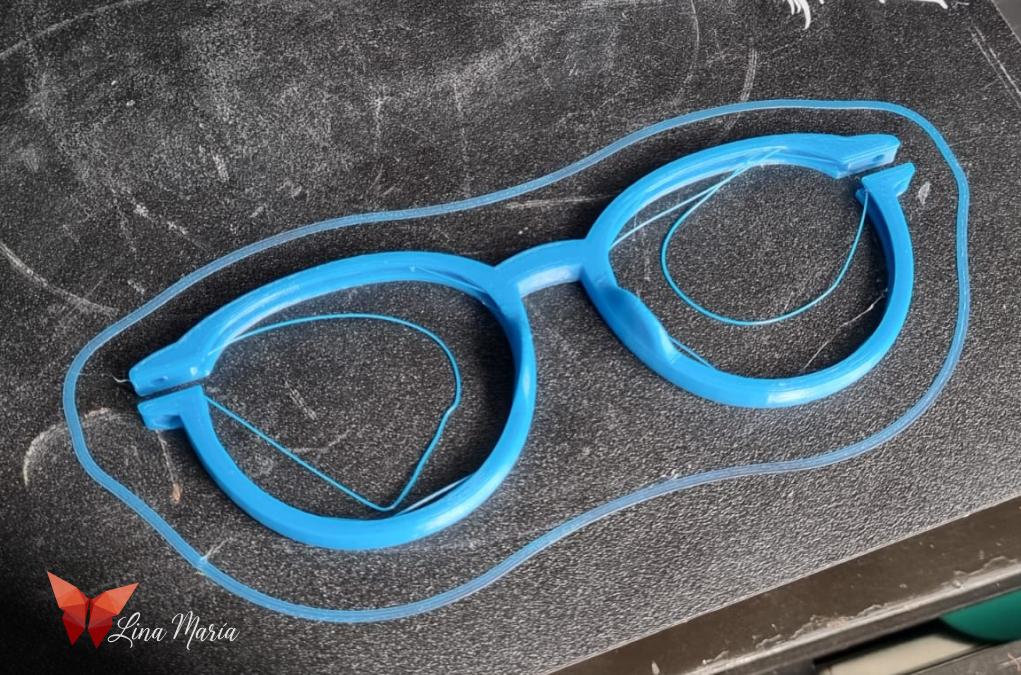
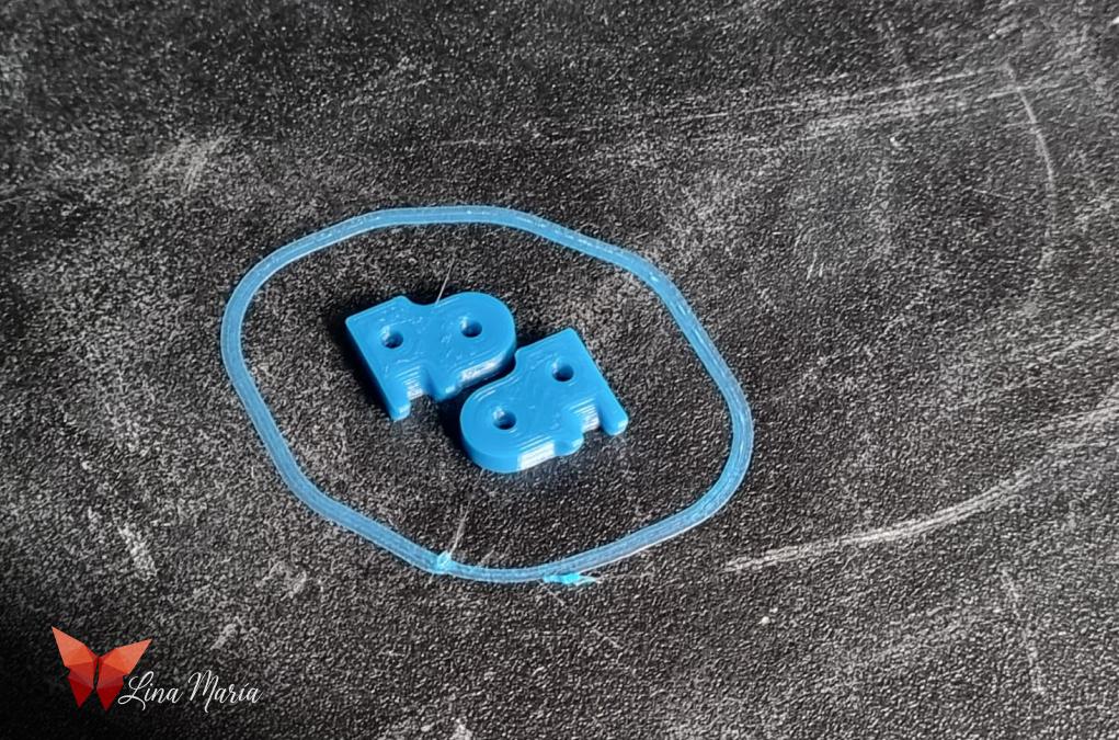
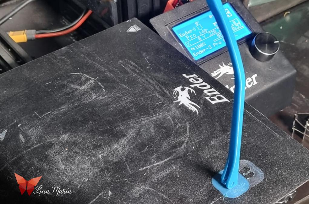
When I printed the files, I didn't use any support material. For the arms, I sometimes printed them vertically, as shown in the image, using the "Build Plate Adhesion" option in Cura set to "Brim" to create additional support around the edges and ensure they stayed attached to the print bed. Other times, I printed them horizontally without any issues.
After printing an arm in one version, I used the "M" (Mirror) option in Cura to create the second arm.
Assembly
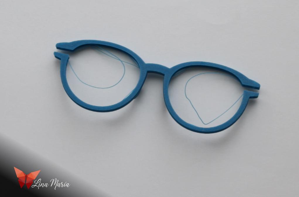
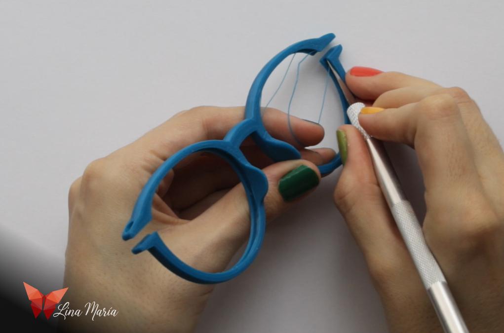
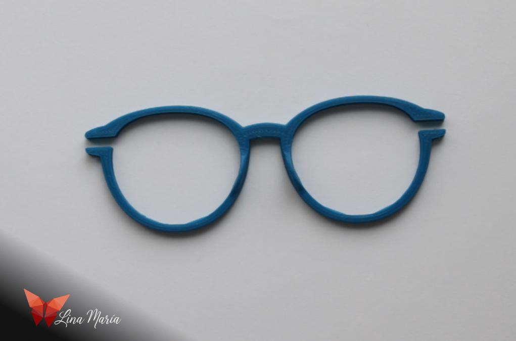
Due to the angle used in the modeling, a few layers of filament were printed in the air while making the frame. However, these do not affect the quality of the glasses, and I simply removed the excess with a utility cutter.
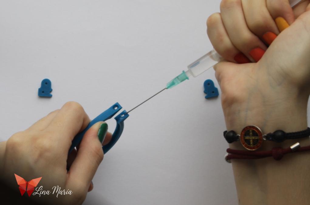
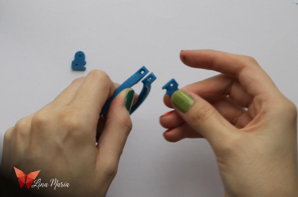
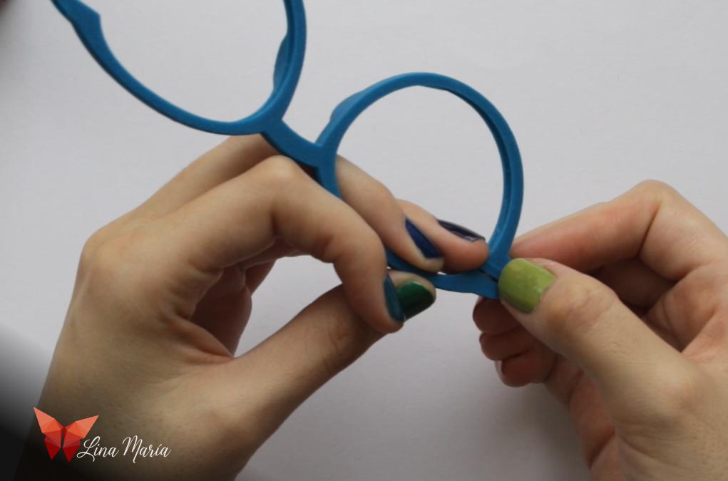
I joined the hinges to the frame with methylene chloride, making sure they were on the correct side. If placed incorrectly, the lenses won't fit properly.
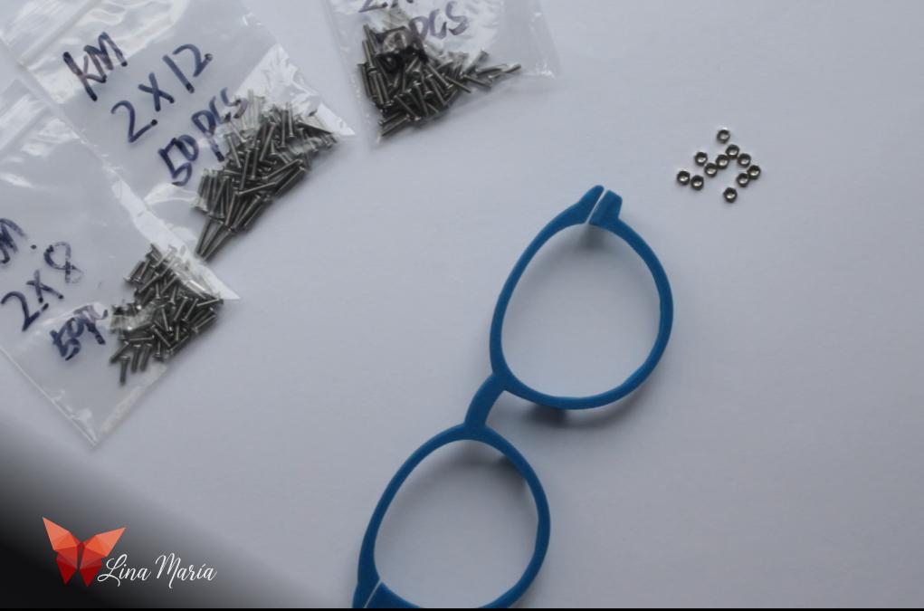
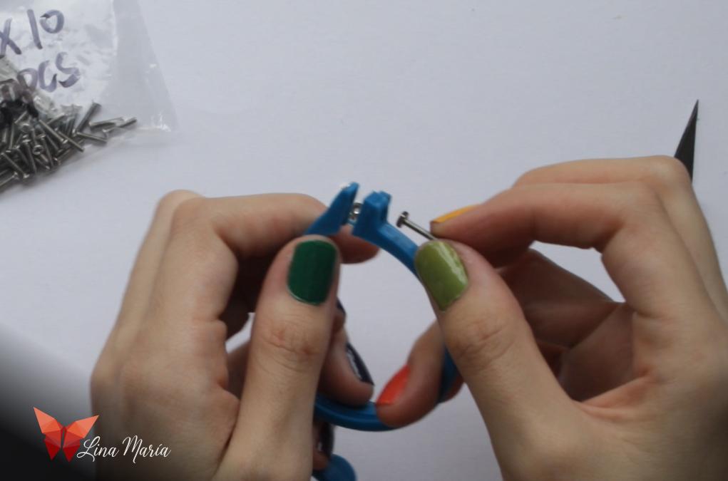
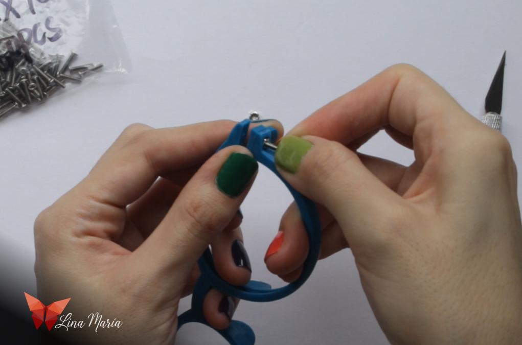
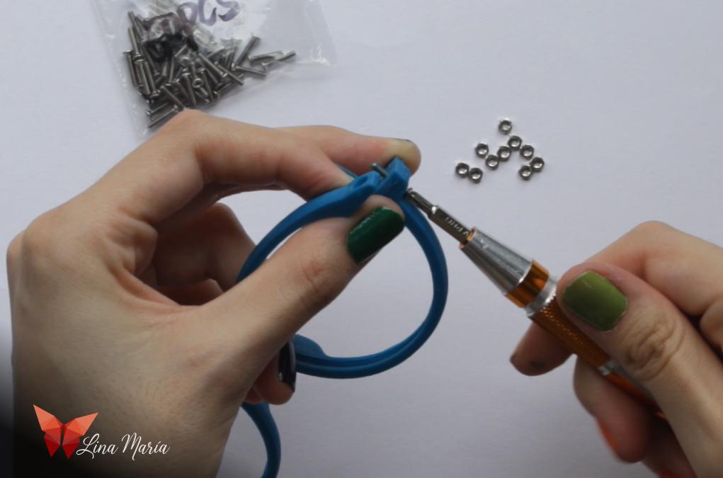
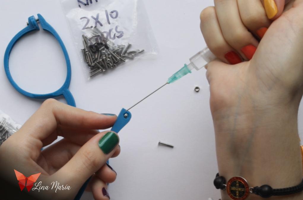
I applied a few drops of methylene chloride with a syringe to the sections where the nuts will be placed. This is to slightly melt the PLA, weld the print layers together, and ensure that when I insert the nut, it remains trapped in place. After waiting 10 to 20 seconds, I put the nuts in place and let the pieces dry for an hour. (It may not be necessary to wait that long, but I prefer to make sure they are completely dry and won't stick to other sections that should remain movable.)
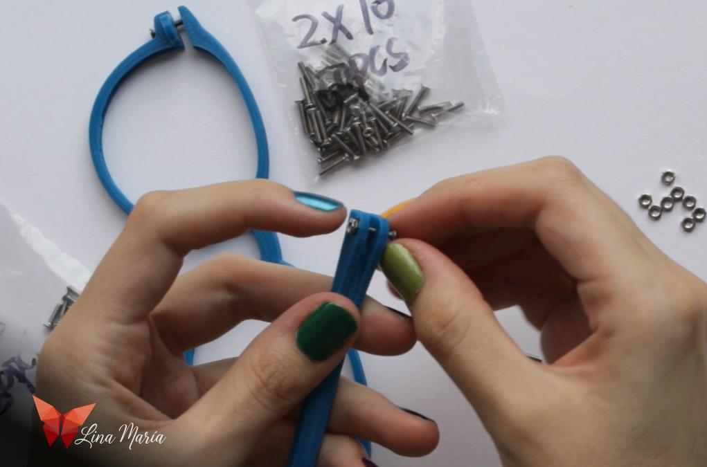
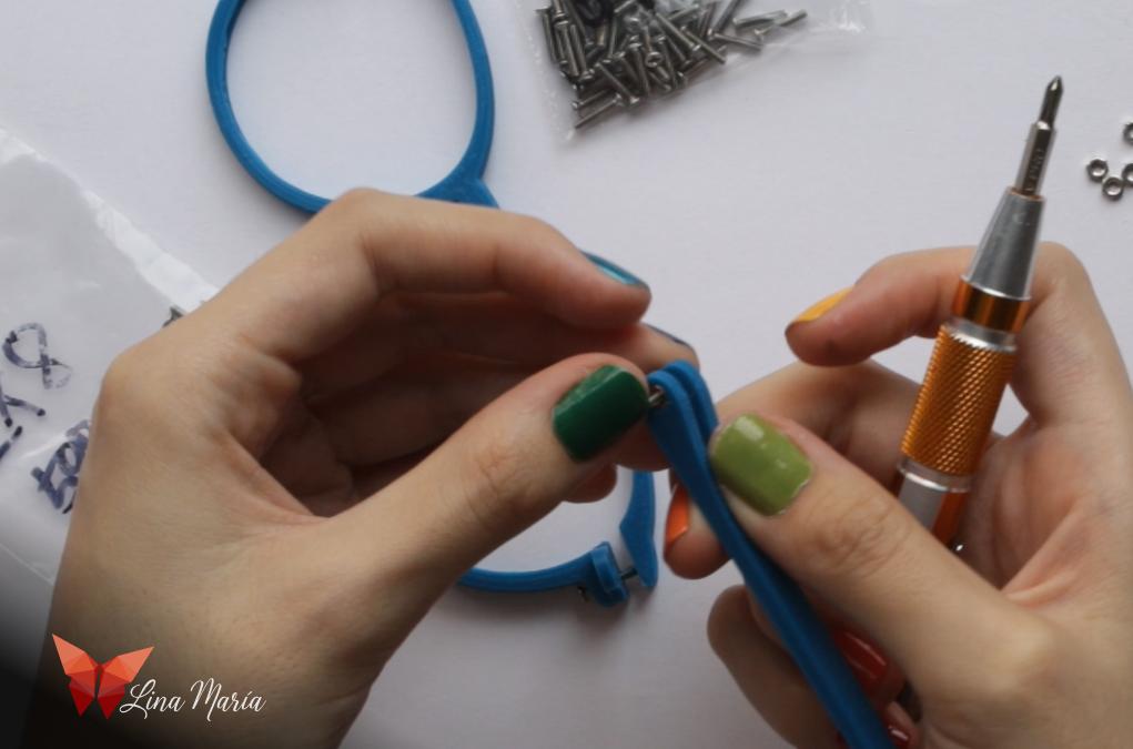
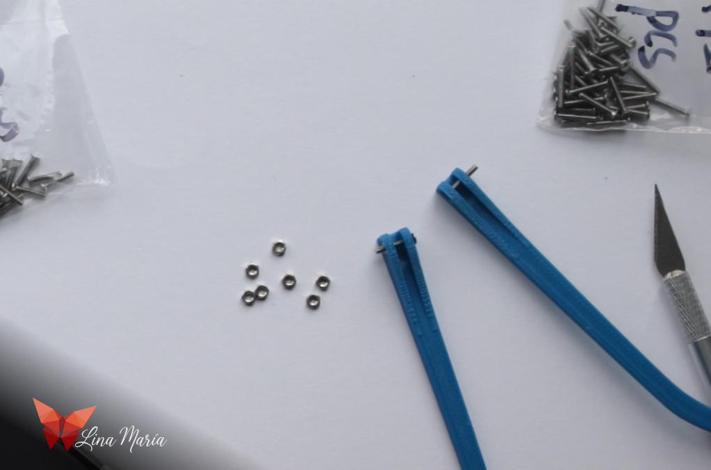
Then, I did the same for the nuts that go in the arms of the glasses.
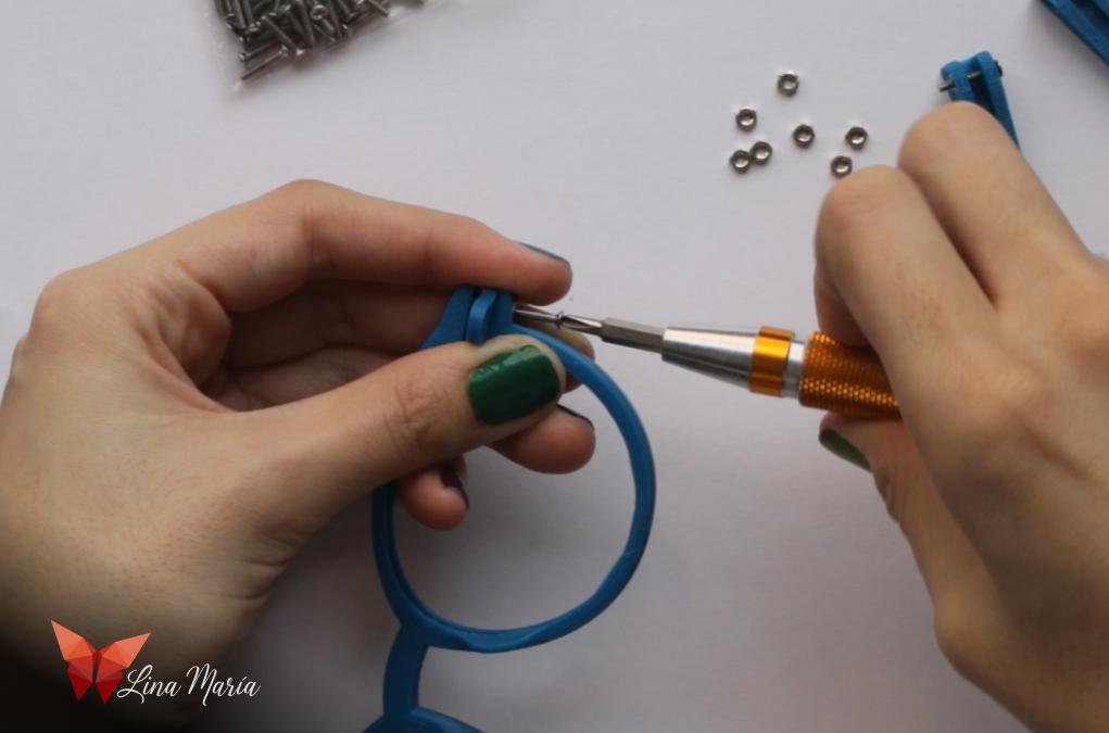
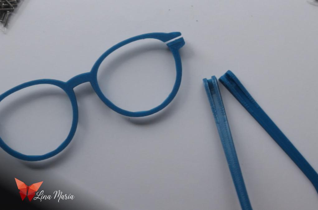
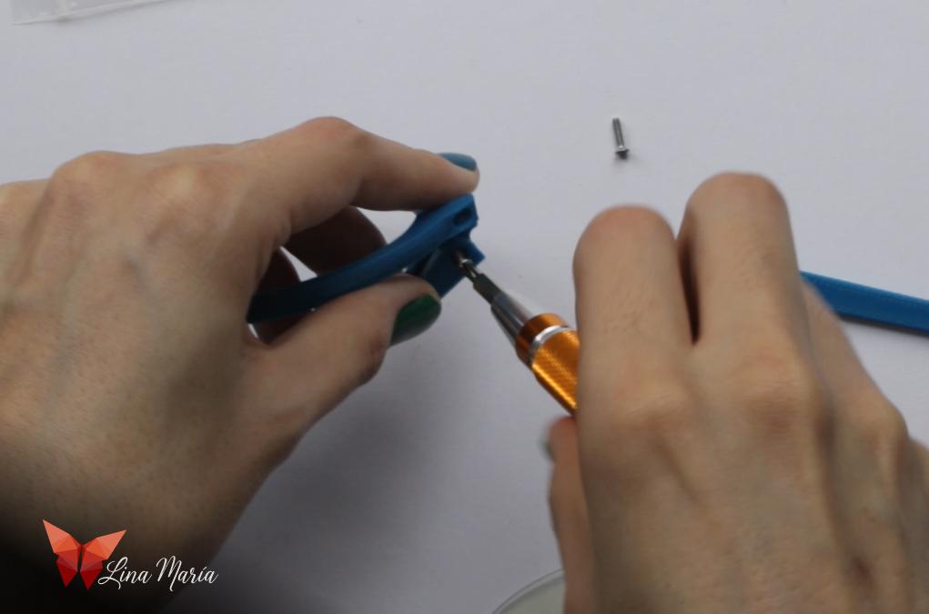
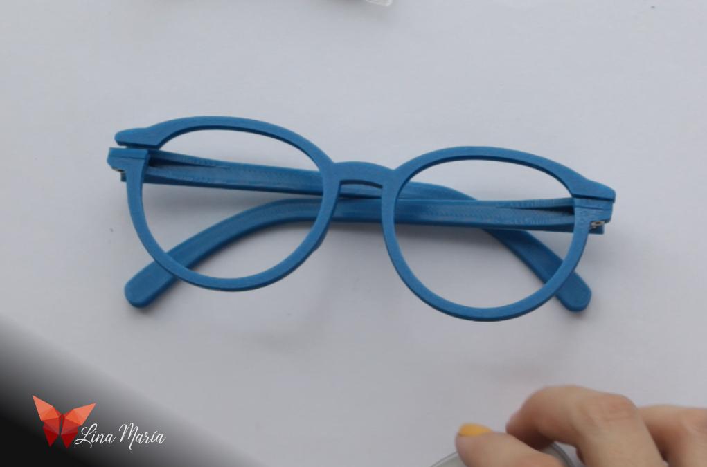
Once they were completely dry, I finally assembled them by inserting the small screws to attach the frame to the arms. The larger screws were used to secure the part of the frame that holds the lenses.
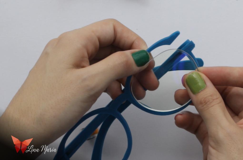
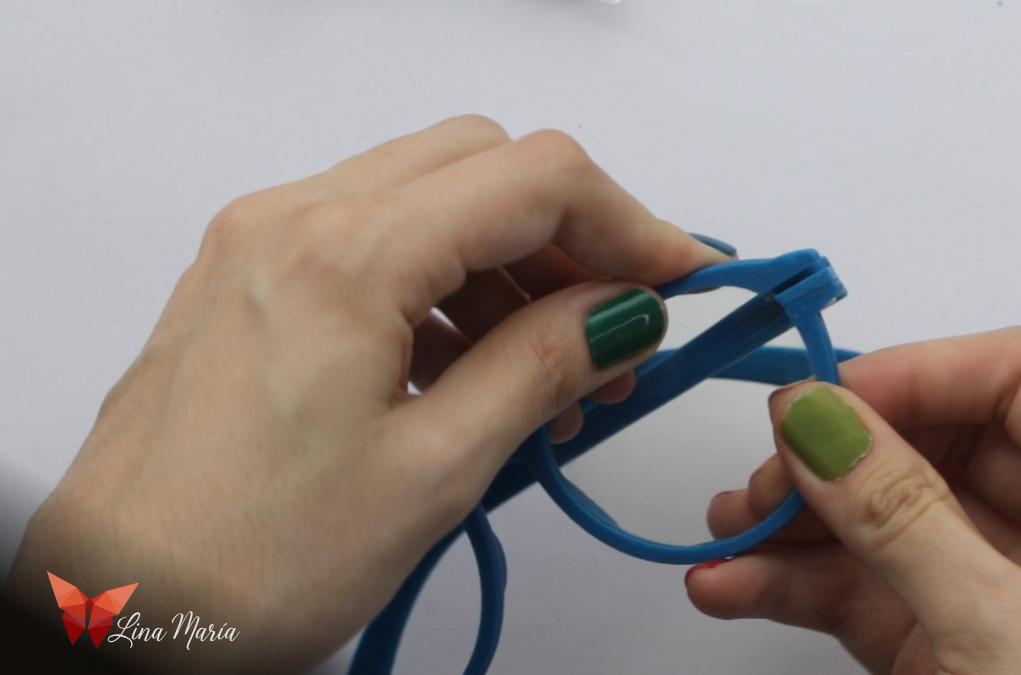
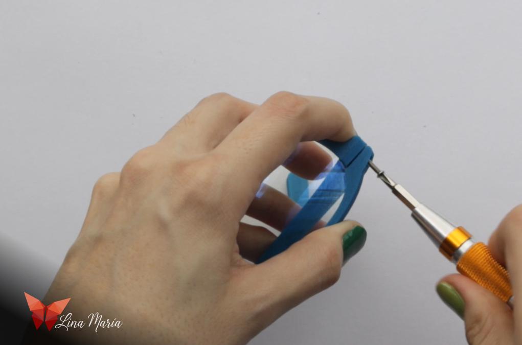
I loosened the screws on the corners of the frame and inserted the lenses, making sure to correctly identify the right and left sides.
Improvements and Customization
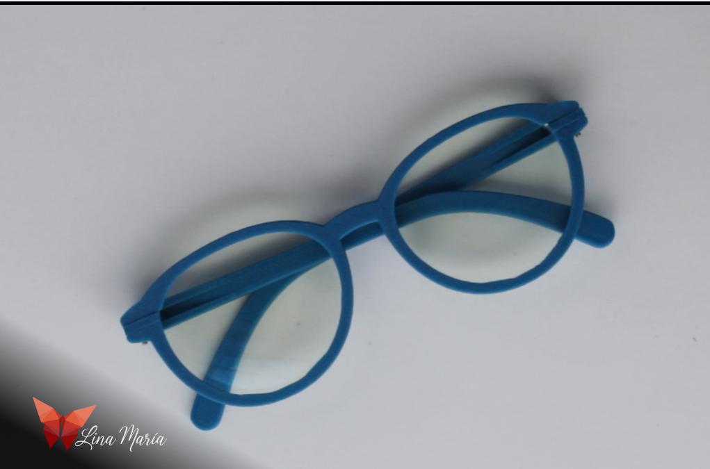
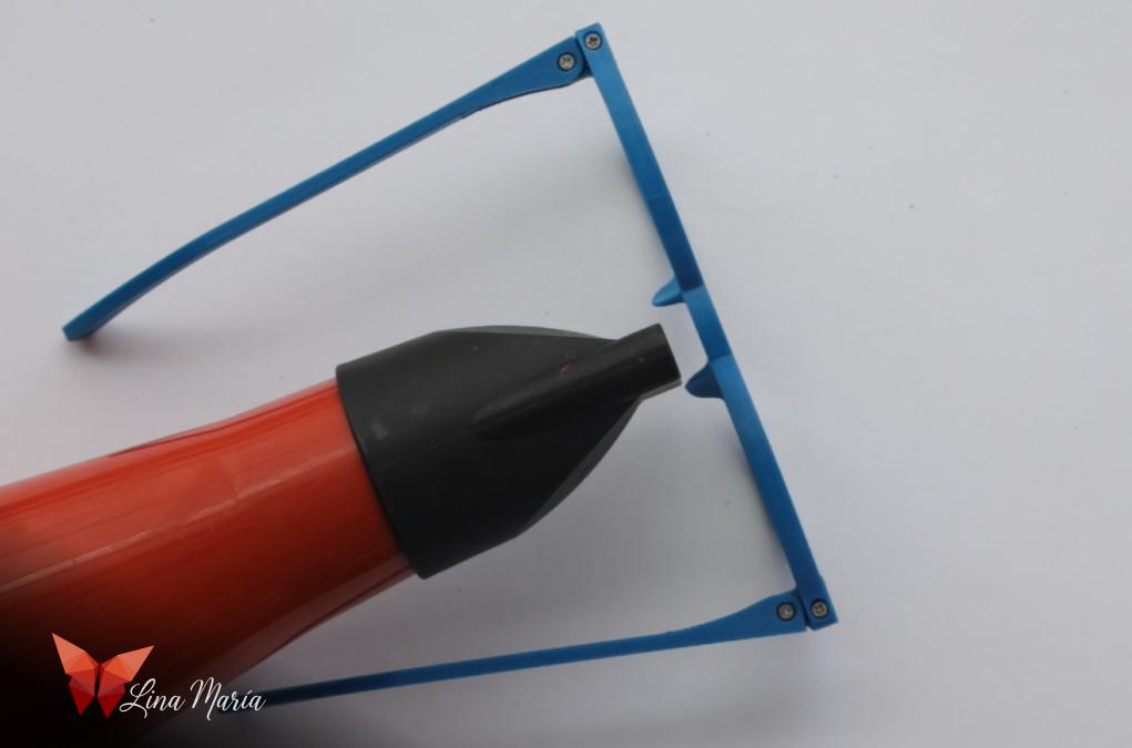
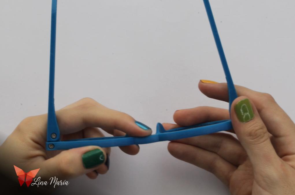
Using a hairdryer on the hot setting and an attachment to direct the airflow, I aimed it at the center for 15 seconds. Then, I gently pressed to give it a slight curve (very gentle, very small).
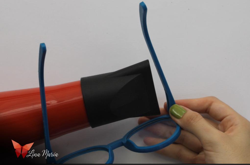
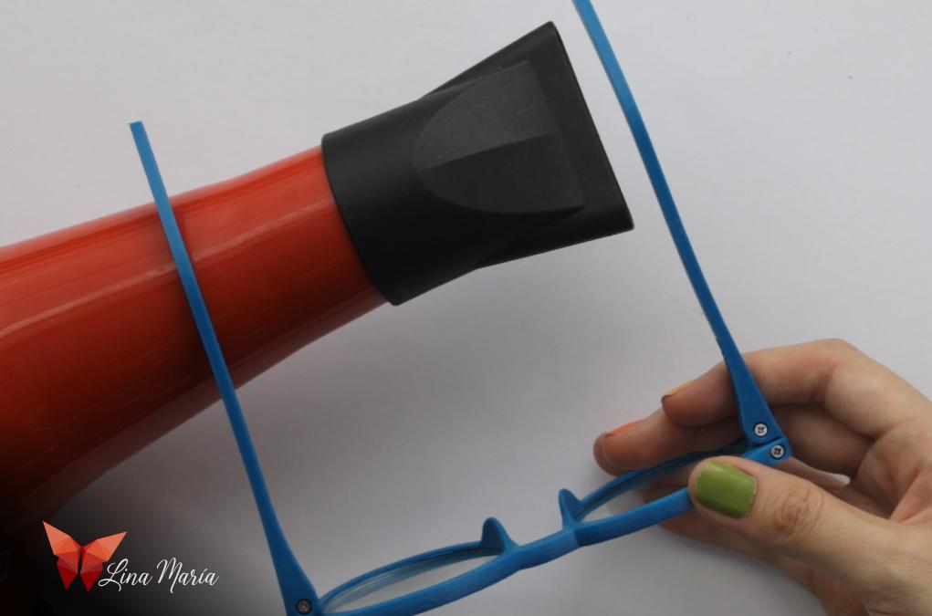
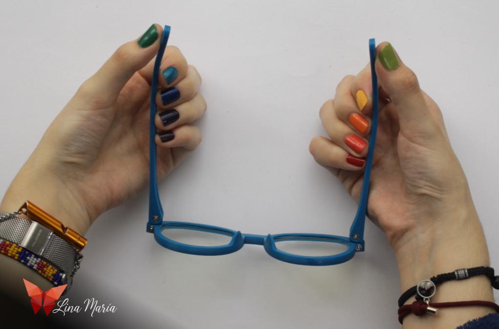
Then, I repeated the same process with the arms, starting near the hinge and slightly bending the arms outward. Next, I made a much more pronounced curve in the part of the arms that go over the ears. I let them cool and kept adjusting until they were perfect for the shape of my head and ears.
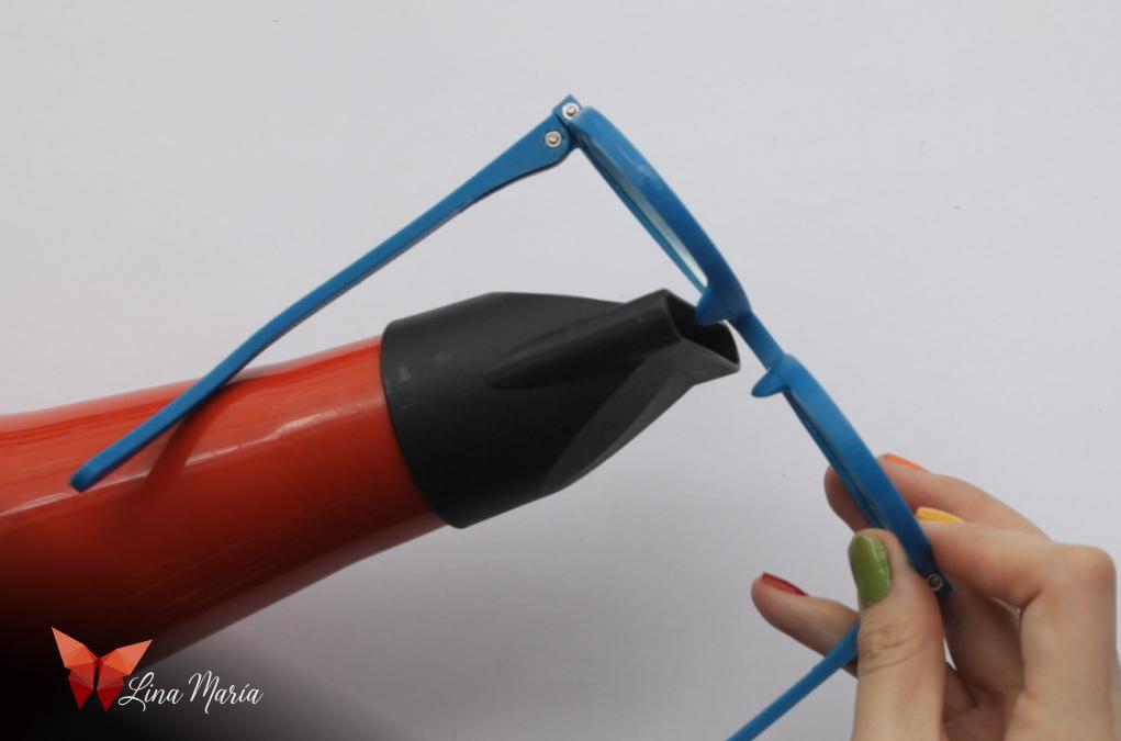
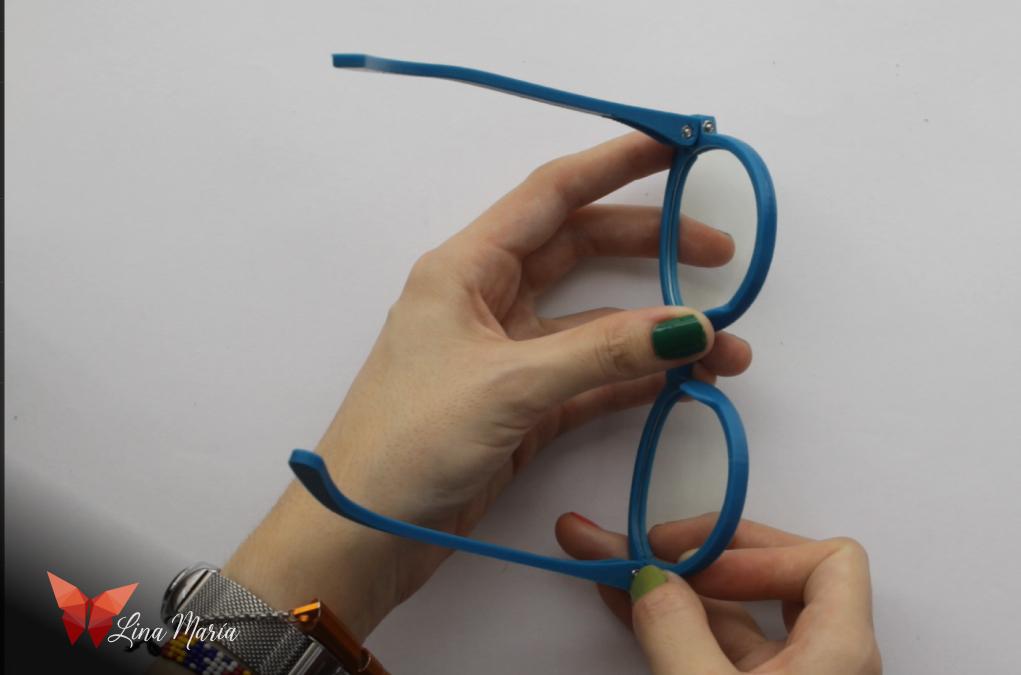
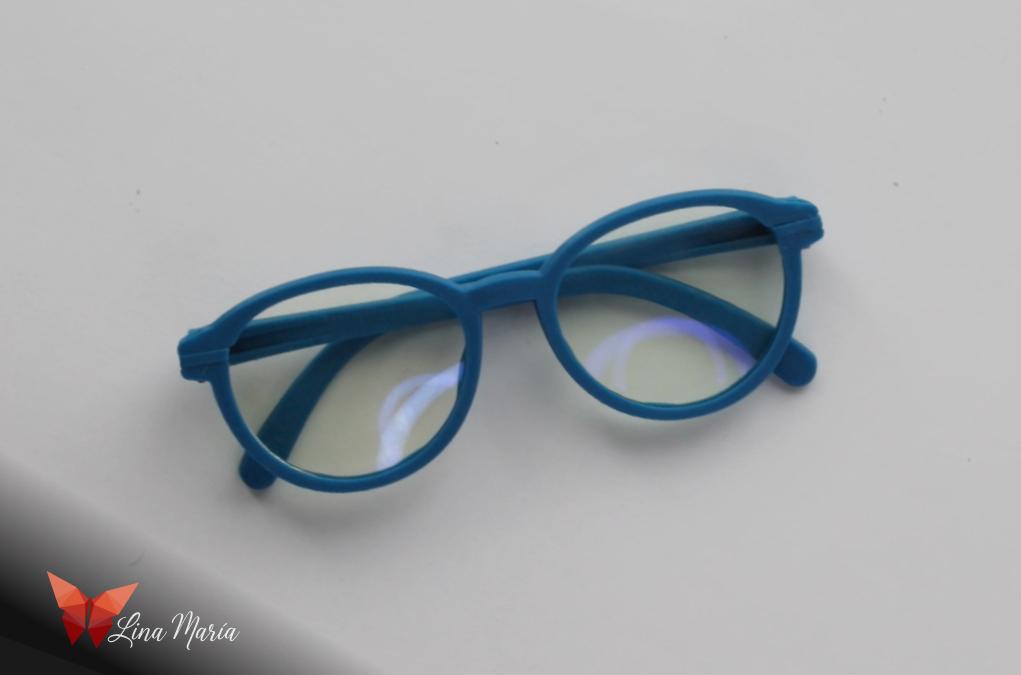
Finally, with the lenses in place, I used the same process of heating and applying pressure to the sections that support the nose. In my opinion, this is the most important part to customize, as it should be adapted to the nose of the person who will wear them, and there are as many different noses as there are people, haha. After adjusting this part on my glasses, I must say that they are the most comfortable glasses I have ever had. I had never had glasses adapted to my nose before, and it’s very pleasant as they don't leave marks.
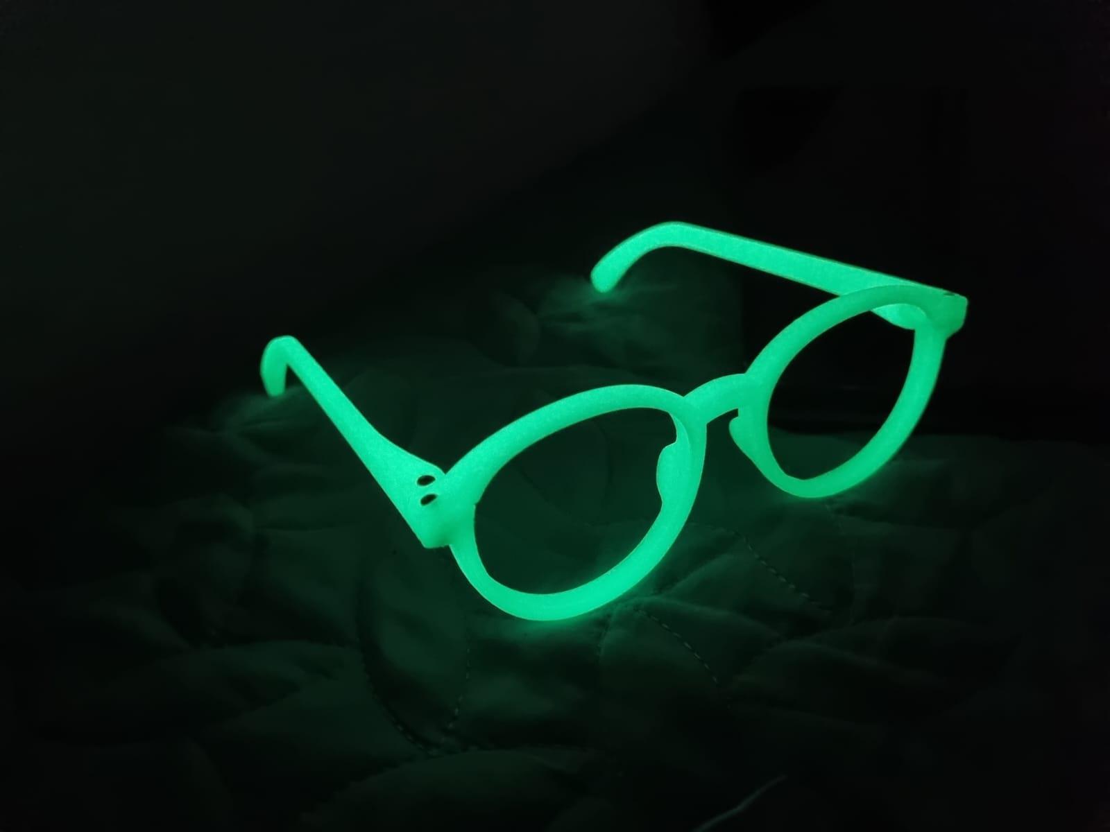
And just for fun, here I show you my 3D printed glasses with glow in the dark filament 😊
The End

And now it's time to print your own glasses and experiment with filaments and colors! 😊